My Fix For Alternator Lt On After Start-up Until High Revs
Discussion


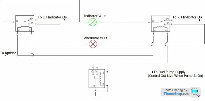
Disconnect the indicator warning light and run 2 leads from that light to 2 x 5 terminal relays as shown, connecting them to terminal 30 of each relay
Extend the leads that have been disconnected from the indicator warning light and connect them to terminal 87a of each relay (Marked on the diagram "To LH Indicator Lts" and "To RH Indicator Lts")
Leaving the Alternator Light original wiring as is, connect a lead to each side of the alternator light and run those leads to the relays, connect them to terminal 87 of each relay as shown
Run a fused ignition supply to terminal 85 of each relay coil
With a short lead, link together terminal 86 of each relay coil and extend that same lead to a 3rd 5 terminal relay connecting it to terminal 87a
Connect terminal 30 of this same 3rd relay to earth (Return/Ground or whatever else you call it)
At this same 3rd relay, connect coil terminal 85 to earth (Return/Ground or whatever else you call it)
At this same 3rd relay, connect coil terminal 86 with a lead to the fuel pump wire that goes directly to the pump (After the pump control relay)
Someone somewhere has got something wrong with this vehicles alternator warning light circuit, the wattage of the bulb should be 3 Watts or more, higher than 3 watts is not a problem apart from heat from that bulb, lower than 3 watts highers the alternators cut-in speed, I don't think a 3watt bulb is made for the type of warning light that is used but I could be wrong
Carrying out the above modification will solve the high cut-in speed problem.
What the circuit does is connect the indicator warning light directly across the alternator warning light to up the wattage to something in the region of 4.4 Watts when in the ignition on position, once the engine starts and the fuel pump has a permanent supply the earth will be broken from the relays and the LH/RH indicator warning light circuit will be back to standard. Remember to allow a second or 2 for the fuel pump to prime before the relays kick in and the crank the engine, the alternator will now have a low cut-in speed
Edited by Penelope Stopit on Friday 12th May 08:08
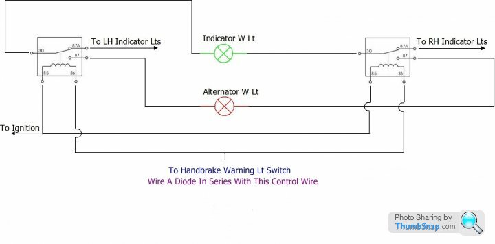
A simplified method of my fix would be to use the handbrake warning light switch to trigger the relay's instead of the fuel pump supply
The problem with this method is that the circuit will only work when starting the car with the handbrake on and the indicator warning light wont work when the handbrake is on
The problem with this method is that the circuit will only work when starting the car with the handbrake on and the indicator warning light wont work when the handbrake is on
Edited by Penelope Stopit on Friday 12th May 08:09
- ***WARNING*****The below method is for a standard 9 diode alternator that includes 3 diodes connected directly to the internal voltage regulator and its warning light terminal*****WARNING*****
- ***WARNING*****Do not place foot on brake pedal when switching off, if needs must, the brake pedal can have foot pressure applied to it when switching off as long as the handbrake is not applied*****WARNING*****
This method works by having the handbrake applied and dabbing the brake pedal when the engine has started

Edited by Penelope Stopit on Friday 12th May 08:10
This fix is very simple to carry out. Leave all vehicle wiring as is, this is an add-on circuit
The warning light shown is the original alternator warning light the same as it is in all my other diagrams
Having started the engine, push the button momentarily
Mount the switch wherever suits

The warning light shown is the original alternator warning light the same as it is in all my other diagrams
Having started the engine, push the button momentarily
Mount the switch wherever suits
Edited by Penelope Stopit on Thursday 19th January 14:57
stevesprint said:
You S owners are as fanatical and meticulous as me with my Griffith, I like your wiring diagrams.
Here's my fix I did a few years ago for the very same annoying LED issue. Its not a straight swap but certainly worth the effort, it does the job and been 100% reliable with no cooling issue as the fan is inside the housing.
Sorry its not an S but proves its possible.
You did a good job, it looks the partHere's my fix I did a few years ago for the very same annoying LED issue. Its not a straight swap but certainly worth the effort, it does the job and been 100% reliable with no cooling issue as the fan is inside the housing.
Sorry its not an S but proves its possible.
This fix is likely to be the most popular and has been around for a long time, unfortunately there are many misleading articles regarding this modification
We know that the 2 or 2.2 Watt bulb being used for the alternator warning light is of too low a wattage for the alternator to have a low cut-in speed
We know that we can hide a bulb behind the dash and connect it in parallel with the original alternator warning light but we also know that this is a bodge job
There are some approximate figures used in the below calculations so as to keep the decimal places down (I have rounded up or down by a small ammount when needed)
A 12 Volt 3 Watt bulb will have a current draw of 0.25 Amps and that will be drawn through the alternators rotor for initial excitation
A 12 volt 2 watt bulb will have a current draw of 0.166 Amps and that will be drawn through the alternators rotor for initial excitation
Unless the alternator is fitted with a very small pulley or is gear driven to up its RPM to Crankshaft RPM Ratio, a 2 Watt bulb drawing 0.166 Amps is too small/low for the alternator to excite and cut-in at low engine RPM
By wiring a 100 Watt resistor in parallel with the 2 watt bulb the current draw through the alternators rotor will be increased to something in the region of 0.29 Amps and provide a lower cut-in speed than a 3 watt bulb does without adding any noticeable load to the starter motor during cranking
Articles knocking around the internet don't tend to mention that the resistor should be fitted in the engine bay or, if fitted inside the vehicle a purpose built heatsink should be used and mounted away from any materials that could have a problem with the heat transmitted.
The majority of people would very likely comment that it doesn't matter where the resistor is fitted due to it carrying current for only a short period of time before the alternator has cut-in and the alternator diode trio (Field Diodes) have now taken over the job of supplying the aternator rotors Voltage/Current, this is where everything starts to possibly go wrong. If an alternator should fail when driving yet the battery is still being charged, there is a very good chance that the alternator warning light would be glowing, should the aternator light be glowing, current will be drawn by the bulb and also the added resistor, a vehicle can be driven for many miles with a glowing warning light if charging and the resistor will without doubt get hot, this is why the resistor is best fitted in the engine bay out on its own somewhere using a small mounting bracket. Who would want a hot resistor inside the car? Anyone carrying out this modification should use a 100 Ohm 5 Watt to 10 Watt resistor. Example Link...http://www.maplin.co.uk/p/wirewound-7-watt-100-ohm-resistor-l100r
It is also possible to remove the alternator, fit and wire the resistor inside the alternator on the slip-ring end shield and add an ignition supply terminal.
Here is one other option I have just thought of, the only thing about this method is that I don't like the idea of hidden bulbs, at least using a hidden warning light in this way will give it some support.
Make a couple of double ended terminals like in the picture using lucar terminals, join wires to them before crimping the terminals together and connect up to the original dashboard bulb and another similar warning light/bulb

Make a couple of double ended terminals like in the picture using lucar terminals, join wires to them before crimping the terminals together and connect up to the original dashboard bulb and another similar warning light/bulb
Penelope Stopit said:
Here is one other option I have just thought of, the only thing about this method is that I don't like the idea of hidden bulbs, at least using a hidden warning light in this way will give it some support.
Make a couple of double ended terminals like in the picture using lucar terminals, join wires to them before crimping the terminals together and connect up to the original dashboard bulb and another similar warning light/bulb
Phillpot said: Think someone else "thought of that" two pages agoMake a couple of double ended terminals like in the picture using lucar terminals, join wires to them before crimping the terminals together and connect up to the original dashboard bulb and another similar warning light/bulb
This circuit was released many years ago
I haven't posted a circuit here I have posted an image of a method that as far as I am aware has not been posted to the internet in the past and feel it could be of some help to those that need a simple rough fix
Gassing Station | S Series | Top of Page | What's New | My Stuff