Starter Interlock Relay, Kill 3 birds With 1 Stone
Discussion


The below circuit achieves 3 objectives and is very simple yet so effective
1 - Car can't possibly be cranked when engine is running, this could save a starter pinion or two
2 - Solves any problems caused by volt drops from ignition switch to starter motor solenoid, more reliable crank voltage
3 - Starter will fail to crank if alternator field circuit goes open circuit, this gives the driver a warning of alternator failure
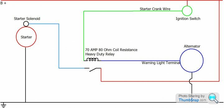

Connect crank wire from ignition switch or start button to relay terminal 86
Connect relay terminal 85 to alternator warning light circuit at instrument cluster or directly to alternator warning light terminal (should be marked D+ or 61)
Connect relay terminal 30 to battery positive
Connect relay terminal 87 to starter solenoid pull-in terminal
1 - Car can't possibly be cranked when engine is running, this could save a starter pinion or two
2 - Solves any problems caused by volt drops from ignition switch to starter motor solenoid, more reliable crank voltage
3 - Starter will fail to crank if alternator field circuit goes open circuit, this gives the driver a warning of alternator failure
Connect crank wire from ignition switch or start button to relay terminal 86
Connect relay terminal 85 to alternator warning light circuit at instrument cluster or directly to alternator warning light terminal (should be marked D+ or 61)
Connect relay terminal 30 to battery positive
Connect relay terminal 87 to starter solenoid pull-in terminal
Edited by Penelope Stopit on Tuesday 4th February 12:52
Alan Whitaker said:
Still in the picture stage at the moment, been busy wiring all the dash gauges and switches, take longer than I thought.
Will be doing the starter / charging next weel
Alan
Only half way done
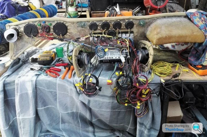
I am drooling at this picture, I love the way you have cable tied the branches and not done anything too tight at the cable exitsWill be doing the starter / charging next weel
Alan
Only half way done
Just look at all those beautiful colours
She's like a rainbow
https://www.youtube.com/watch?v=zphAHMPtu4g
I really should have numbered those relay terminals when drawing the diagram.....silly me
Opening post now edited
As for the alternator wiring
The relay earths through the alternator warning light circuit which is of full negative polarity when the alternator is stationary and positive polarity when the alternator has cut-in and started charging (engine running)
The relay can be earthed at the instrument cluster alternator warning light cable or directly to the alternator warning light terminal which should be numbered 61 or D+
Have wired many of these without problems and saved many a starter pinion from being smashed to bits when a nipper presses the start button with engine running
Maths, it's all about doing the maths to help understand how the alternator circuit works
Quickly and roughly calculated below
Starter cranking speed could be 2500 to 3000 RPM
Starter pinion to flywheel ring gear could be 15/20 to 1
Will go for something like worst scenario
Good starter = 3000 RPM
Highest toothed starter pinion = Ratio of 15 to 1
3000 ÷ 15 = Engine cranking speed of 200 RPM
TVR alternators cut-in speed = approx 1000 RPM
Engine crank pulley say 6"
Alternator pulley 2"
Engine to alternator RPM = Ratio of 1 to 3
Engine cranking speed of 200 RPM = Alternator cranking speed of 600 RPM
Alternator is nowhere near its cut-in speed and starter will crank away
There's more though
12 volt relays will pull-in at something in the region of 7 to 8 volts
12 volt relays will not drop out until something in the region of 3 volts or less, sometimes lower that 2 volts, even if the drop out voltage was 5 volts it wouldn't make this circuit fall over
The thing is battery voltage when cranking will be approx 9.6/10 volts and even if an alternator had a 10 watt warning light to bring it's cut-in RPM down and managed to generate........Lets say 5 volts at 600 RPM......There would still be 5 volts across the relay coil to hold it in
Done the above using best figures to try and break the circuit but can't break it
In practice the figures would very likely be more in the circuits favour
Gassing Station | S Series | Top of Page | What's New | My Stuff