Discussion


Norman don't die of shock, I have finally got round to looking at it!
Here's the test setup
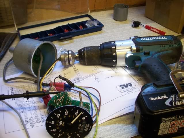
Yes Norman that is the same sender you sent me covered in sh!t!
I gave it a bit of a clean.
Don't panic the cog comes off the end by removing a circlip.
The output from the sender is a nice crisp 12v square wave that varies in frequency accoring to the speed (as you'd expect).
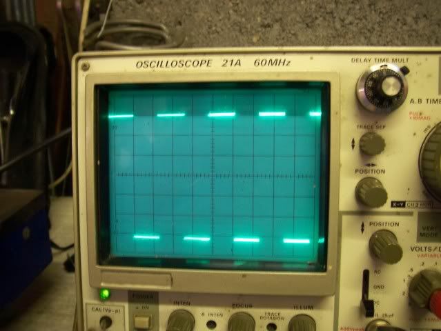
Each cm vertically represents 2 volts, so 6 squares = 12 volts.
You can see the volts/div control to the botton right of the pic if you're interested.
Anyway I have spent a lot of time trying to work out the speedo problem to the point that I have just ordered some electronic components, I hope thats OK Norman.
If I'm right then I'll return a fully working speedo to you free of charge.
I have so far identified one problem with the speedo - there may of course be a second fault once that is resolved.
Watch this space!
Here's the test setup
Yes Norman that is the same sender you sent me covered in sh!t!
I gave it a bit of a clean.
Don't panic the cog comes off the end by removing a circlip.
The output from the sender is a nice crisp 12v square wave that varies in frequency accoring to the speed (as you'd expect).
Each cm vertically represents 2 volts, so 6 squares = 12 volts.
You can see the volts/div control to the botton right of the pic if you're interested.
Anyway I have spent a lot of time trying to work out the speedo problem to the point that I have just ordered some electronic components, I hope thats OK Norman.
If I'm right then I'll return a fully working speedo to you free of charge.
I have so far identified one problem with the speedo - there may of course be a second fault once that is resolved.
Watch this space!
I guess we could be getting confused here - as I have a sender unit and a speedo but no car loom in between - I've wired it as per this
http://www.tvrsseries.com/drawings/tvrswiringdiagr...
N - Black
B - Brown
Y - Yellow
Regardless I have it wired correctly as I have Voltage on the correct pins of the IC's and the speedo signal going through the first amplifier.
http://www.tvrsseries.com/drawings/tvrswiringdiagr...
N - Black
B - Brown
Y - Yellow
Regardless I have it wired correctly as I have Voltage on the correct pins of the IC's and the speedo signal going through the first amplifier.
Gassing Station | S Series | Top of Page | What's New | My Stuff