Rear wheel bearing replacement
Discussion


For those who've never done it, this may go some way to de-frightening the task... and for those who have, feel free to chip in with suggestions and horror stories 
You will need one new wheel bearing and one hub carrier
Tarting-up the carrier isn’t essential but adds to the sense of satisfaction.
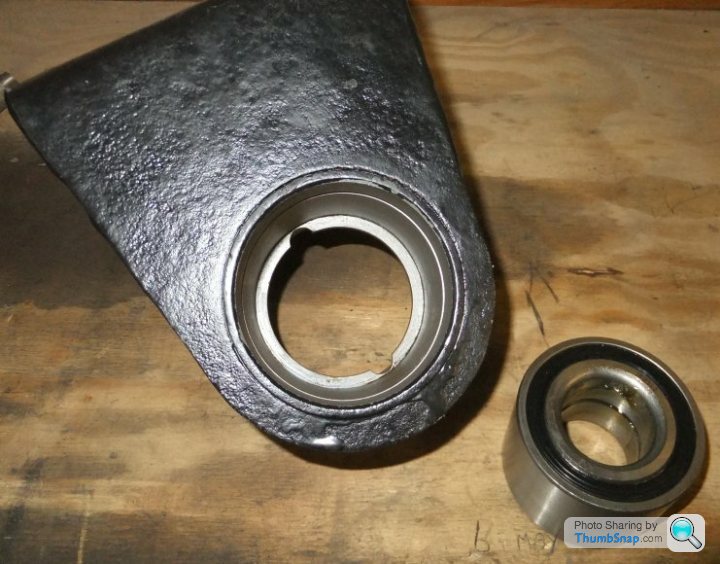
First make sure the bore of the carrier is undamaged (no dents, score marks etc.) and free from rust and that the circlip groove is similarly sound, with no debris stuck in it. The bore should also be free from grease or oil that might allow the bearing to spin in it.

Ensure the outer surface of the bearing is dry and insert it squarely into the bore…
whereupon you should find it will slip easily a good way in. The outer few millimeters of the bore are slightly larger than the bearing which allows it to be square before you try and press it in.
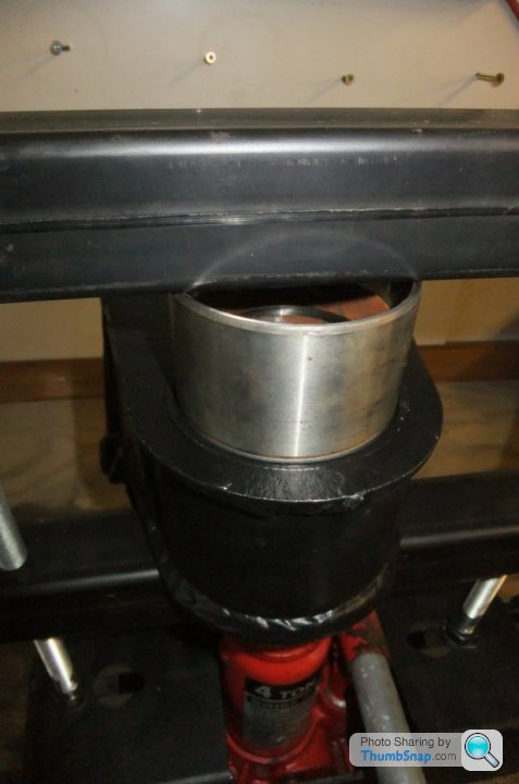
You can use a big bench vice to drive the bearing in, but I’d modified my simple bench press with a couple of lengths of box section (I originally built it as a bike spring compressor):

and it was a simple matter to position the hub carrier and bearing within it:

Jacking-up the carrier pushes the bearing into the bore…
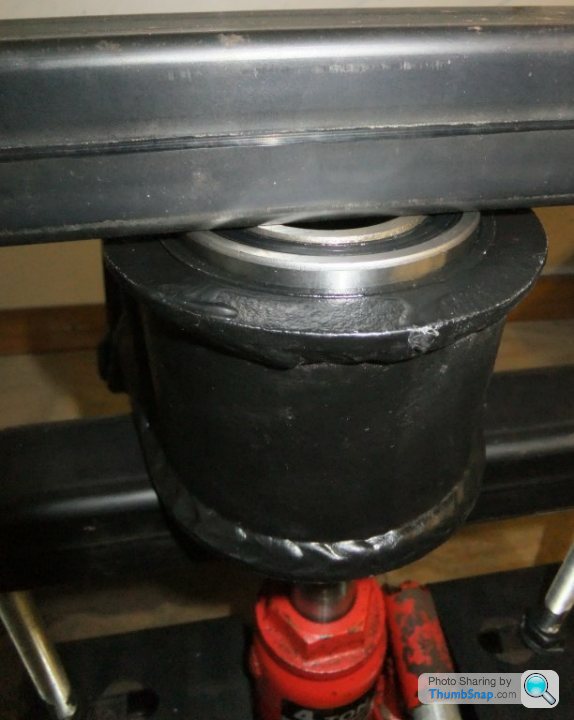
…until the carrier ‘bottoms’ on the top box-section.
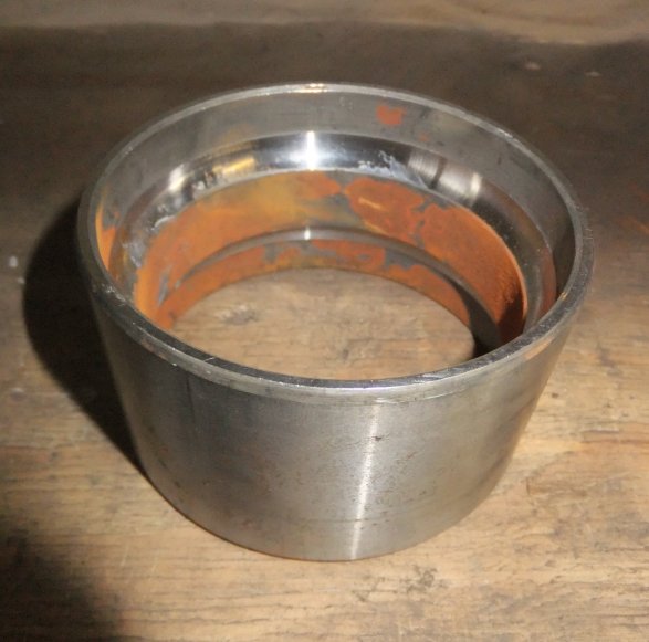
What you then need is a packing piece or spacer to get the bearing the rest of the way in; the ideal instrument is another bearing of the same diameter – or at least the outer race from an old one (I kept this one for such jobs):
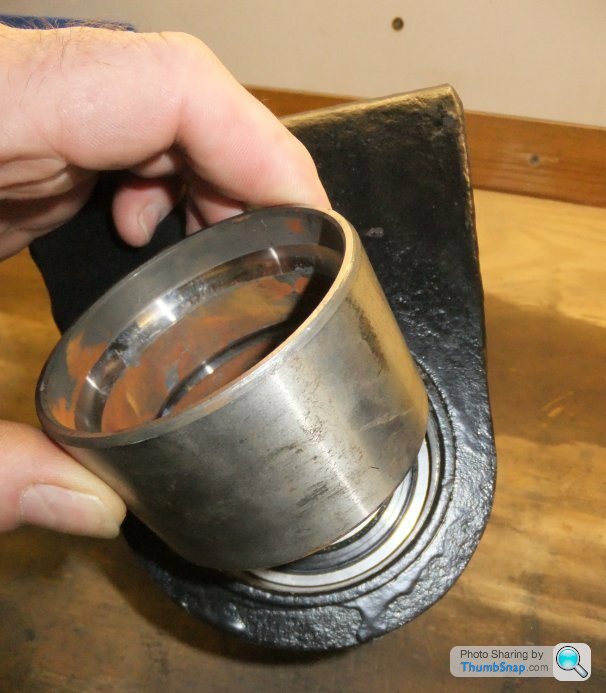
Position the spacer/ bearing shell exactly on the outer rim of the new bearing and apply more force…
until the bearing is firmly against the locating ridge inside the carrier bore.

The old bearing shell lifts straight out…
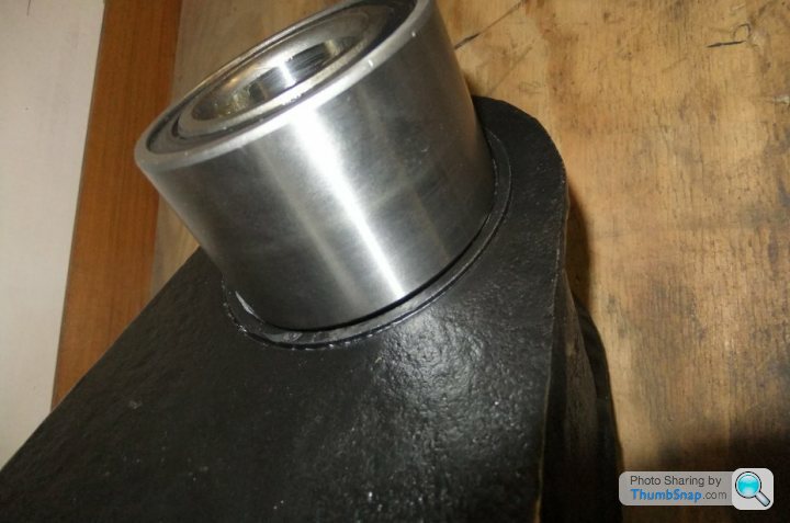
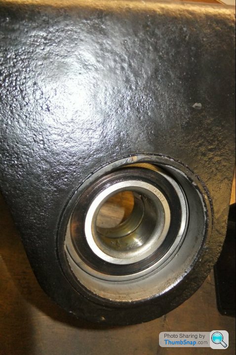
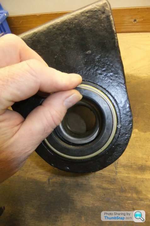
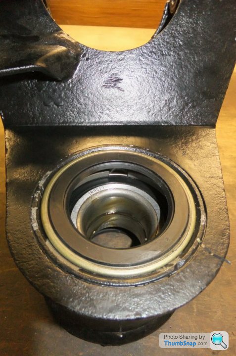
and the bearing will be seen to be sat flush with the inner edge of the circlip groove:
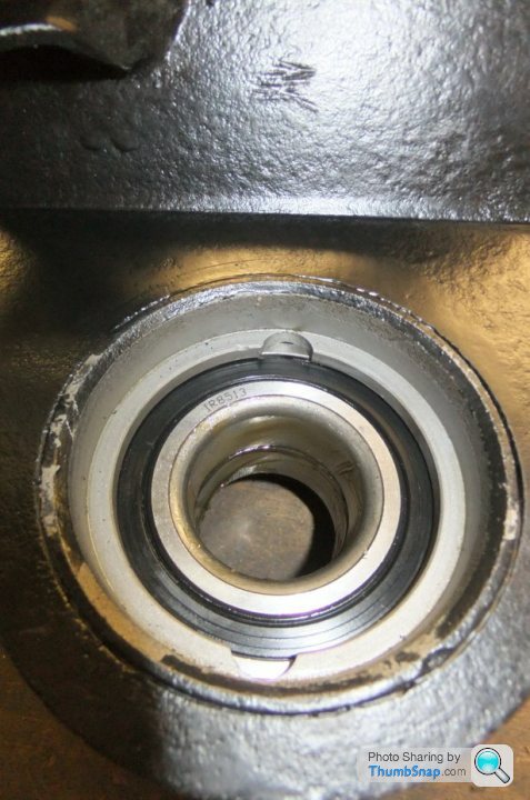
...and hard up against the locating ridge (as viewed from the other side of the hub carrier):
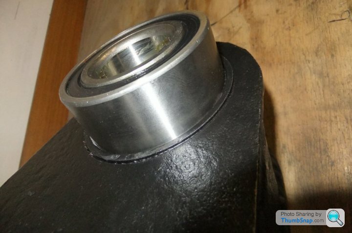
At this point you will need a circlip, preferably a new one but if the old one is in good shape (literally), not corroded or deformed it should be OK for re-use…
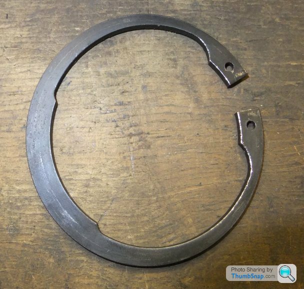
Install the circlip to the groove using the appropriate tool (needle-nosed pliers can be used to good effect on circlips this big).
I find it’s a good idea to tap the circlip around in its groove to make sure it’s seated properly; if it moves from side to side rather than just circumferentially then it’s too small or has been distorted out of shape during fitting:

Next up are the oil seals, inner and outer. This is where the usual Ford wheel bearing kit falls over because on the Granada the inboard and outboard seals were different, whereas TVR used the same type for inner and outer. The one you DON’T need looks like this:
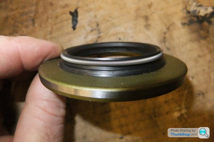
The oil seals have to be a good press fit right from entering the bore so you don’t get much of a lead-in to help get them square. They’re also made from very thin pressed metal that will deform easily so care is needed when installing them.
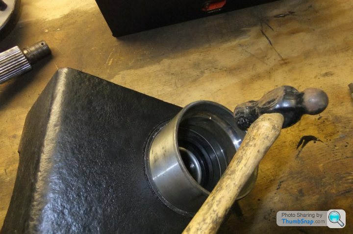
The ideal installation technique is to press the seal in using the old bearing outer shell again:
Lacking an old bearing shell you can use a small hammer and drift around the outer edge of the seal but you do have to watch for the seal entering the bore unevenly or being deformed by the impacts. Also be aware of slipping and damaging the inner lip of the rubber seal as this is the bit that does most of the work!
Aim to initially get the outer face of the seal flush with the surface of the hub carrier all the way around:
and then turn the hub carrier over so you can install the other seal in the same fashion.
The reason I said to initially install the seals flush with the hub carrier faces is that when the driveshaft and hub are installed to the bearing, the inner lips of the oil seals have to seal around the outer faces of shaft and hub.
In service the parts are subjected to water spray and road dirt etc. which leads to surface pitting and wear of the machined surfaces. Ideally you want to position the seals to act on the smoothest area of metal you can find, without the seals’ outer faces being in contact with the rotating parts.
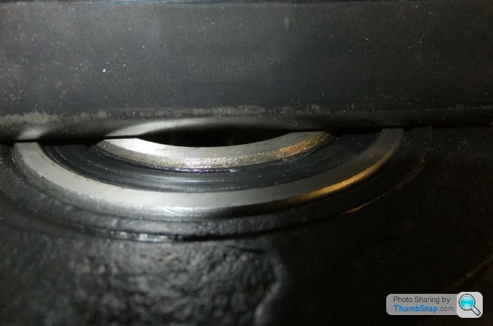
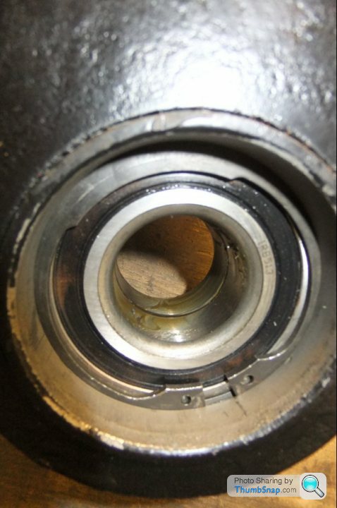
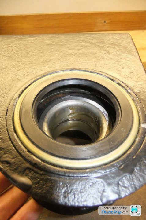
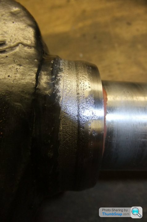
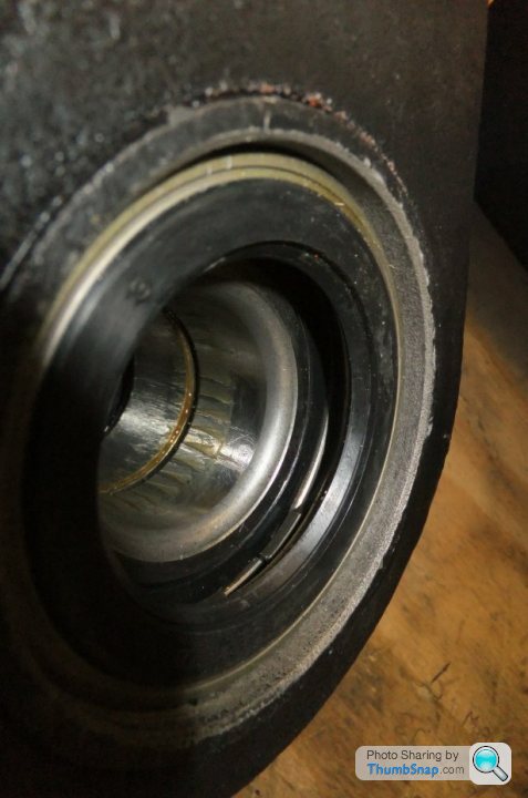
You can see the pitting in this close-up; the thin black line is where the old seal made contact:
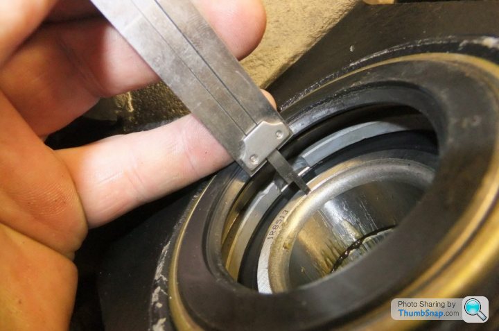
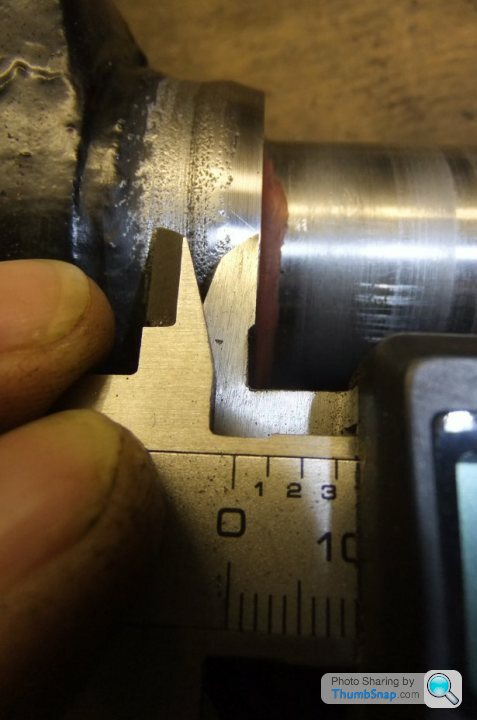
What I did was to measure the distance from the bearing’s inner race (where the driveshaft makes contact with it) to the seal’s inner lip (which was about 15mm) and then measure the contact area on the shaft stub to determine whereabouts I wanted the seal lip to 'sit'… not that I had much choice as you can see.
Then I used the spare bearing shell and a hammer to tap the seal in by a few millimetres so that the lip would be in about the right place…
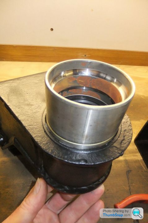
This was repeated for the other seal and the driveshaft installed to check for fit and clearance:
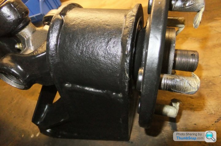
And that’s about all there is to it! As you can see I’d already packed the bearing with grease; the stub splines and thread have been cleaned in readiness for reassembly once back on the car.
You will need one new wheel bearing and one hub carrier
Tarting-up the carrier isn’t essential but adds to the sense of satisfaction.
First make sure the bore of the carrier is undamaged (no dents, score marks etc.) and free from rust and that the circlip groove is similarly sound, with no debris stuck in it. The bore should also be free from grease or oil that might allow the bearing to spin in it.
Ensure the outer surface of the bearing is dry and insert it squarely into the bore…
whereupon you should find it will slip easily a good way in. The outer few millimeters of the bore are slightly larger than the bearing which allows it to be square before you try and press it in.
You can use a big bench vice to drive the bearing in, but I’d modified my simple bench press with a couple of lengths of box section (I originally built it as a bike spring compressor):
and it was a simple matter to position the hub carrier and bearing within it:
Jacking-up the carrier pushes the bearing into the bore…
…until the carrier ‘bottoms’ on the top box-section.
What you then need is a packing piece or spacer to get the bearing the rest of the way in; the ideal instrument is another bearing of the same diameter – or at least the outer race from an old one (I kept this one for such jobs):
Position the spacer/ bearing shell exactly on the outer rim of the new bearing and apply more force…
until the bearing is firmly against the locating ridge inside the carrier bore.
The old bearing shell lifts straight out…
and the bearing will be seen to be sat flush with the inner edge of the circlip groove:
...and hard up against the locating ridge (as viewed from the other side of the hub carrier):
At this point you will need a circlip, preferably a new one but if the old one is in good shape (literally), not corroded or deformed it should be OK for re-use…
Install the circlip to the groove using the appropriate tool (needle-nosed pliers can be used to good effect on circlips this big).
I find it’s a good idea to tap the circlip around in its groove to make sure it’s seated properly; if it moves from side to side rather than just circumferentially then it’s too small or has been distorted out of shape during fitting:
Next up are the oil seals, inner and outer. This is where the usual Ford wheel bearing kit falls over because on the Granada the inboard and outboard seals were different, whereas TVR used the same type for inner and outer. The one you DON’T need looks like this:
The oil seals have to be a good press fit right from entering the bore so you don’t get much of a lead-in to help get them square. They’re also made from very thin pressed metal that will deform easily so care is needed when installing them.
The ideal installation technique is to press the seal in using the old bearing outer shell again:
Lacking an old bearing shell you can use a small hammer and drift around the outer edge of the seal but you do have to watch for the seal entering the bore unevenly or being deformed by the impacts. Also be aware of slipping and damaging the inner lip of the rubber seal as this is the bit that does most of the work!
Aim to initially get the outer face of the seal flush with the surface of the hub carrier all the way around:
and then turn the hub carrier over so you can install the other seal in the same fashion.
The reason I said to initially install the seals flush with the hub carrier faces is that when the driveshaft and hub are installed to the bearing, the inner lips of the oil seals have to seal around the outer faces of shaft and hub.
In service the parts are subjected to water spray and road dirt etc. which leads to surface pitting and wear of the machined surfaces. Ideally you want to position the seals to act on the smoothest area of metal you can find, without the seals’ outer faces being in contact with the rotating parts.
You can see the pitting in this close-up; the thin black line is where the old seal made contact:
What I did was to measure the distance from the bearing’s inner race (where the driveshaft makes contact with it) to the seal’s inner lip (which was about 15mm) and then measure the contact area on the shaft stub to determine whereabouts I wanted the seal lip to 'sit'… not that I had much choice as you can see.
Then I used the spare bearing shell and a hammer to tap the seal in by a few millimetres so that the lip would be in about the right place…
This was repeated for the other seal and the driveshaft installed to check for fit and clearance:
And that’s about all there is to it! As you can see I’d already packed the bearing with grease; the stub splines and thread have been cleaned in readiness for reassembly once back on the car.
Edited by Wedg1e on Monday 17th November 03:08
adam quantrill said:
>> Lacking an old bearing shell <<
Like the one you just took out? ;^)
I have seen them split in two by the time they've come out Like the one you just took out? ;^)
I have another old one (twin to the one in the pics) that has lots of weld built-up inside it; that was the only way I could persuade it to part company with the alloy carrier (it was on my Tasmin).
Edit for typo

Edited by Wedg1e on Monday 17th November 23:19
RCK974X said:
Nice, BUT mine doesn't look remotely like that - I have the aluminium moulding with 4 bolts....
Is that (the ally one) supposed to be the really tough one to do ?
Asking as mine came out fairly easily, and I didn't need a big press, just some very careful hammer work....
Pretty well the same principle though; the difficulty can be in getting the hub carrier off the rest of the suspension! The 4 bolts retain the carrier to the trailing arm and they're not usually a problem, it's the long bolt through the tie-rod and shock lower eye that tend to give trouble.Is that (the ally one) supposed to be the really tough one to do ?
Asking as mine came out fairly easily, and I didn't need a big press, just some very careful hammer work....
One technique I have seen to remove stubborn bearings from alloy hub carrier castings (might have been on a Jag) was to put the whole thing with the bearing still in-situ, into a hot oven for an hour.
Then whip it out and drop a bag of ice into the centre of the bearing (usually by that time the bearing has had its inner races and balls knocked out anyway!). The thermal shock can cause the bearing shell to either crack or shrink just enough to allow it to be tapped out.
As I said in the earlier post, one technique I've used was to knock the inner races and balls out, then build-up two ridges of weld around the central ridge of the outer shell (on which the balls ride)... this presents you with a large surface area to impact with a drift and reduces the risk of scoring the bore wall whilst trying to hit the bearing's outer perimeter.
Incidentally that's what the two half-moon shaped cutouts are for in the bore: they allow you to apply a drift to a small area of the outer shell. Unfortunately it may not be enough in itself and that's when you have to get creative


Press or hammer, either works: the press tends to be less liable to cause damage if anything slips but needs more setup and initial investment, I guess. I've used a big vice in the past as another alternative.

KKson said:
I have read that as bearings can be marginally different in size then the packings from brake disc to drive shaft might need adjusting to stop lateral pressure on the shaft and hub. Not sure if this is true?
The shims between disc and driveshaft set the wheel camber so adding or taking away from the stack will change the wheels' 'tilt'.Could the squeak be down to drag from the rear brake pads?
Gassing Station | Wedges | Top of Page | What's New | My Stuff