In tank fuel pump retrofit. The worrying bit!
Discussion


High Graham. Was just reading your posts on le mans thread and reminiscing about our trip. Hope to go next year if car is together again.
separate hp pump in each tank with built in surge control. Also using speed control to combat the overheating fuel problem that I have been plagued with ever since converting to EFI.
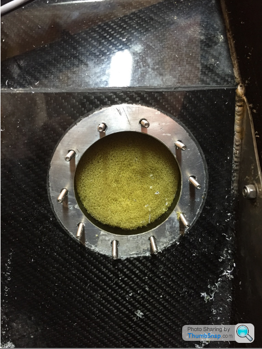
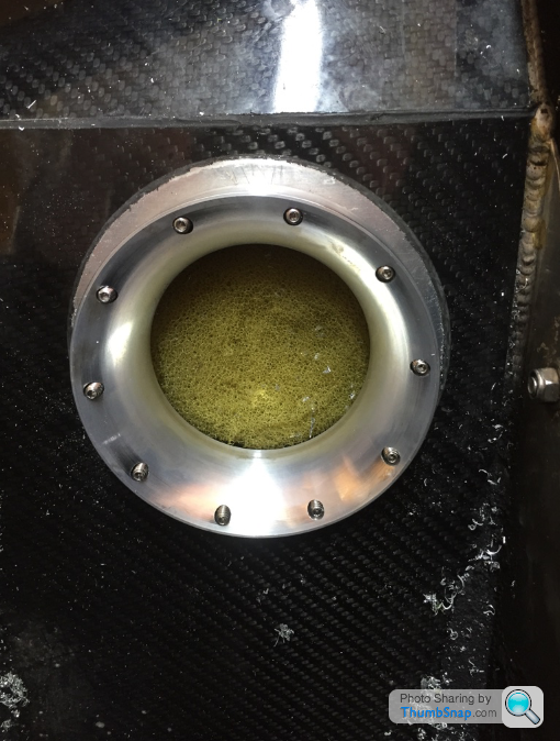
Because of the size of the pump flange I have had to put it in the sloping side of the tank which makes in situ drilling a little tricky but so far so good!
separate hp pump in each tank with built in surge control. Also using speed control to combat the overheating fuel problem that I have been plagued with ever since converting to EFI.
Because of the size of the pump flange I have had to put it in the sloping side of the tank which makes in situ drilling a little tricky but so far so good!

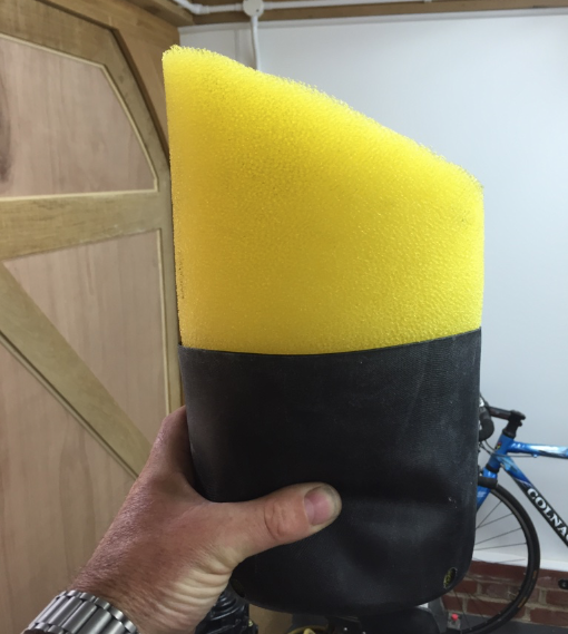
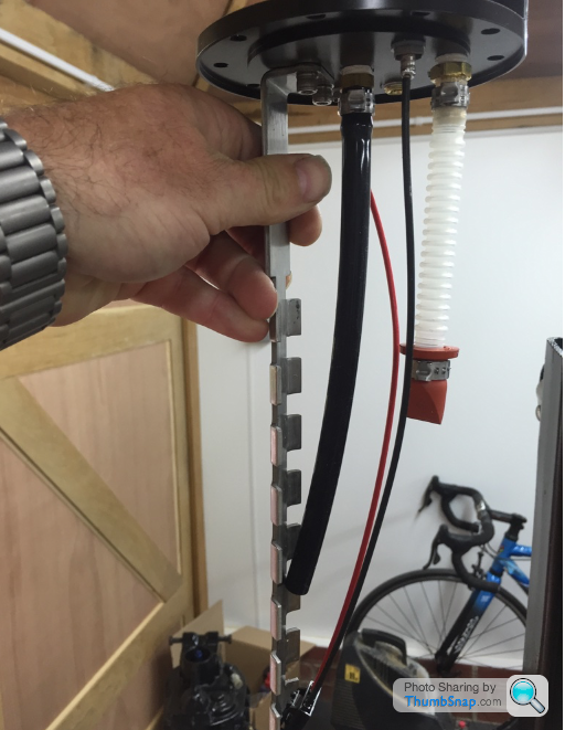
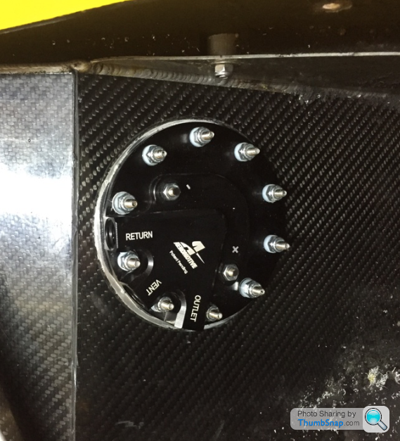
Pics self explanatory I guess. Tank was emptied and then filled to brim with water to prevent hazards! Water drained and dried out. Fitting at an angle not particularly easy but doable. decent right angle drill required. Note rubber bucket which sits on bottom of tank with 4 small holes to reduce drain out under heavy g loads. Pump positioned as far back as poss and in centre of tank so g forces of acceleration and cornering will have min effect. Decel is off throttle. Tanks now completely separate with 2 pevekoil 3 port valves to control flow and return.
Pump/gauge changeover in cockpit swaps tanks as before. Supply from speed/pressure controller to pumps is swapped with 4 pole relay also with same cockpit switch. Simples
Bog
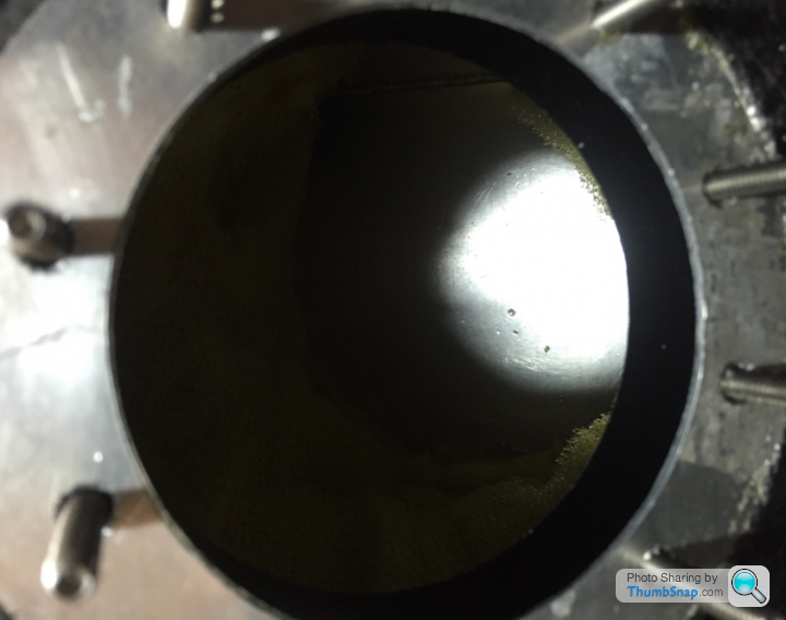
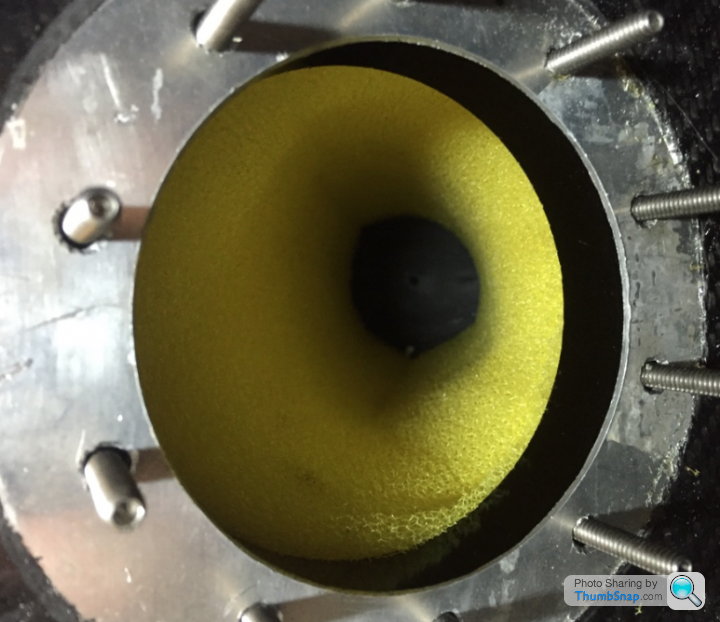
Not very scientifically. The foam was soaked with it but overnight it all dropped into bottom of tank. Hole is quite big (3.25 inches) and quite a bit more foam cut out so I was able to soak it up with kitchen towel. remember that there is always small amounts of water in fuel. I intend to fill with petrol and then pump out and allow any thing left to separate out before refilling.
Filling with water is the recommended way to do any work on a tank that has had fuel in it before.
Agreed Paul. Removing tanks is an unnecessary hassle and expense. It was your system that got me started on doing the conversion but I was not keen to loose the 2 tank system and so came up with my solution. Fitting the in tank pump took under 2 hours and can be done by any half decent DIYer. Not only does it solve the cavitation problems that some are experiencing but it also removes a whole load of pipe work from the very cramped engine bay particularly in an LS powered car. This has positive implications for safety and aesthetics as well as removing the very real potential for engine damage due to the extremely weak fuel mixtures encountered when cavitation occurs.(often weak enough to cause the engine to stop altogether)
It is a blessing for those who experience this that the nature of the problem experienced in our cars is that it usually occurs at low throttle opening after prolonged periods sat in traffic etc.
It is probably completely unnecessary to add the pump speed/pressure controller with this system but I do not see the point of having a fuel pump (or 2) which pumps 300 litres/hr continually pumping at that rate when 95% of the time we are probably consuming in the region of 10 litres/hr.
A bit of research into how all high performance production cars overcome these problems turns up that they all now use in tank pumps with speed control all of which is built into the engine ECU. In fact GM ecu's of later design have this facility built in with a solid state fuel pump relay which produces a PWM current to the fuel pump. Aftermarket ECU's are now being produced with this facility as well following the surge in EFI conversions which are happening especially in the US hot rod market.
Pump kit @ £400 available in UK.
Lack of space especially in LS cars combined with the amount of fuel hoses running all over the place does seem to contribute to the problem so one has to conclude that heat absorption is part of the problem. However curing that problem with confidence could/would cost at least as much. Do not overlook the amount of work done by the HP pump to pump this amount of fuel around and around the system. It does cause an increase in fuel temp. The main issue I believe is the restriction in the supply pipe to the HP pump. This causes very low pressure at the point of suction. Enough to cause cavitation in some cases. Fuel pump manufacturers recommend bigger pipe and as shorter length as possible for the feed to the HP pump. The possibility of cavitation increases as temperature rises and pressure drops. The design of this pipe is critical to the correct running of external pump systems.
The internal pumps have no supply pipe obviously and a large intake port.
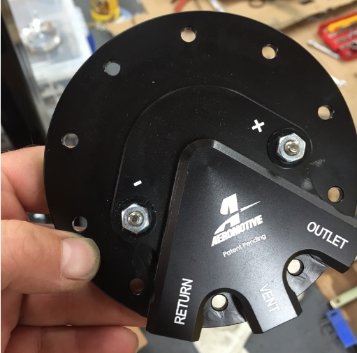
Please note before purchase that not all pumps are suitable for PWM control. Bosch 044 is. I have a 340l/hr aeromotive in tank pump here brand new that also is and is surplus to requirements. Think it is the same as Paul has fitted and will fit through fuel level sender hole if thats the way you want to go. DYOR!
I have to say that the controller looks very well made and is suitable for engine bay mounting i.e. fully potted.
I have to say that the controller looks very well made and is suitable for engine bay mounting i.e. fully potted.
Depends on how you want to do it. For instance I am going to run 2 hp pumps. 1 in each tank I am using 2 peveekoil metal bodied solenoid valves to change over flow and return. One speed control system with a DPDT relay to swap, valves, gauges and pumps from one tank to another. I can price it for you but you may choose a different spec. Happy to talk about my choice and why I made it.
I would like to stress that I am not knocking the factory system in any way I have just chosen to do things differently following my experiences.
I would like to stress that I am not knocking the factory system in any way I have just chosen to do things differently following my experiences.
Not sure if anybody else is going to install the pump controller. Following the install of one (not by myself but based on my recommendation) yesterday. I have discovered a slight problem with it.
The controller uses PWM on the negative side of the pump to control the speed/pressure. It is imperative to check that the pump body is not connected to the negative terminal and if it is the pump body must be isolated from any connection to ground. This may include a path to ground through the braiding on the fuel lines as well as obvious bolts to chassis. The in tank pump kit that I am using specifically isolates the pump from the tank. At this time it appears that the Bosch 044 body is connected to the negative terminal. A simple rubber sleeve around the pump to isolate the brackets should cure the connection to the chassis. Not yet sure if the pipe braiding is an issue!!
The controller uses PWM on the negative side of the pump to control the speed/pressure. It is imperative to check that the pump body is not connected to the negative terminal and if it is the pump body must be isolated from any connection to ground. This may include a path to ground through the braiding on the fuel lines as well as obvious bolts to chassis. The in tank pump kit that I am using specifically isolates the pump from the tank. At this time it appears that the Bosch 044 body is connected to the negative terminal. A simple rubber sleeve around the pump to isolate the brackets should cure the connection to the chassis. Not yet sure if the pipe braiding is an issue!!
Problem now solved. unit working perfectly. Fuel pump body was touching body panelling causing a different earth route. Interestingly & surprisingly the braided fuel lines are not causing a problem (maybe only because anodising acts as an insulator).
I am not sure if all PWM units work on the negative. There may be an electronic reason for it because all of the ECU's that I have worked with do the same i.e. they switch the earth connections off and on for the injector pulses and switch relays using the negative. Electrician yes but electronics not my forte!
If braid becomes a problem. Easy enough to pull back a bit at pump connections and heat shrink to isolate from pump.
Edited by MarkWebb on Tuesday 14th July 10:56
Gassing Station | Ultima | Top of Page | What's New | My Stuff