The ebay generator restoration thread
Discussion


Recently I started buying non running generators on ebay, fixing them and re-selling (bit like Wheeler Dealers) to try and earn a few extra beer tokens and because I enjoy tinkering with engines and things like this.
I started off with a single cylinder 5kva Diesel that wouldn’t start. After removing the case I found the problem with the starter motor.
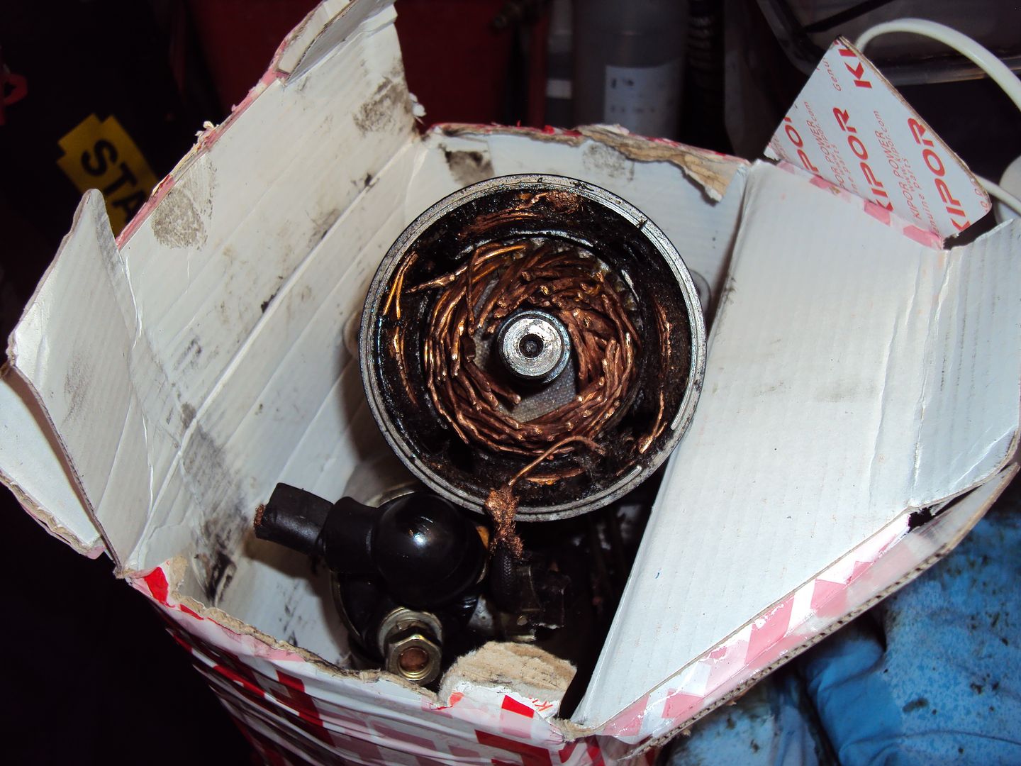
The commutator was completely destroyed.
A new started was fitted and the generator fired up straight away. While replacing the starter motor I noticed the AVR module was also damaged.
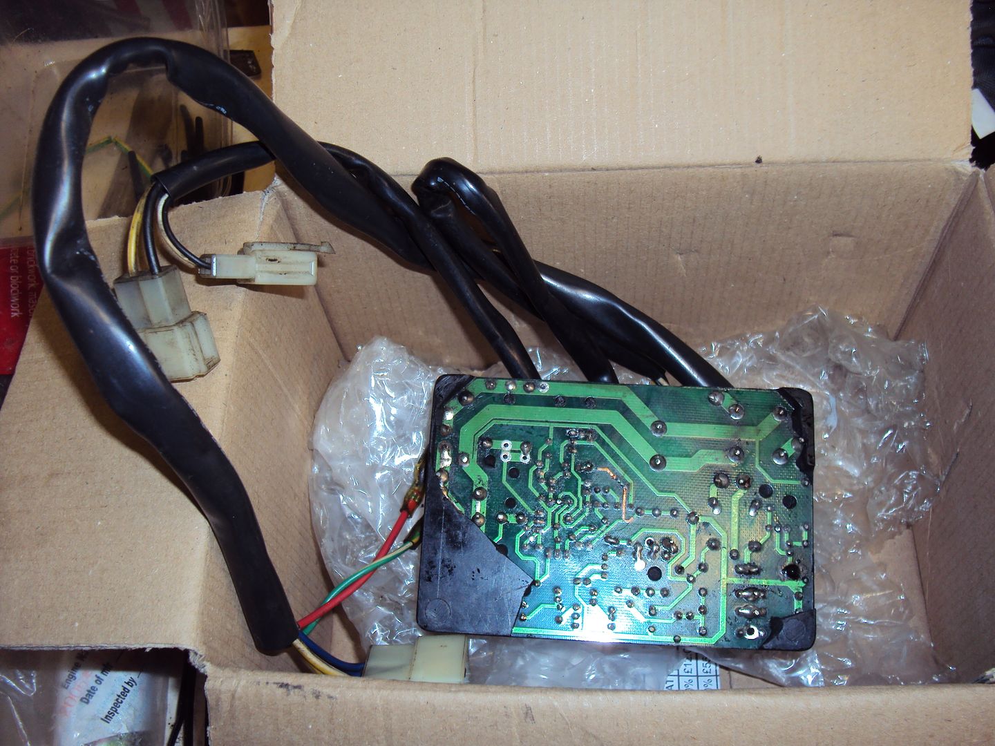
The circuit board should be covered in the black potting to protect it, also there is a damaged track visible. The AVR was working, but I decided to replace it for piece of mind.
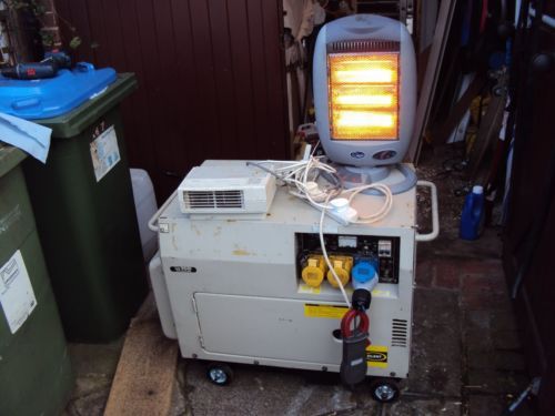
The finished working generator
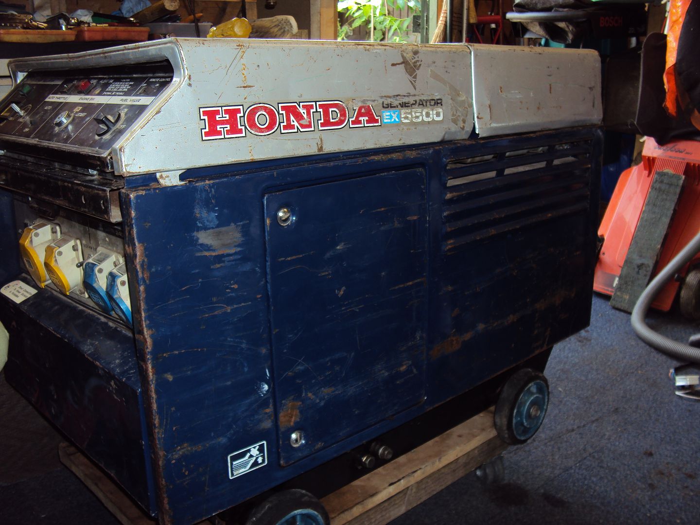
The latest project is 5kva Honda with a 300cc 2 cylinder petrol engine.
Photos from ebay listing:
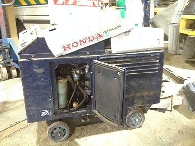
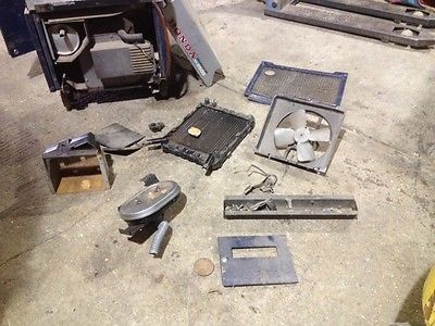
I contacted the seller and found that they had sent it away for repair but decided not to go ahead so it came back as a kit of parts. I did a bit of research and found this particular model had a weak oil pump, so guessed based on the disassembly that the oil pump was the likely problem.
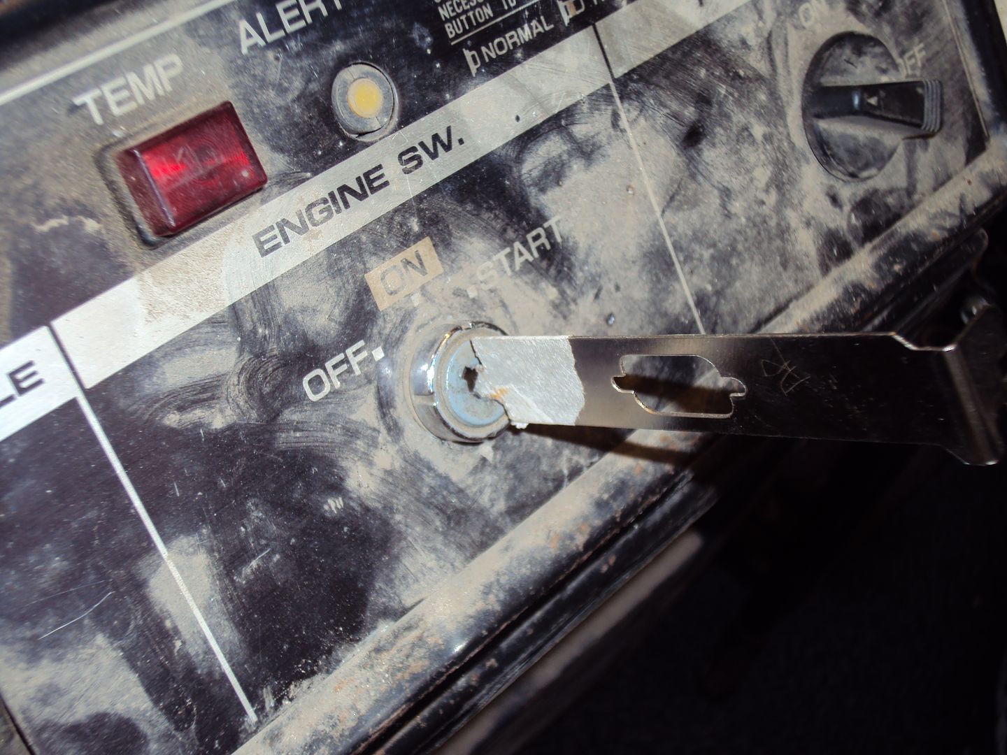
On collecting it I found that it was missing the key for the starter, fortunately the seller had couple of identical generators, so I took a picture of the keys against one of my keys for scale.
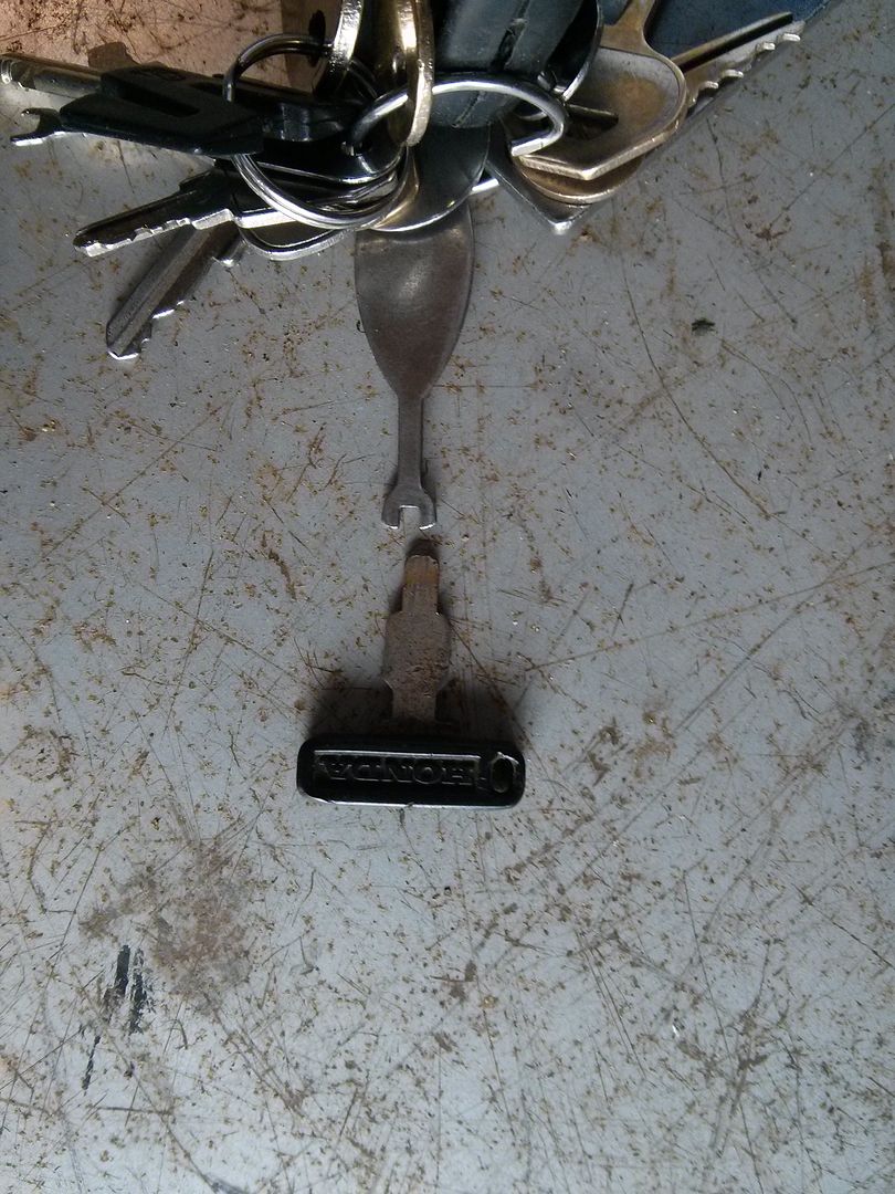
I made a copy of the key out of an old PC expansion slot cover by working the scale from the photo
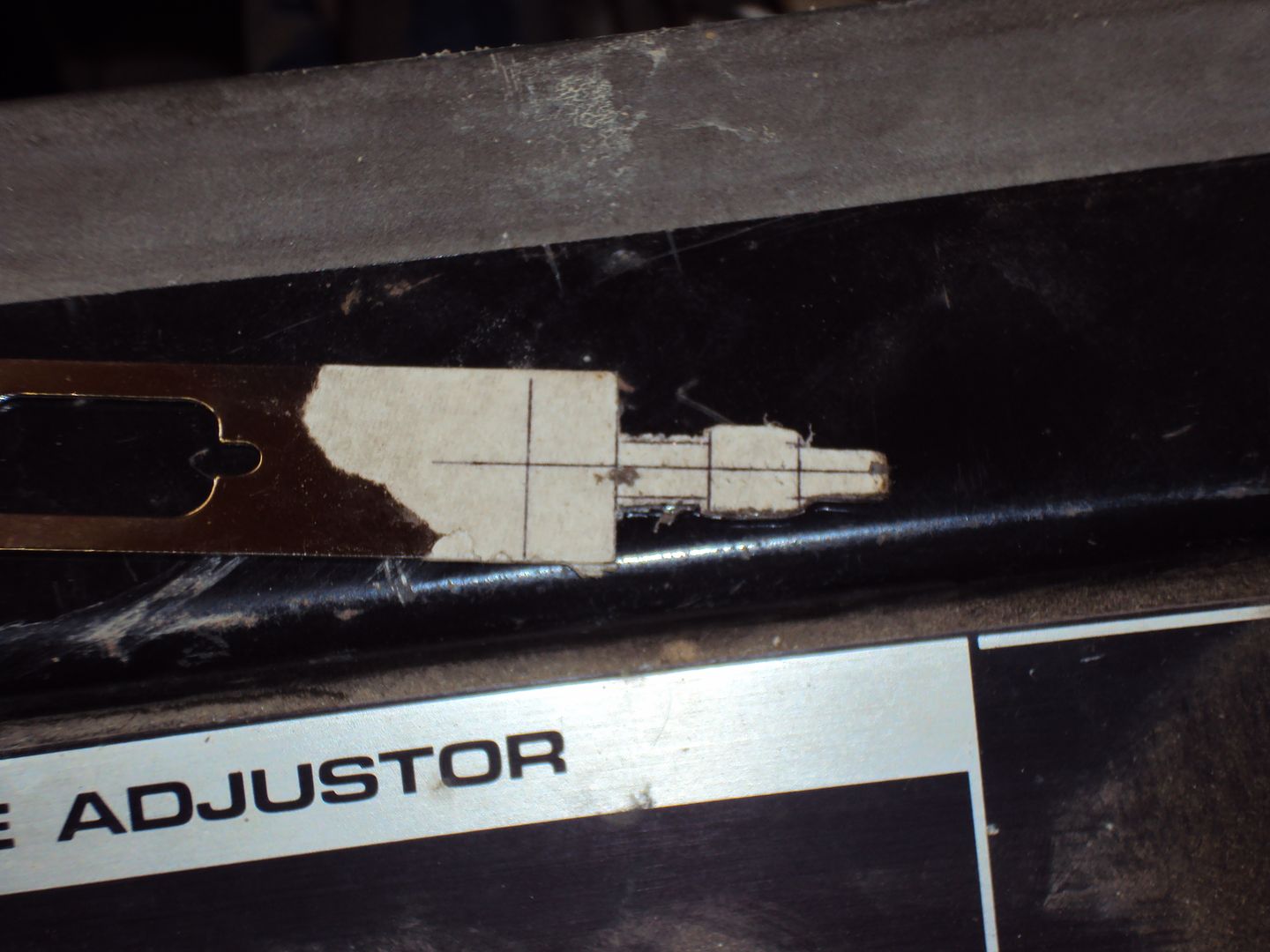
And it worked
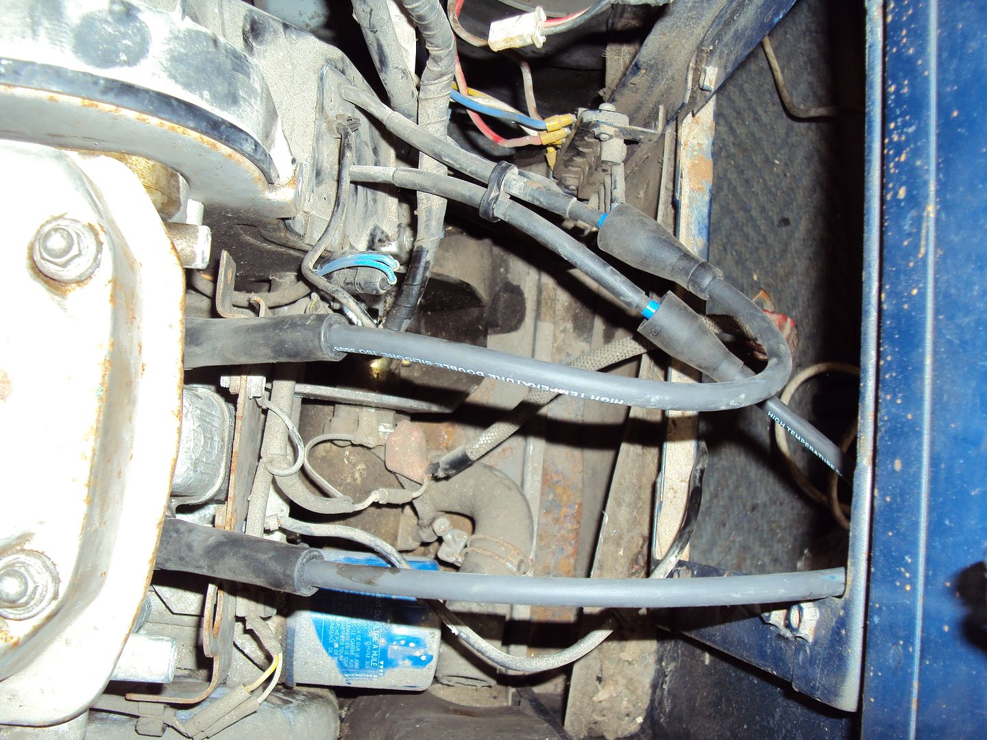
Before I could start the engine to diagnose the fault I had to repair the magneto as someone had helpfully cut the spark plug caps off
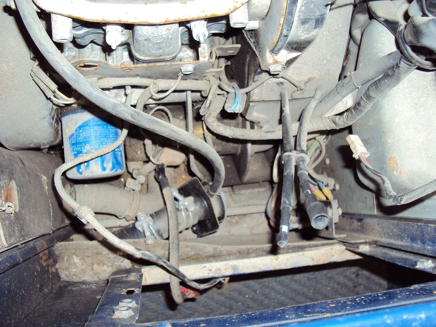
I cranked the engine over with the sparkplugs removed to check the magneto still worked, which it did. There was nice healthy spark which jumped about 5mm, this proved the magneto was ok. I managed to get a couple of short spark plug leads from a local motor factors and attached them to what was left of the leads on the magneto.
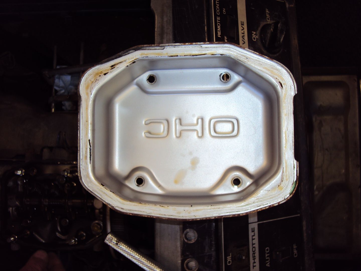
Opened up the rocker cover to check the valve gear, all looked fine.
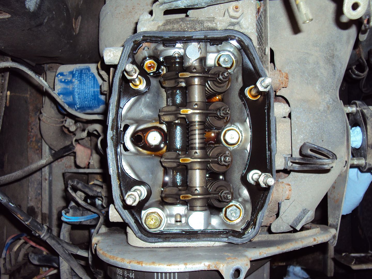
Inside of rocker cover all nice and clean
After reassembling everything I got the engine started and running for about 10 seconds before it cut out due to low oil pressure. I confirmed the lack of oil pressure by replacing the oil pressure switch with a pressure gauge which read 0 with the engine running.
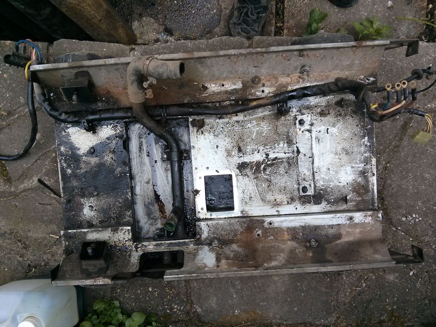
So the disassembly begun with the removal of the outer case
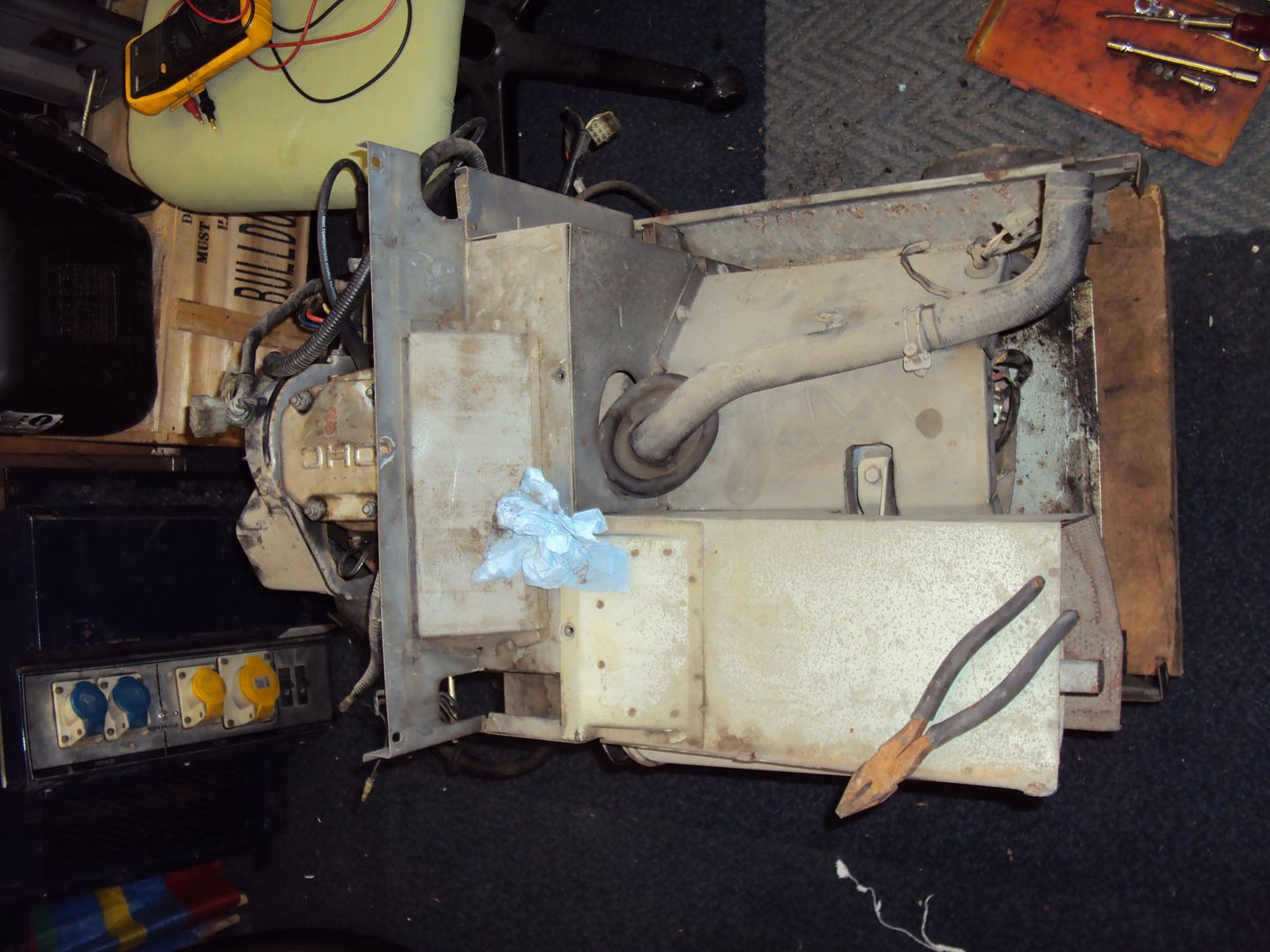
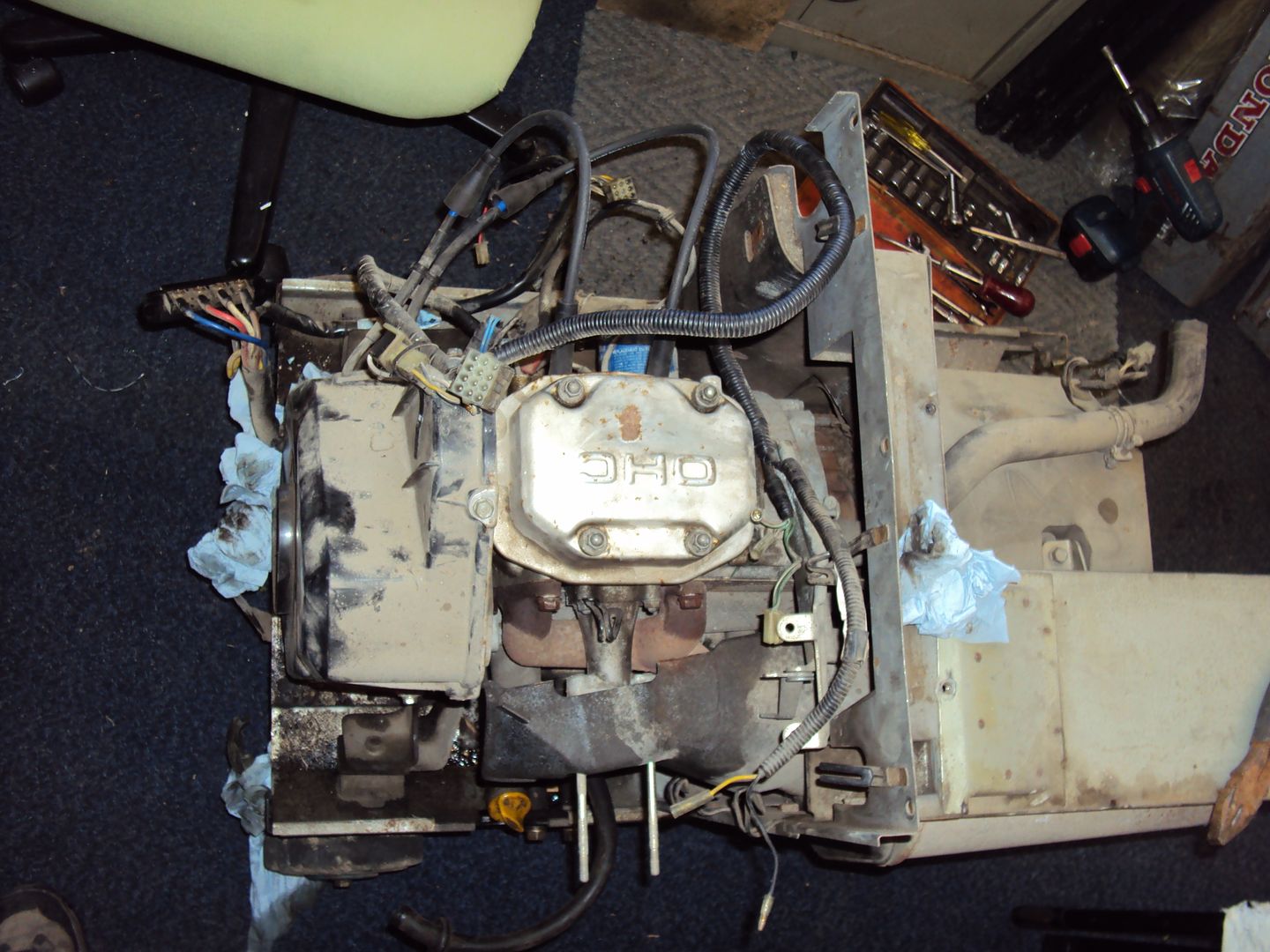
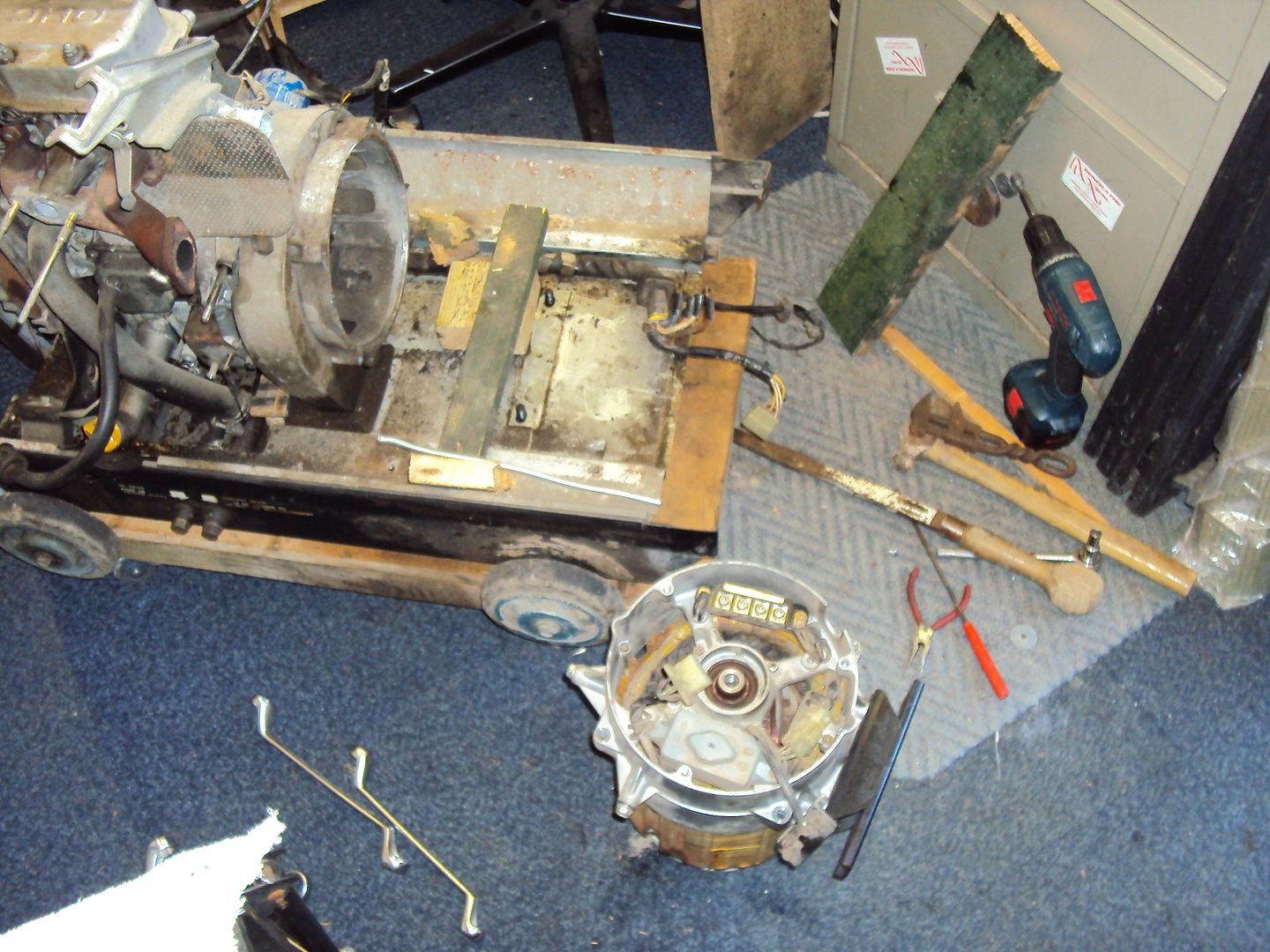
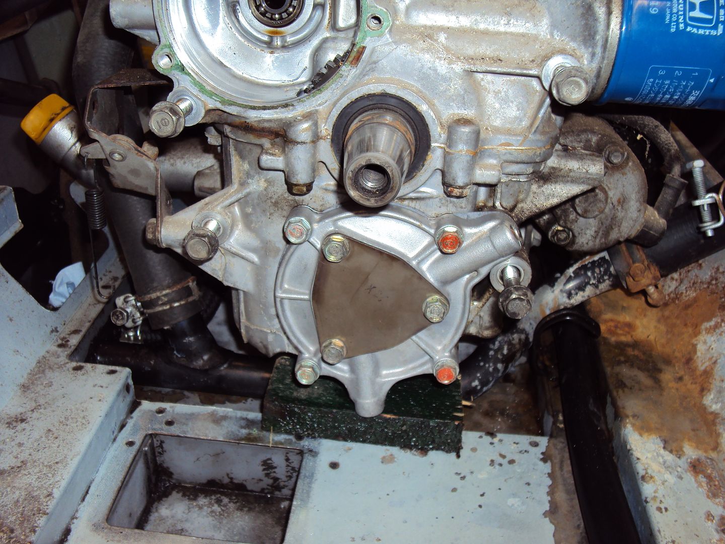
Where it stands today, all covers and exhaust removed
The next step is to disassemble and remove the alternator so I can get access to the oil pump to replace the drive gear.
I started off with a single cylinder 5kva Diesel that wouldn’t start. After removing the case I found the problem with the starter motor.
The commutator was completely destroyed.
A new started was fitted and the generator fired up straight away. While replacing the starter motor I noticed the AVR module was also damaged.
The circuit board should be covered in the black potting to protect it, also there is a damaged track visible. The AVR was working, but I decided to replace it for piece of mind.
The finished working generator
The latest project is 5kva Honda with a 300cc 2 cylinder petrol engine.
Photos from ebay listing:
I contacted the seller and found that they had sent it away for repair but decided not to go ahead so it came back as a kit of parts. I did a bit of research and found this particular model had a weak oil pump, so guessed based on the disassembly that the oil pump was the likely problem.
On collecting it I found that it was missing the key for the starter, fortunately the seller had couple of identical generators, so I took a picture of the keys against one of my keys for scale.
I made a copy of the key out of an old PC expansion slot cover by working the scale from the photo
And it worked
Before I could start the engine to diagnose the fault I had to repair the magneto as someone had helpfully cut the spark plug caps off
I cranked the engine over with the sparkplugs removed to check the magneto still worked, which it did. There was nice healthy spark which jumped about 5mm, this proved the magneto was ok. I managed to get a couple of short spark plug leads from a local motor factors and attached them to what was left of the leads on the magneto.
Opened up the rocker cover to check the valve gear, all looked fine.
Inside of rocker cover all nice and clean
After reassembling everything I got the engine started and running for about 10 seconds before it cut out due to low oil pressure. I confirmed the lack of oil pressure by replacing the oil pressure switch with a pressure gauge which read 0 with the engine running.
So the disassembly begun with the removal of the outer case
Where it stands today, all covers and exhaust removed
The next step is to disassemble and remove the alternator so I can get access to the oil pump to replace the drive gear.
s3fella said:
Quite 'niche geeky' but captivating reading nonetheless!
How do you know so much about gennies? Do you work in similar field or just read a few books?
I'd imagine you could make a good few quid on stuff like this, that Honda will be worth what, a grand plus when done?
Post more pics and projects, it's weirdly very interesting!
I’m learning as I go, my background is electronics so a bit smaller than this and a lot cleaner. How do you know so much about gennies? Do you work in similar field or just read a few books?
I'd imagine you could make a good few quid on stuff like this, that Honda will be worth what, a grand plus when done?
Post more pics and projects, it's weirdly very interesting!
When working they tend to go for £4-600, I might tidy up the paintwork with a fresh coat of blue and silver to make it look a bit less beaten up.
Today’s progress
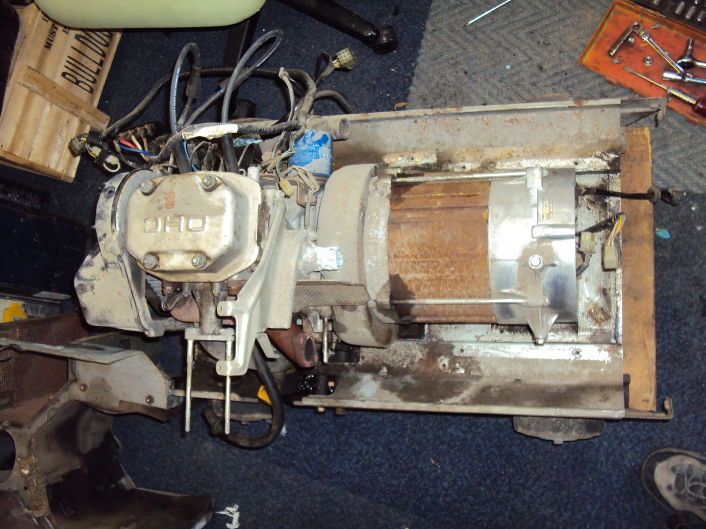
Managed to separate the alternator and engine.
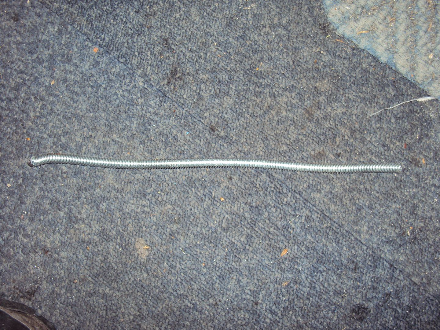
Had push the alternator off the engine shaft using a piece of threaded bar which was placed in a hole which runs through the centre of the alternator shaft. A second bolt was used to push against the rod, had to hammer the rod out of the alternator shaft once it was released as ended up getting a bit bent.
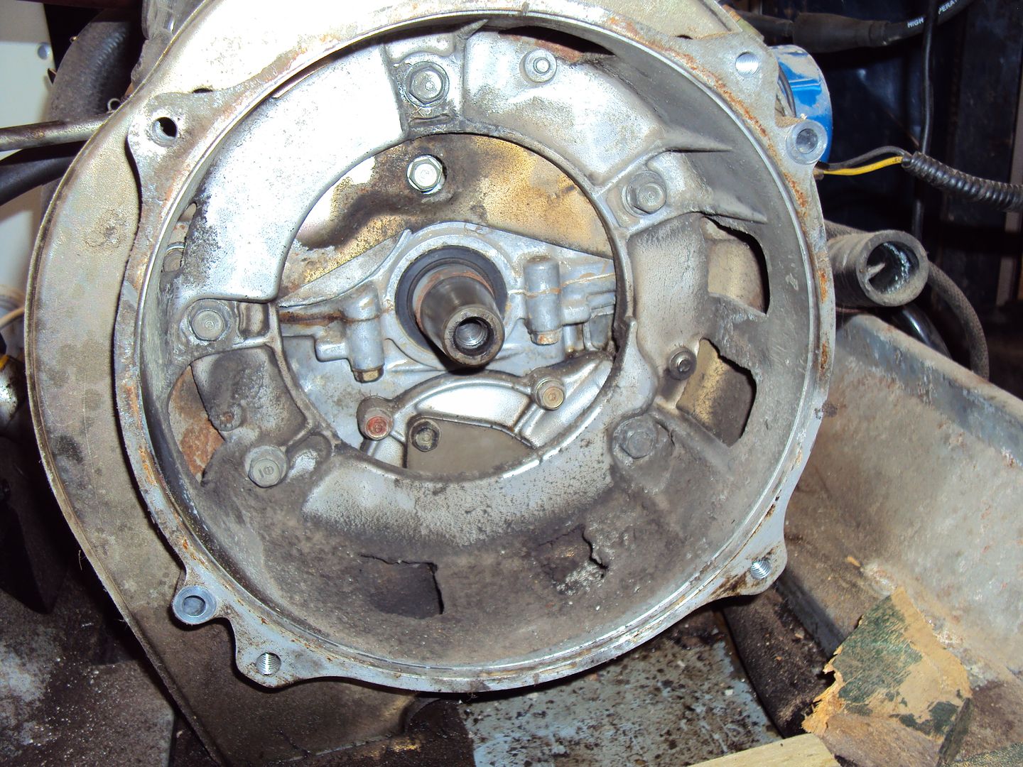
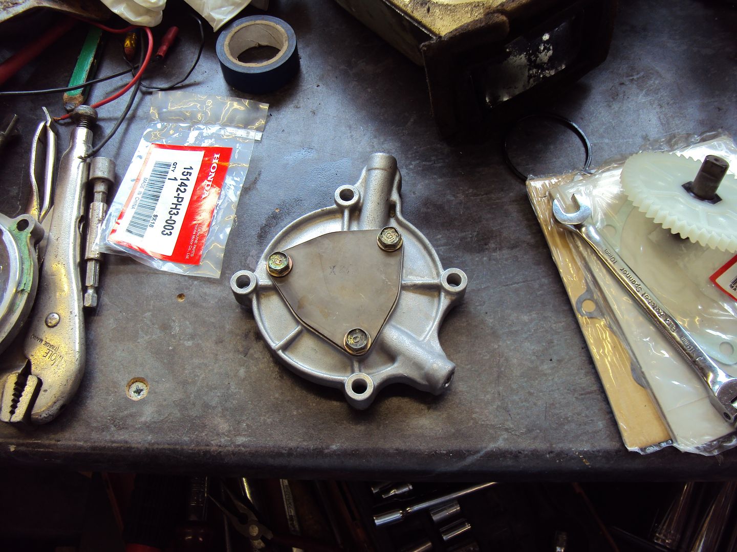
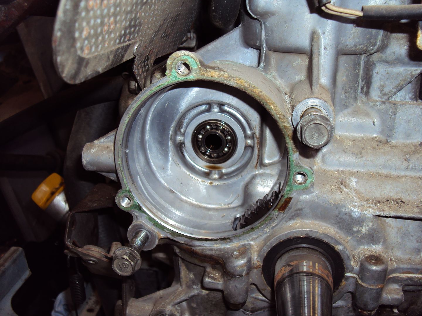
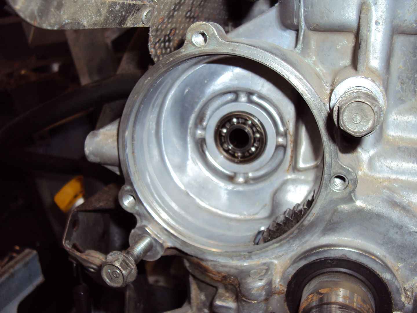
Nearly there, the oil pump is behind the cover just below the engine shaft.
Managed to separate the alternator and engine.
Had push the alternator off the engine shaft using a piece of threaded bar which was placed in a hole which runs through the centre of the alternator shaft. A second bolt was used to push against the rod, had to hammer the rod out of the alternator shaft once it was released as ended up getting a bit bent.
Nearly there, the oil pump is behind the cover just below the engine shaft.
s3fella said:
Threaded rod trick is genius! Remembering that.
Not sure why this thread is so captivating, but it's is, so keep up the detailed progress pics, op.
The threaded rod method came from this guy http://www.petepower.co.uk/ he has been very helpful and is sorting the parts for me.Not sure why this thread is so captivating, but it's is, so keep up the detailed progress pics, op.
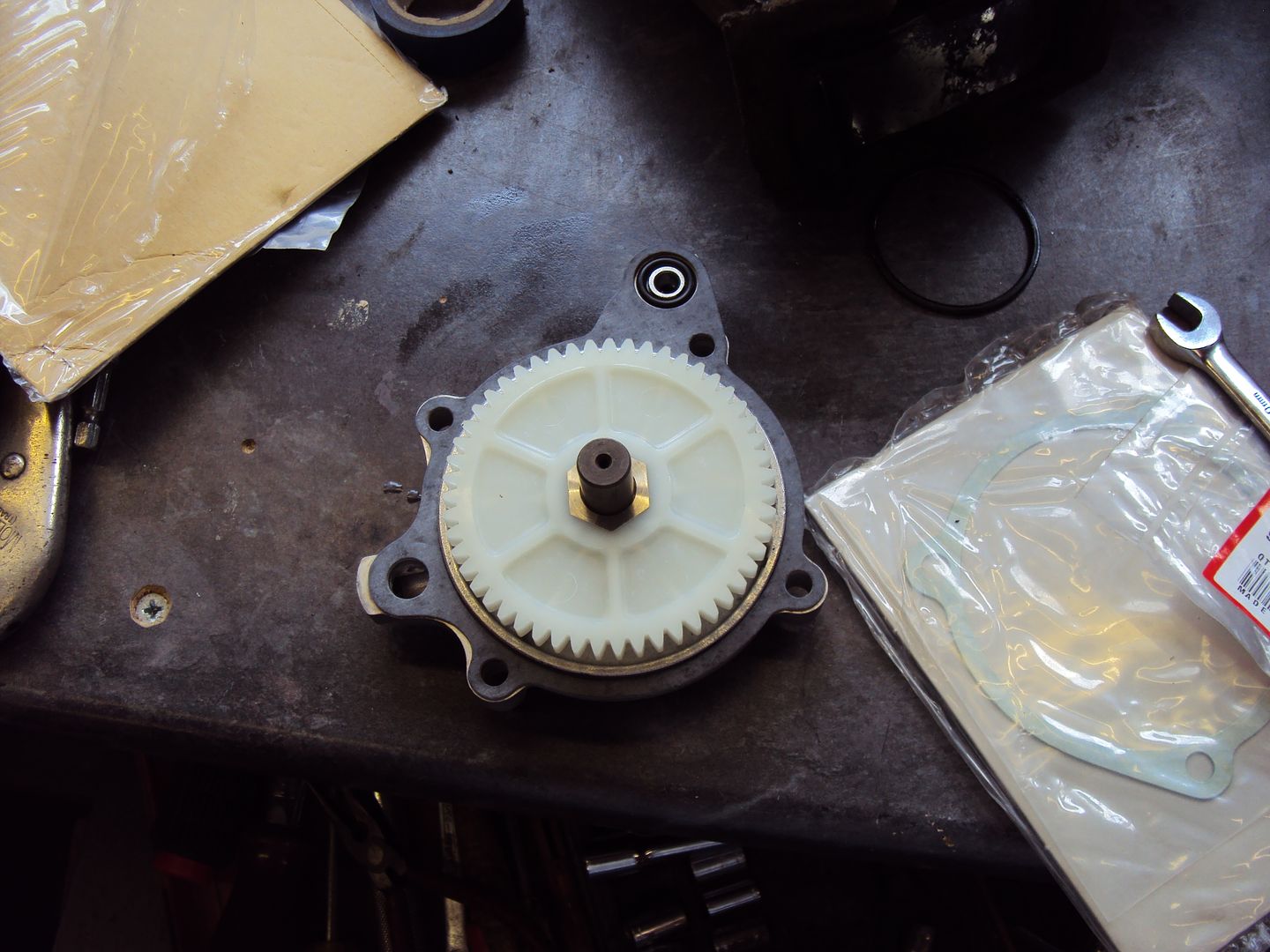
Got to the oil pump drive today, as expected it was completely devoid of teeth.
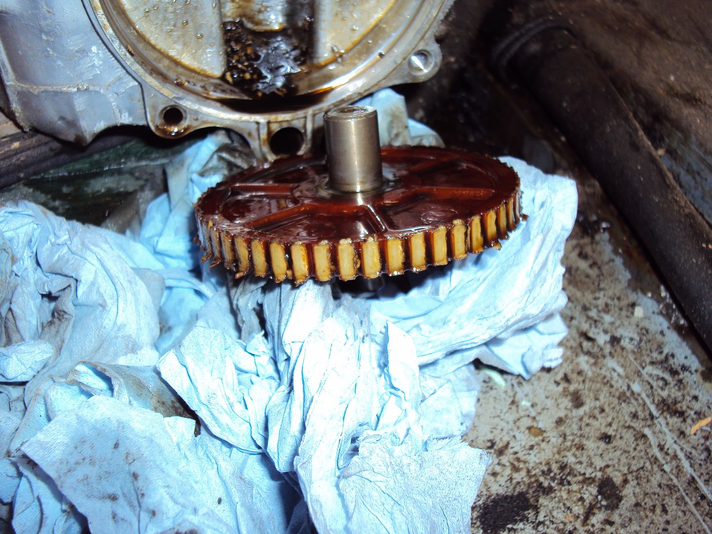
Lots of bits of teeth in the bottom of the drive gear housing
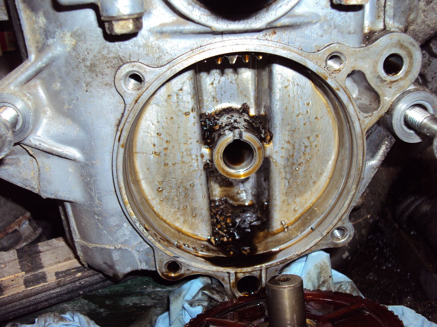
Also found these 2 bent pins, probably what caused the problem.
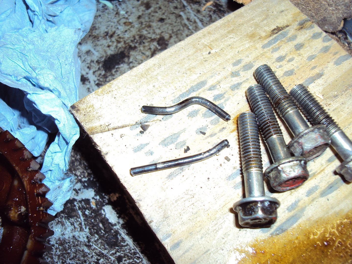
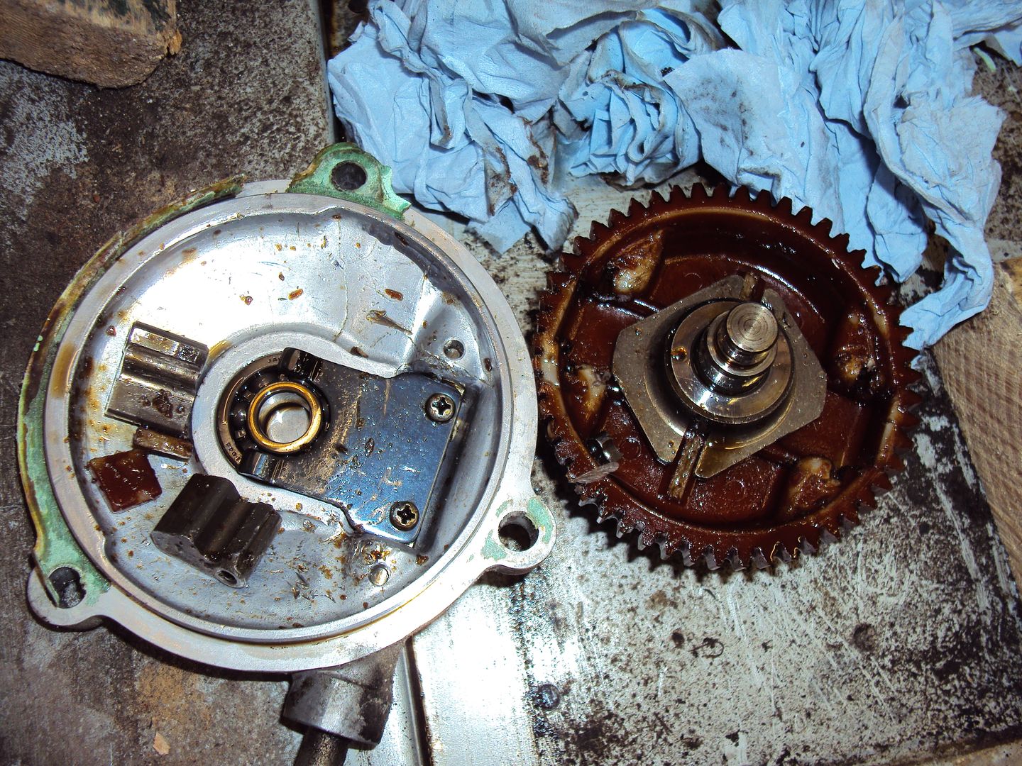
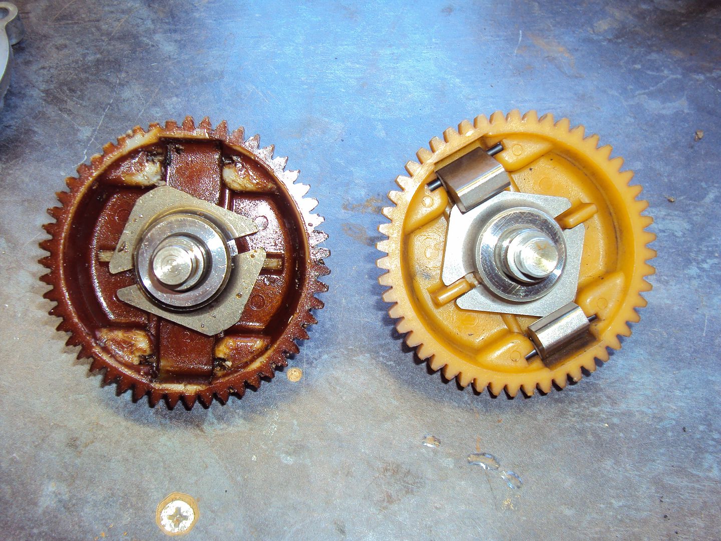
It turns out the pins are part of the governor assembly, the pins support 2 weights which act against a plate which in turn operates the throttle via a lever. The weights in the housing (left) should be attached to the gear (right) with the pins.
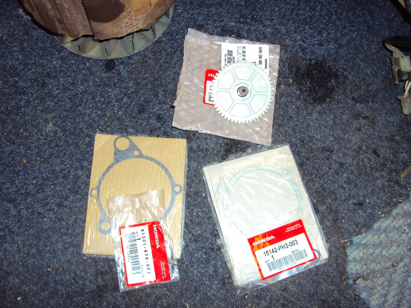
New parts have arrived consisting of oil pump drive gear, 2x O-rings for oil pump, oil pump gasket and governor housing gasket.
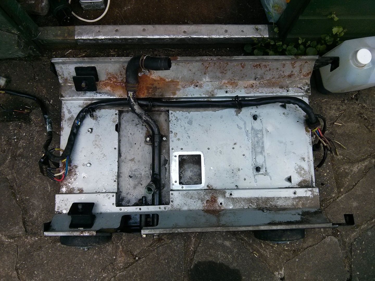
While I was waiting for the parts to arrive, I removed the engine to clean the chassis.
Before
After a bit of work with the power washer & engine and machine cleaner
Oil pump cleaned up and re-built with new O-rings
Back on engine
I cranked the engine with the starter, after about 10 second the oil warning light went out, so all is good.
Just waiting on the replacement governor to arrive, managed to find a used one ebay in the USA for 20.38 including shipping!
The last job was to remove the remnants of the governor housing gasket.
All cleaned up
The governor should arrive sometime next week, so hopefully it should be up and running by the following weekend
creationracing said:
Great stuff and good bargain hunting!
I'm just away to plumb in one of these to my house:
http://www.cheapmowers.com/acatalog/Briggs---Strat...
So I might come asking for one of your cheap do-er uppers!
Thanks, My Dad has just fitted something similar to his houseI'm just away to plumb in one of these to my house:
http://www.cheapmowers.com/acatalog/Briggs---Strat...
So I might come asking for one of your cheap do-er uppers!
http://www.ebay.co.uk/sch/i.html?_trksid=p3984.m57...
The replacement governor finally arrived after spending 7 days in a US customs warehouse, Looks a bit better than the broken one.
While I was waiting for the governor I cleaned up some of the parts
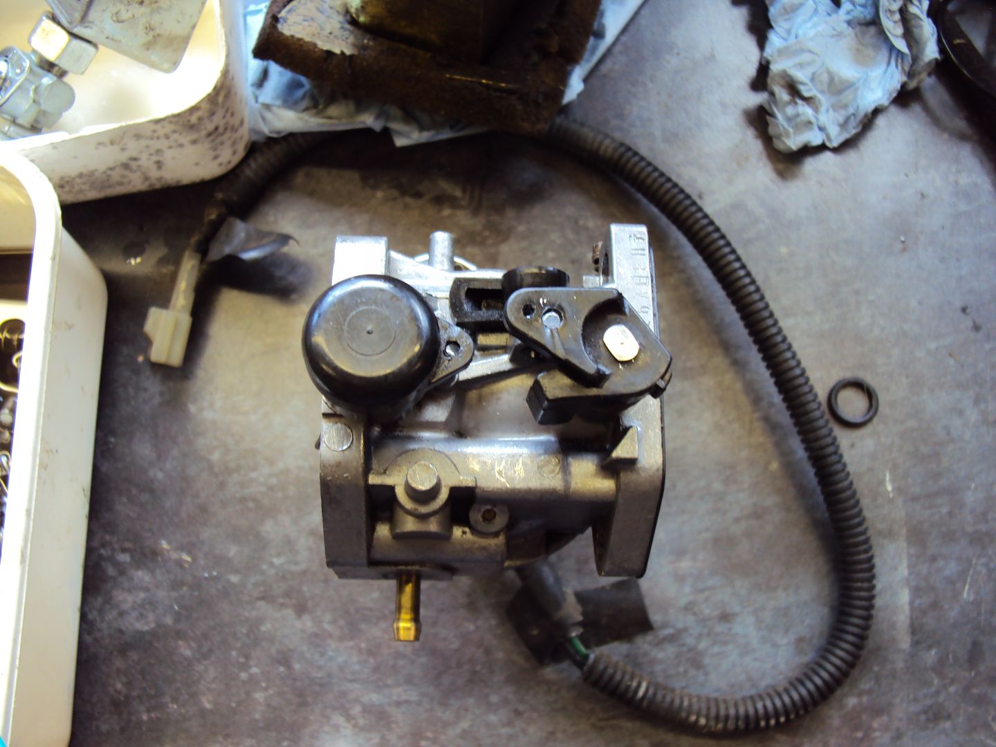
carburettor before:
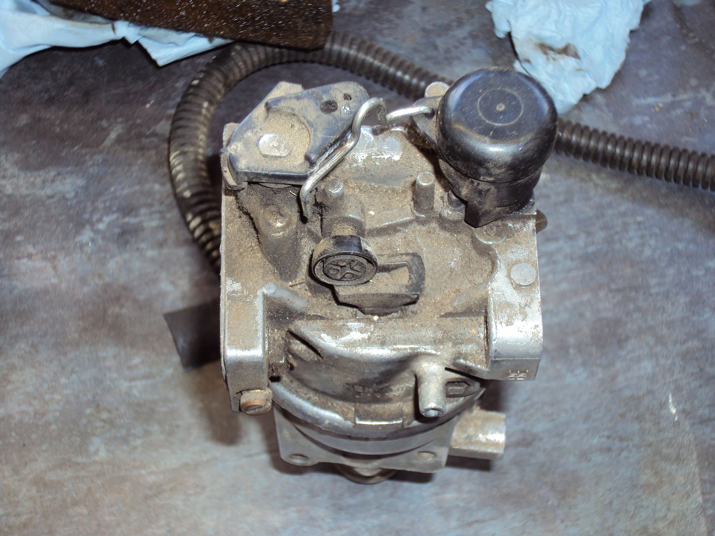
After:
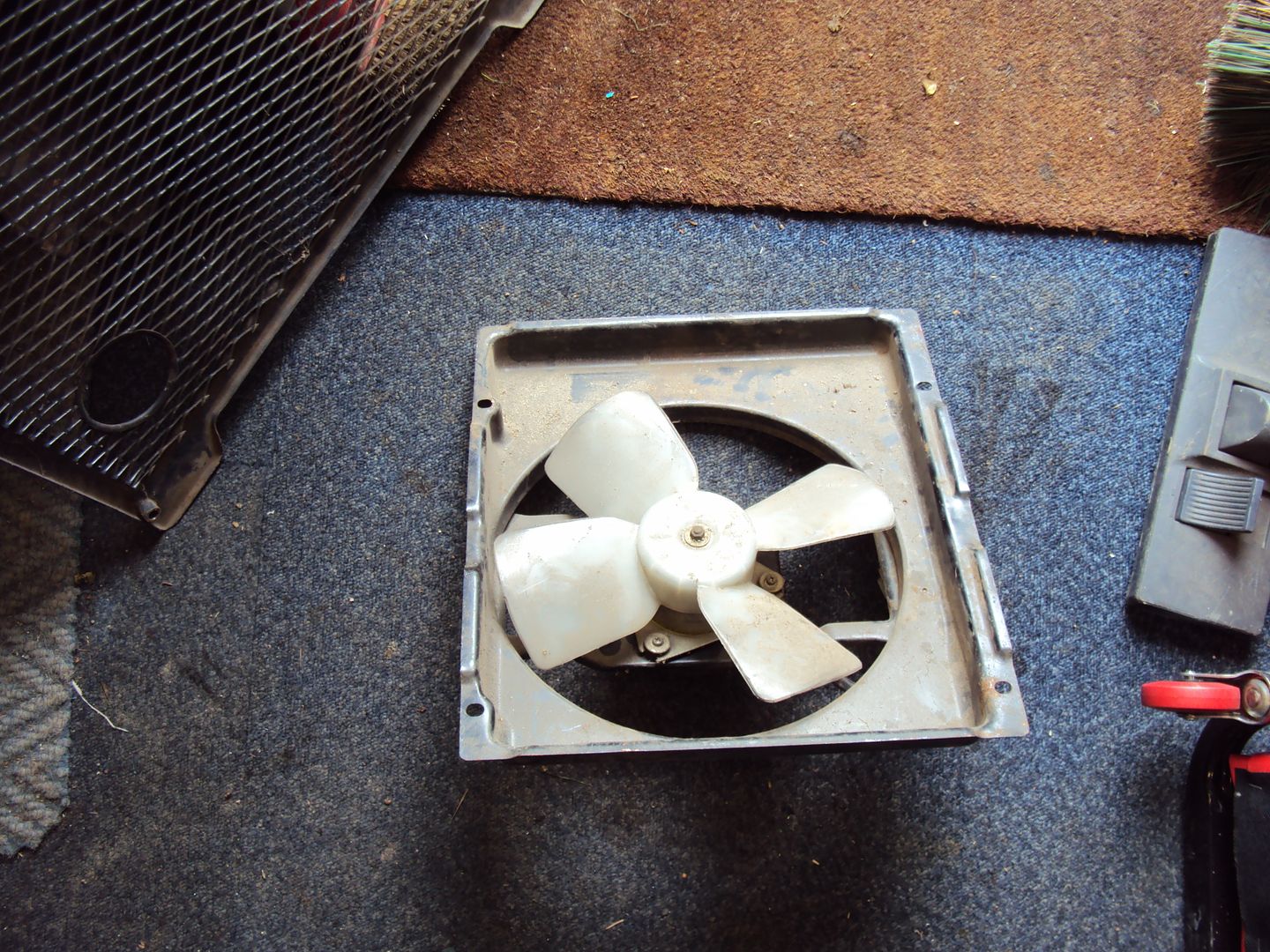
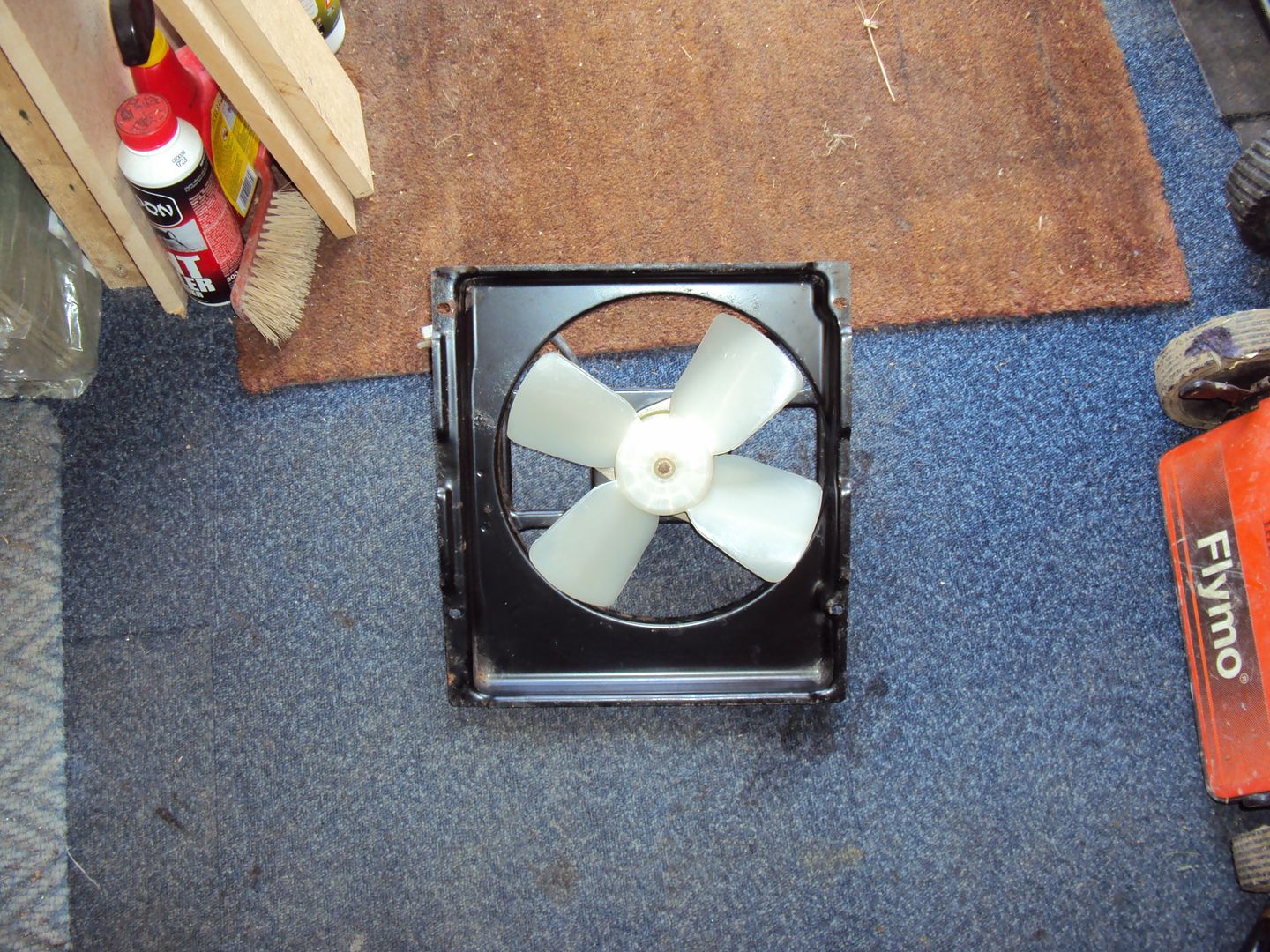
Cooling fan
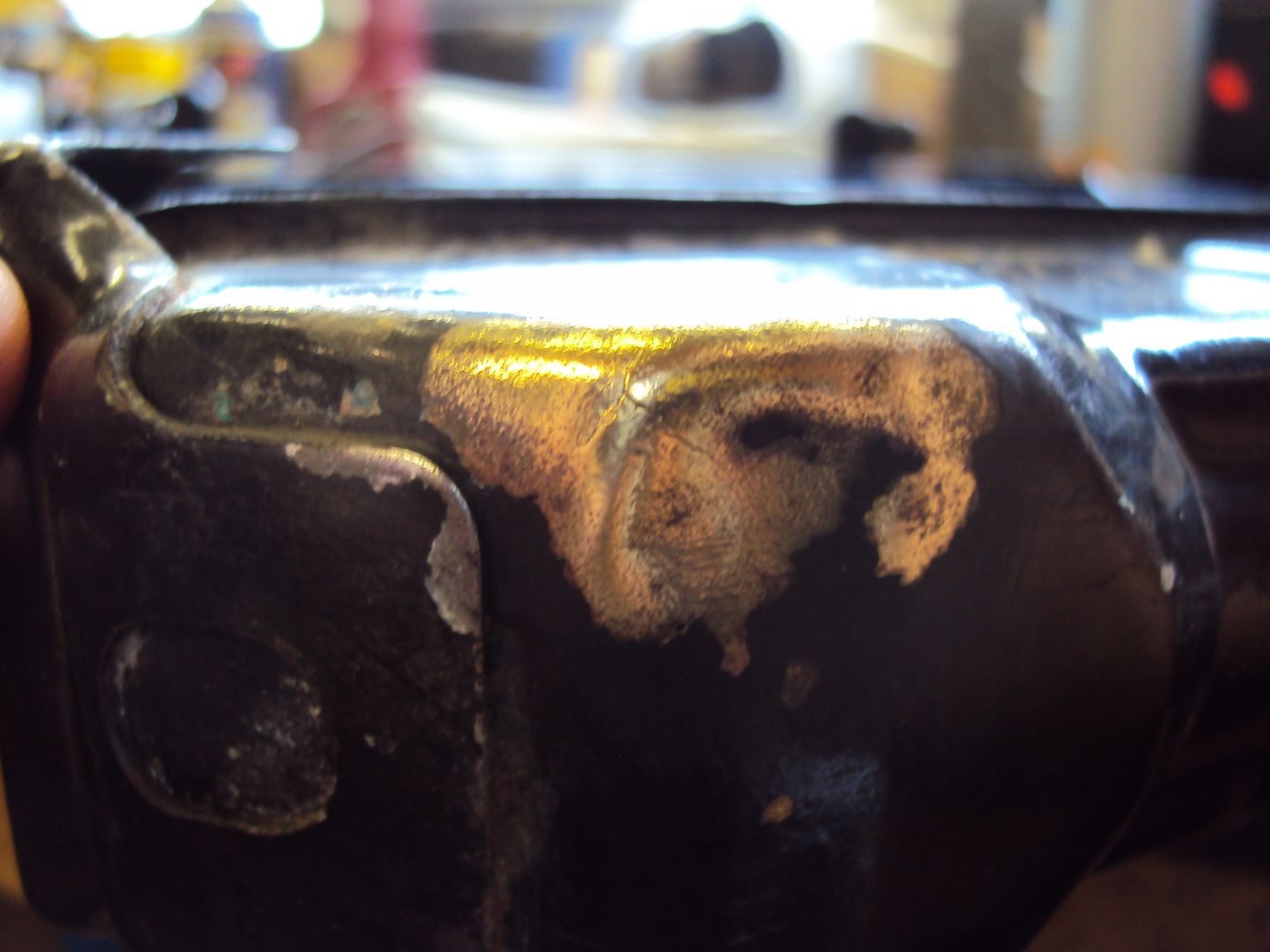
And straightened out some of the bent bodywork
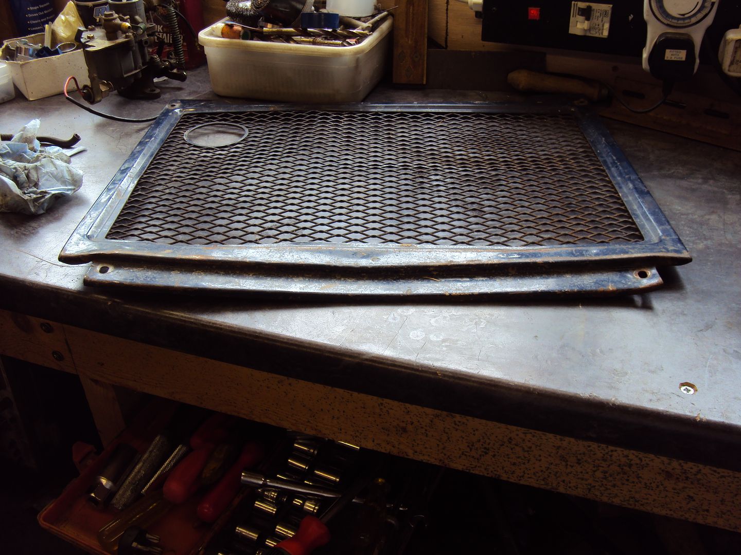
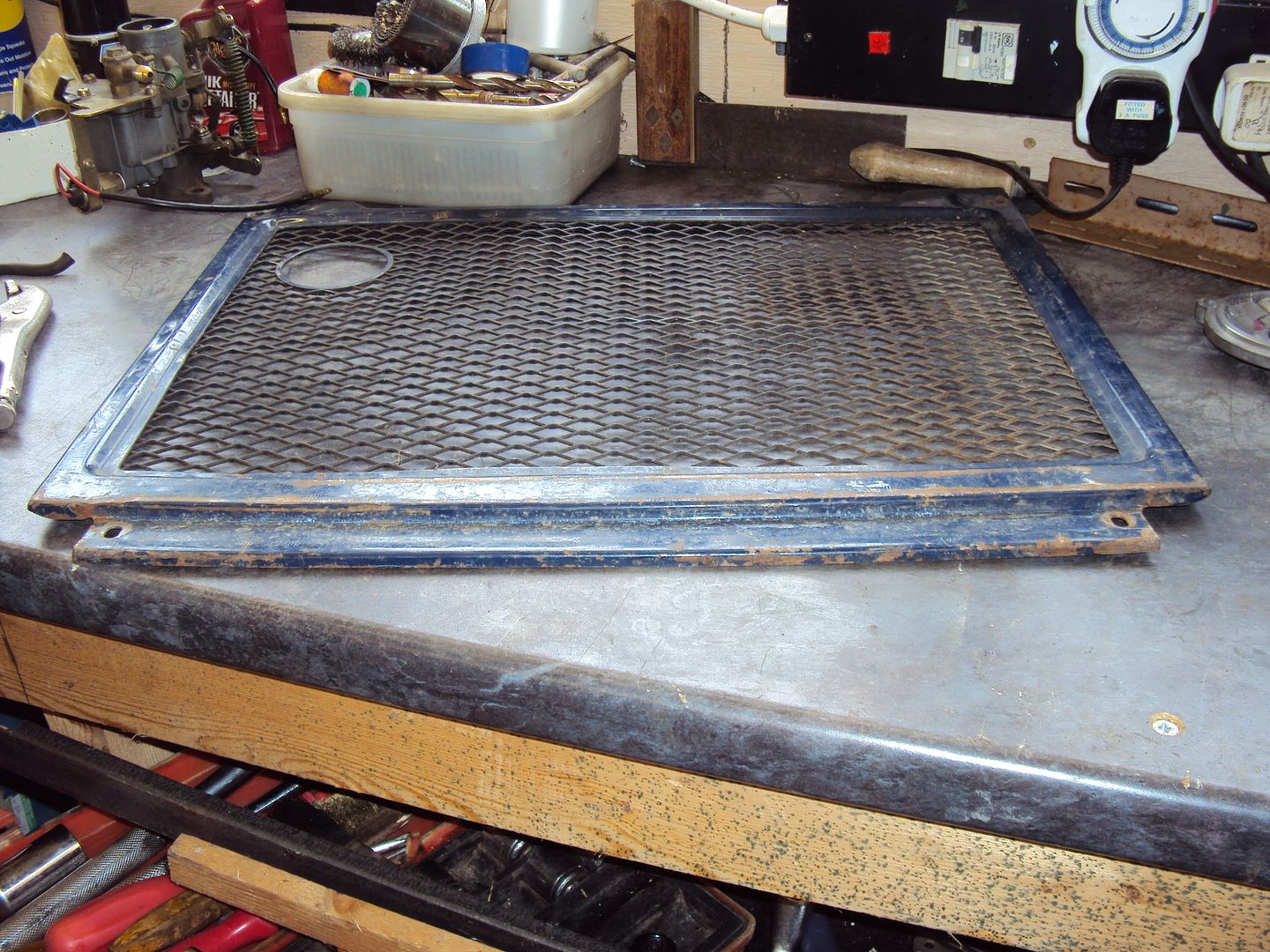
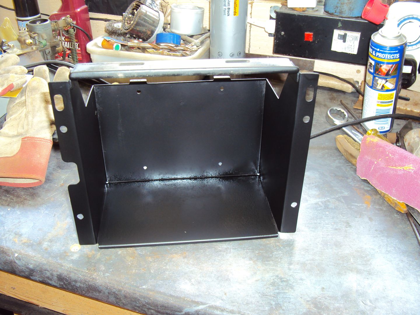
Used the Edd China restoration method on the battery box, if it's rusty, give it a sand and good coat of black satin paint
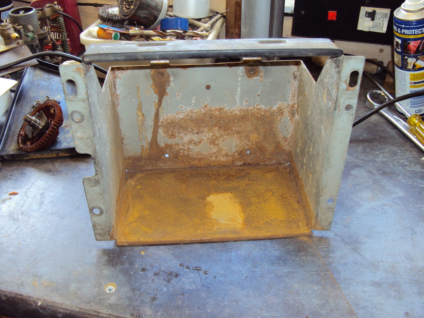
Sanded
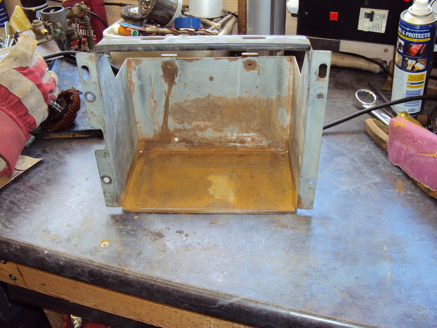
Painted
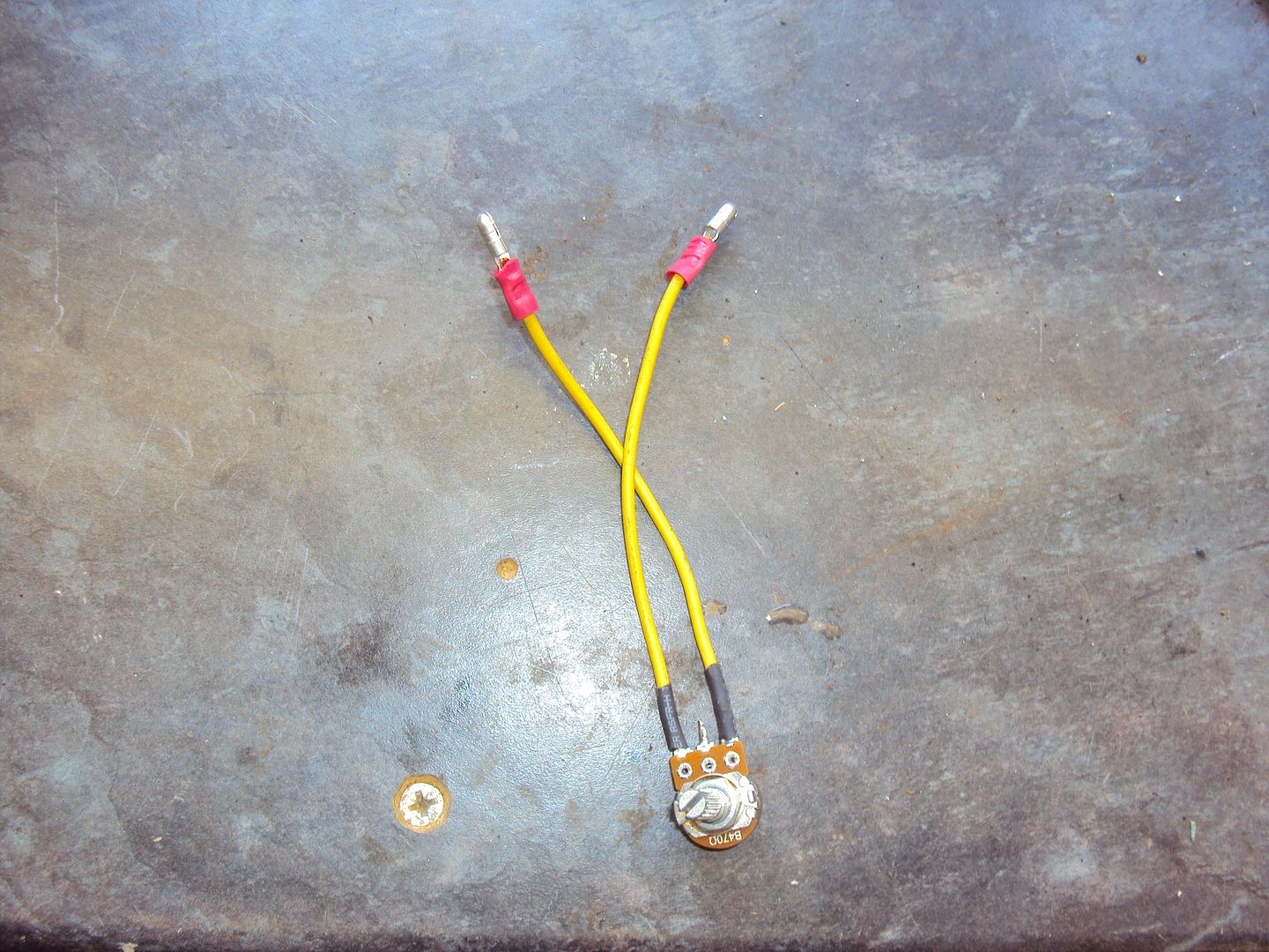
Also replaced the voltage adjuster as it was missing, Honda wanted £60 fortunately the service manual told me it was a 400 ohm pot, so off to ebay and £3 later one replacement voltage adjuster
Got the governor fitted and did a lash up assembly to see if it all worked
After a quick turn over with the plugs removed to check for oil pressure, hooked everything up and filled with water, an this was the result (click pic for video)
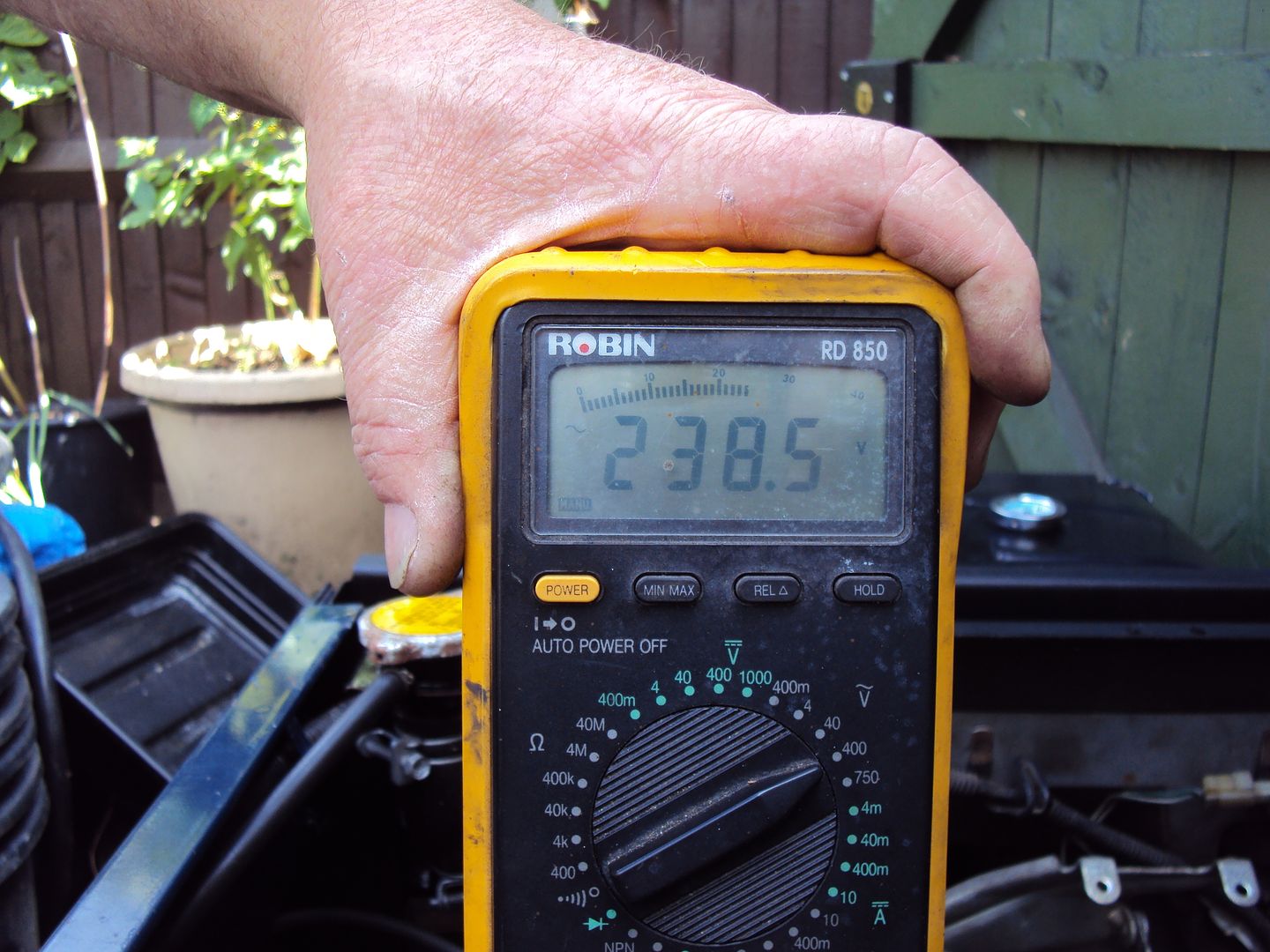
finally got to test the output of the generator, as up until now I hadn't had it running long enough to test it. Both windings of the alternator were putting out 140v, I was expecting 120v (windings are connected in series to make 240v) so now need to check the engine speed and possibly re-wire the voltage adjuster.
While I was waiting for the governor I cleaned up some of the parts
carburettor before:
After:
Cooling fan
And straightened out some of the bent bodywork
Used the Edd China restoration method on the battery box, if it's rusty, give it a sand and good coat of black satin paint
Sanded
Painted
Also replaced the voltage adjuster as it was missing, Honda wanted £60
fortunately the service manual told me it was a 400 ohm pot, so off to ebay and £3 later one replacement voltage adjusterGot the governor fitted and did a lash up assembly to see if it all worked
After a quick turn over with the plugs removed to check for oil pressure, hooked everything up and filled with water, an this was the result
(click pic for video)finally got to test the output of the generator, as up until now I hadn't had it running long enough to test it. Both windings of the alternator were putting out 140v, I was expecting 120v (windings are connected in series to make 240v) so now need to check the engine speed and possibly re-wire the voltage adjuster.
LordLoveLength said:
You've definitely wired the pot wrong - the adjustable output is the middle pin. You've got it wired across the fixed resistor - the bit that never changes!
Also, you might want to look at a better pot than that. It isn't really protected against moisture or dirt ingress. Have look for a wire wound type -they will be better sealed and not much more expensive.
It's connected as per Honda's wiring diagram, the photo doesn't show that there is a link between the wiper and one end of the fixed resistor.Also, you might want to look at a better pot than that. It isn't really protected against moisture or dirt ingress. Have look for a wire wound type -they will be better sealed and not much more expensive.
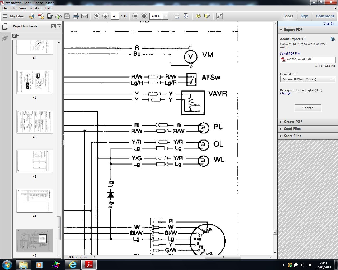
Hopefully dirt shouldn't be a problem as the control panel is sealed.
I had noticed one mistake when I tested the alternator output, I forgot to plug the control panel into the alternator so the adjuster wasn't connected which is probably why the O/P was a bit high.
Tomorrow I'm going to assemble more of the case so I can do a load test.
LordLoveLength said:
Ah! Couldn't see that from the photo!
I just can't believe Honda want £60. I'm in the wrong game.
Yep I couldn't believe the prices either! I need to get replacement lenses for the warning lights, however they can only be bought complete with the lamp holder which are £29 each! Been looking at panel mounting LED's, just need to find one to fit a 16mm hole as most are 10/12mm. I just can't believe Honda want £60. I'm in the wrong game.
Edited by Blue32 on Saturday 7th June 22:00

keo said:
Spark plugs they run on gas. Anyway sorry for the hi jack OP
No problem they look like fun to work on. Don't think I could fit one in the garden shed to play with though
Load test passed and voltage adjuster working
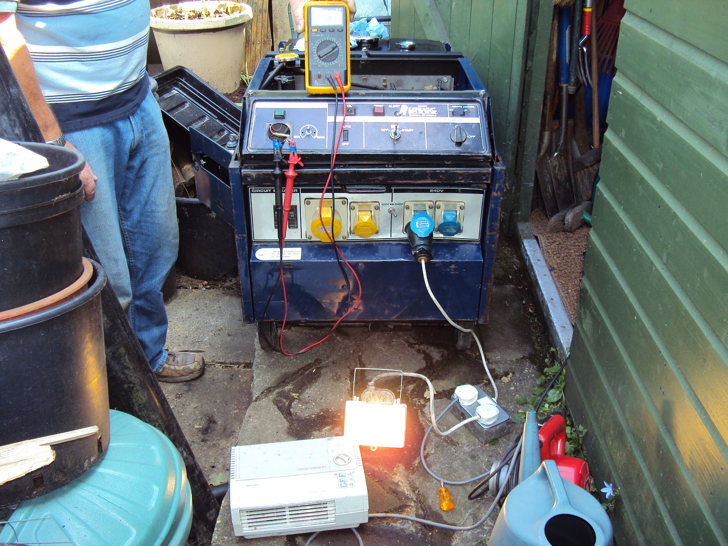
Loaded up with 2x 2000W fan heaters
Running with 2000w fan heater + 120w flood light
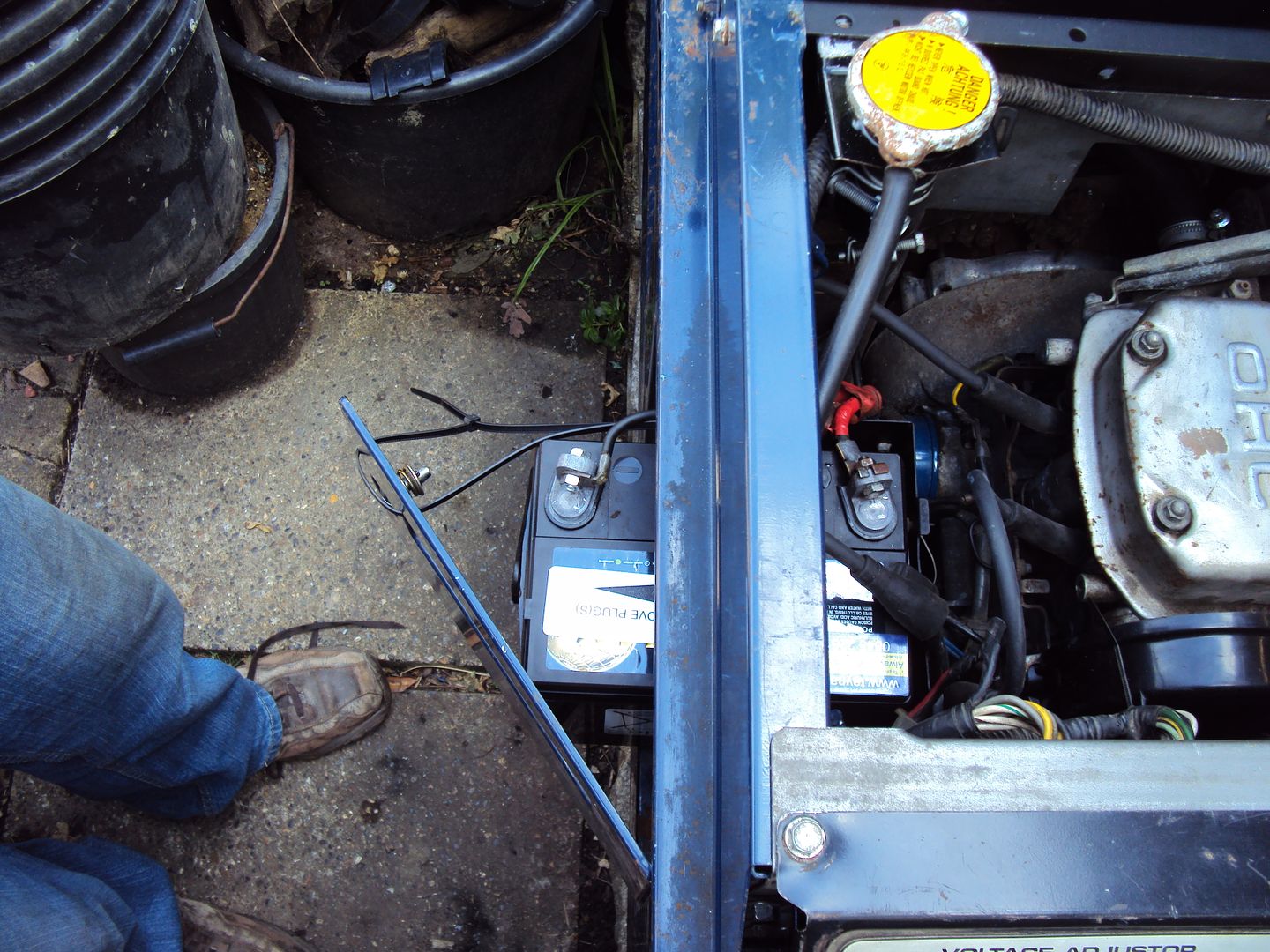
I need to extend the battery leads as the + lead wouldn't reach the terminal, so had to reposition the battery and do a temp lash up with some zip ties to the battery in place so the lead would reach.
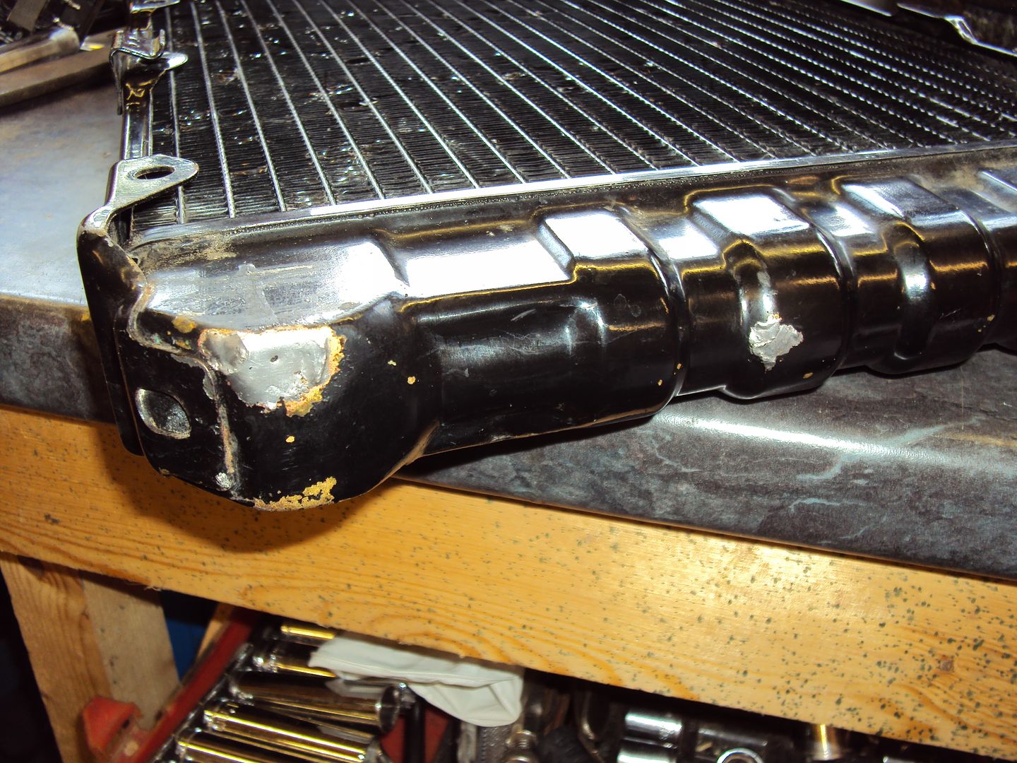
During the test we found a small leak in the radiator end tank, so either need to put some radweld in, or find someone to braze it up.
Also need to source a replacement volt meter as it is missing and buy a proper key as my home made key is starting to bend a bit.
I have made a new cable to go from the battery to the starter motor, the new cable is 10-15cm longer so it can reach the battery terminal.
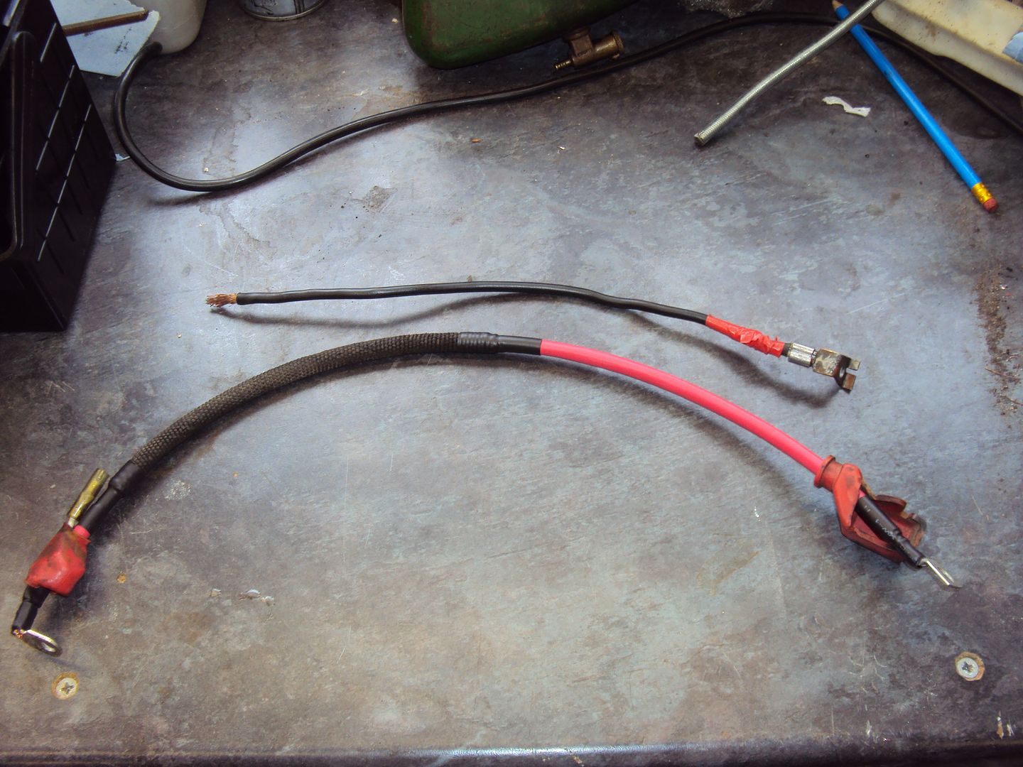
The original volt meter was analogue, I decided to replace it with a digital meter as it would be easier to monitor the voltage, the meter also displays the current being drawn.
Meter cut into front panel, just need to make a cover to go over the remainder of the hole for the old meter.
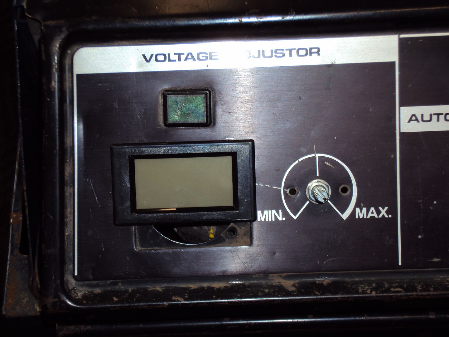
The original volt meter was analogue, I decided to replace it with a digital meter as it would be easier to monitor the voltage, the meter also displays the current being drawn.
Meter cut into front panel, just need to make a cover to go over the remainder of the hole for the old meter.
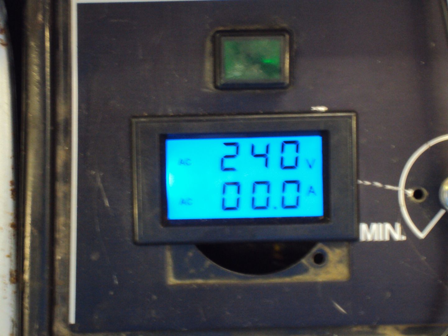
Digital voltage/current meter now wired up and working
I have now got everything re-assembled, just need 10 bolts replaced as they were stripped.
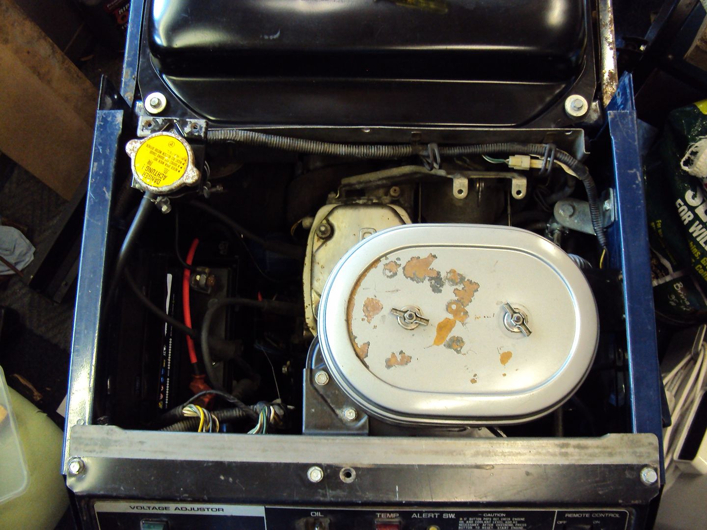
Air filter reattached
Now for the real geaky bit

I wanted to check the output frequency, I started by looking at the incoming mains to the man cave (AKA garden shed ) with an oscilloscope
Unfortunately I don’t have a nice digital scope which works everything out, so have to do it the old way.
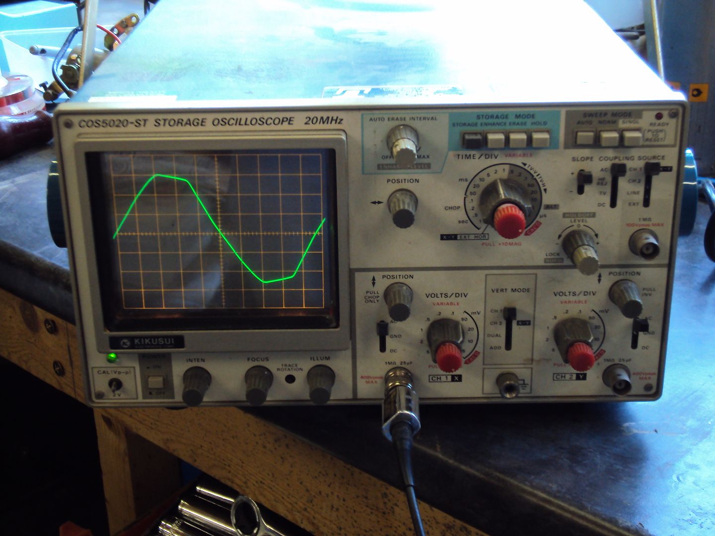
To calculate the frequency I use the formula F= 1/T where T is the time base of the oscilloscope. To measure the frequency the number of divisions for 1 cycle are counted and are used to multiply the time base setting.
For the incoming mains* the time base was set at 2ms, one cycle was 9.8 divisions which gives 19.6ms (9.8*2ms) giving a frequency of 51.02Hz. Guess I need to get the oscilloscope calibrated…
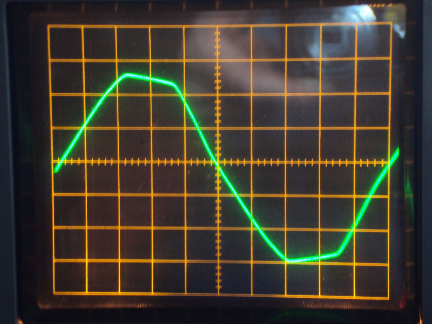
Frequency = 8.4*2 =16.8ms = 59.52Hz
The generator can be set for 50Hz or 60Hz by moving a spring between 2 positions on the governor, so it looks like I put the spring in the wrong position during reassembly.
With the spring moved to the lower position on the governor arm.
Getting there 54.34Hz
Final adjustments are made using a screw which alters the tension on the governor spring, so after a bit of adjustment:

A reasonably stable 50Hz
Not bad for a mechanical control.
I have now got everything re-assembled, just need 10 bolts replaced as they were stripped.
Air filter reattached
Now for the real geaky bit
I wanted to check the output frequency, I started by looking at the incoming mains to the man cave (AKA garden shed
) with an oscilloscope Unfortunately I don’t have a nice digital scope which works everything out, so have to do it the old way.
To calculate the frequency I use the formula F= 1/T where T is the time base of the oscilloscope. To measure the frequency the number of divisions for 1 cycle are counted and are used to multiply the time base setting.
For the incoming mains* the time base was set at 2ms, one cycle was 9.8 divisions which gives 19.6ms (9.8*2ms) giving a frequency of 51.02Hz. Guess I need to get the oscilloscope calibrated…
- NOTE I did NOT connect the oscilloscope directly to the mains, the measurements were made via a transformer to drop the voltage to a safe level.
Frequency = 8.4*2 =16.8ms = 59.52Hz
The generator can be set for 50Hz or 60Hz by moving a spring between 2 positions on the governor, so it looks like I put the spring in the wrong position during reassembly.
With the spring moved to the lower position on the governor arm.
Getting there 54.34Hz
Final adjustments are made using a screw which alters the tension on the governor spring, so after a bit of adjustment:
A reasonably stable 50Hz
Not bad for a mechanical control.
MatrixXXx said:
Just set your multimeter to Hz?
You Normally set the mechanical governour to 2.5 Hz higher than your nominal frequency , then when you load up the generator it will be at 50 Hz at full load (Droop)
My multimeter doesn't do frequency, I might upgrade it to a nice Fluke one day.You Normally set the mechanical governour to 2.5 Hz higher than your nominal frequency , then when you load up the generator it will be at 50 Hz at full load (Droop)
I haven't done a load test since setting the governor, when I do I'll give your suggestion a try if the frequency drops under load
The service manual just says to set the engine speed to 3,200rpm (no load), I don't have a tachometer so just set it up based on the O/P frequency.
If I can build a suitable inductive pickup to work from the spark (magneto fires once for each revolution)I might be able to build a tachometer using a Arduino board to set it up better.
netherfield said:
wish I'd found that, I got one from ebay and it cost more.Jer_1974 said:
Nice thread. Would be interested in how much profit you made on it.
Thanks Not sure on profit yet, probably won't sell it until winter.I have started building the tachometer, because the generator doesn’t use points I needed to build something that would pick up the spark and convert it into something I could feed into an Adruino.
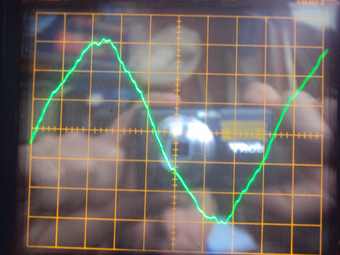
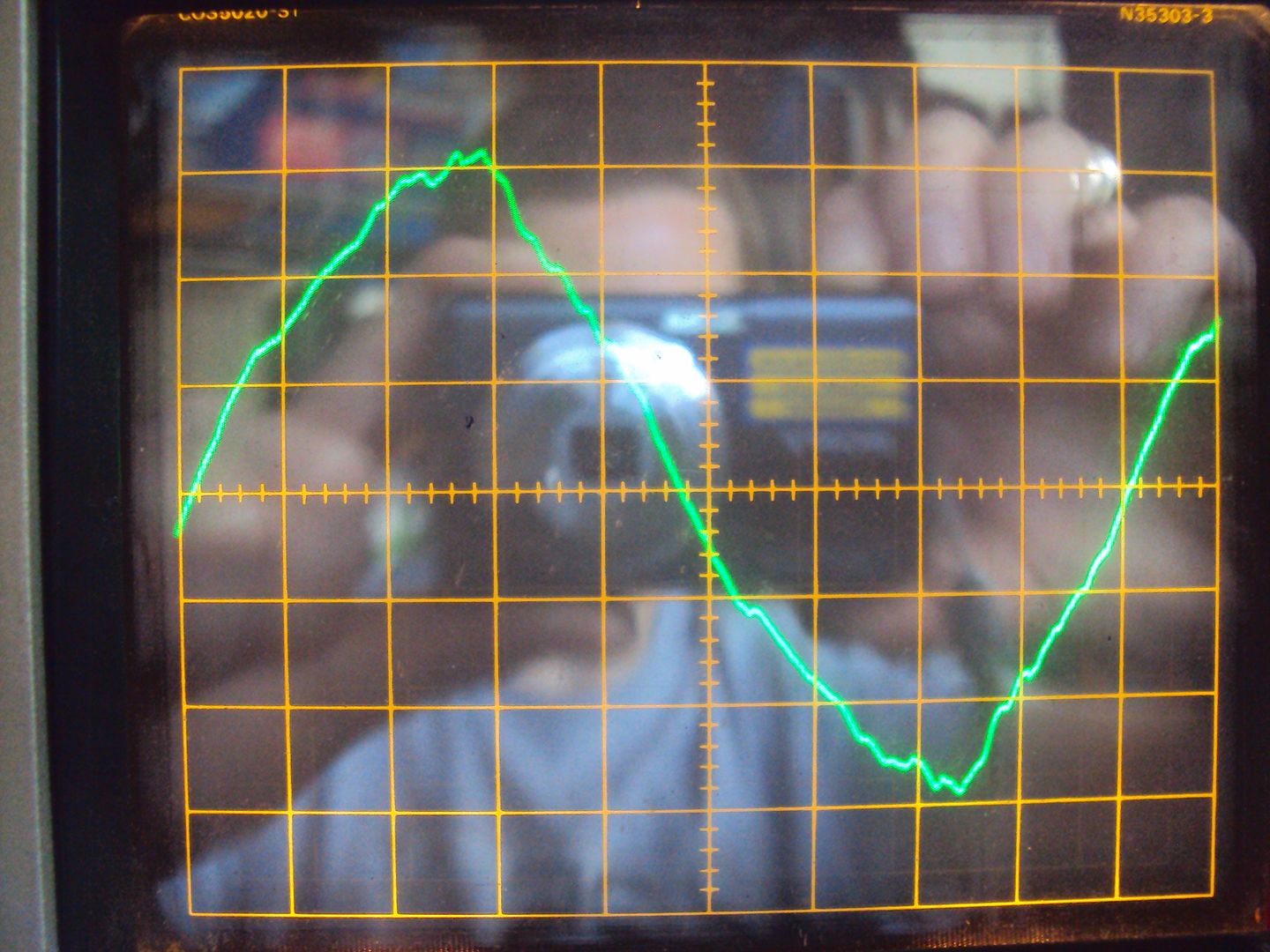
After a bit of searching I found this: http://fly.srk.fer.hr/~wgottwe/e98a034.pdf and built the first part which is based around a 555 timer IC. The circuit uses a few turns of wire around the HT lead to pick up the spark pulse.
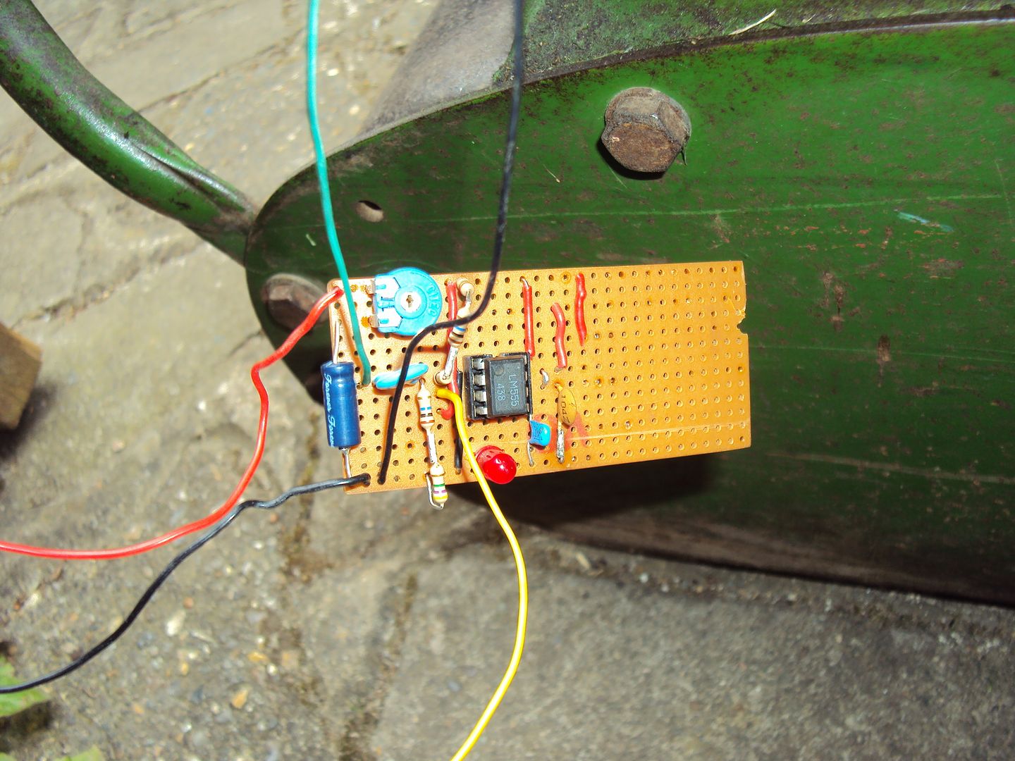
I constructed the circuit on strip board
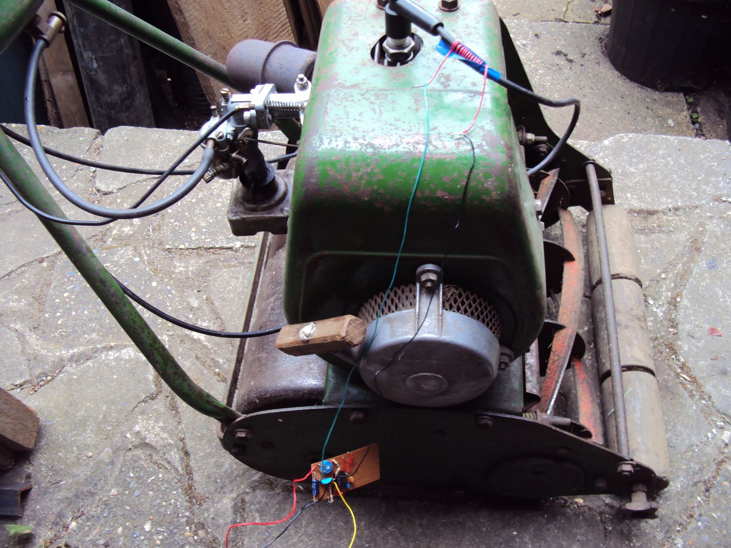
And tested on the lawnmower
Some nice microcontroller compatible pulses
All I need to do now is to write the code on the Adruino to count the pulses and calculate the RPM and display on a screen.
After a bit of searching I found this: http://fly.srk.fer.hr/~wgottwe/e98a034.pdf and built the first part which is based around a 555 timer IC. The circuit uses a few turns of wire around the HT lead to pick up the spark pulse.
I constructed the circuit on strip board
And tested on the lawnmower
Some nice microcontroller compatible pulses
All I need to do now is to write the code on the Adruino to count the pulses and calculate the RPM and display on a screen.
Not having much luck with the DIY tachometer (most likely my rubbish coding) so decided to tackle the radiator as it has a couple of small cracks which are leaking.
When I removed the radiator I noticed there were bits of scale in the water (had flushed it through during the original strip down) so I broke out a birthday present from last year,

http://www.maplin.co.uk/p/handheld-video-optic-ins...
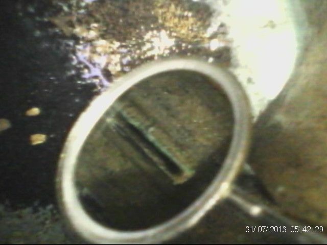
And had a look inside
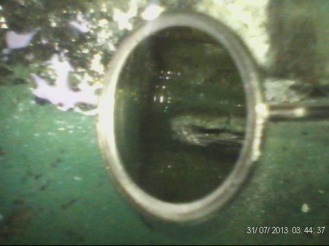
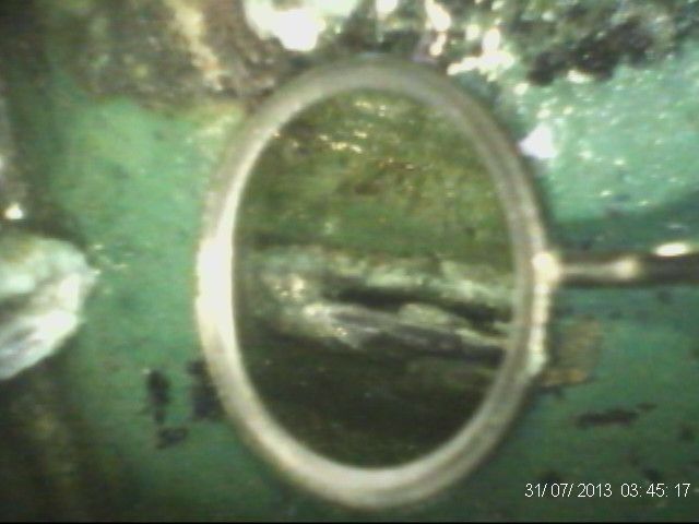
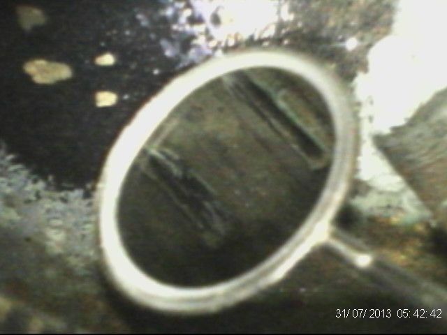
Not looking too good so I decided to try some kettle de-scalier, after a couple of treatments it looked a lot better.
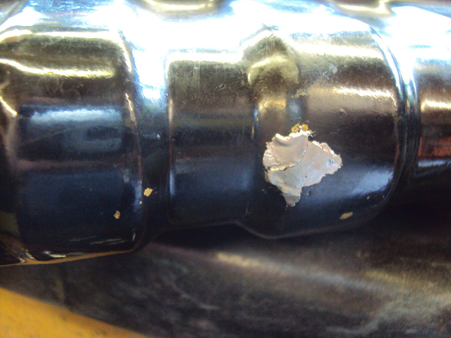
To repair the cracks I borrowed a 200w soldering ion from work (normal soldering ion on left)
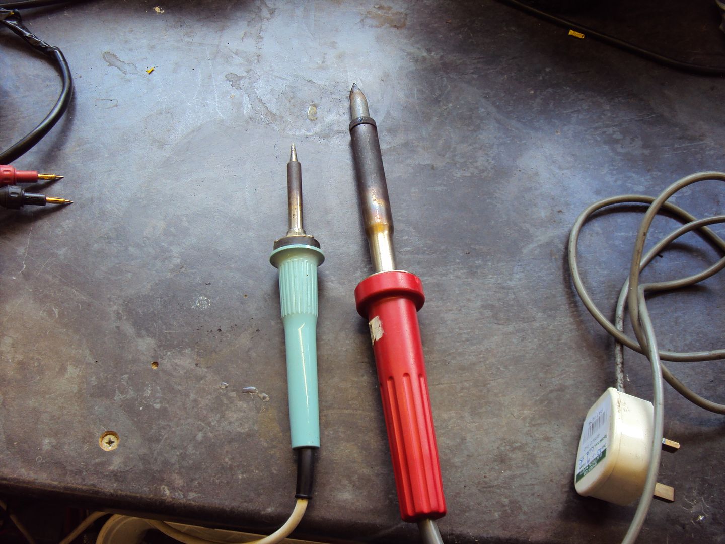
Soldered up the cracks with plumbing solder.
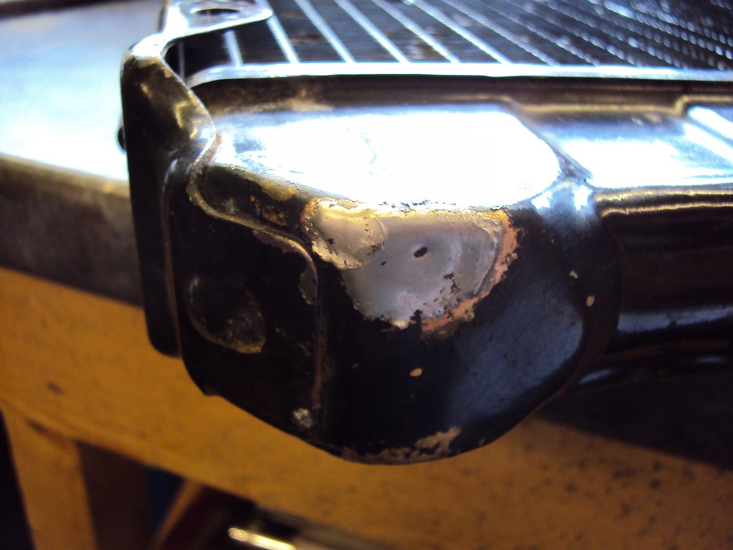
I re-assembled everything and ran it up, and there were no leaks. Have since put some Holts speedflush in the cooling system to clean it up before re-filling with a 50/50 mix of anti freeze.
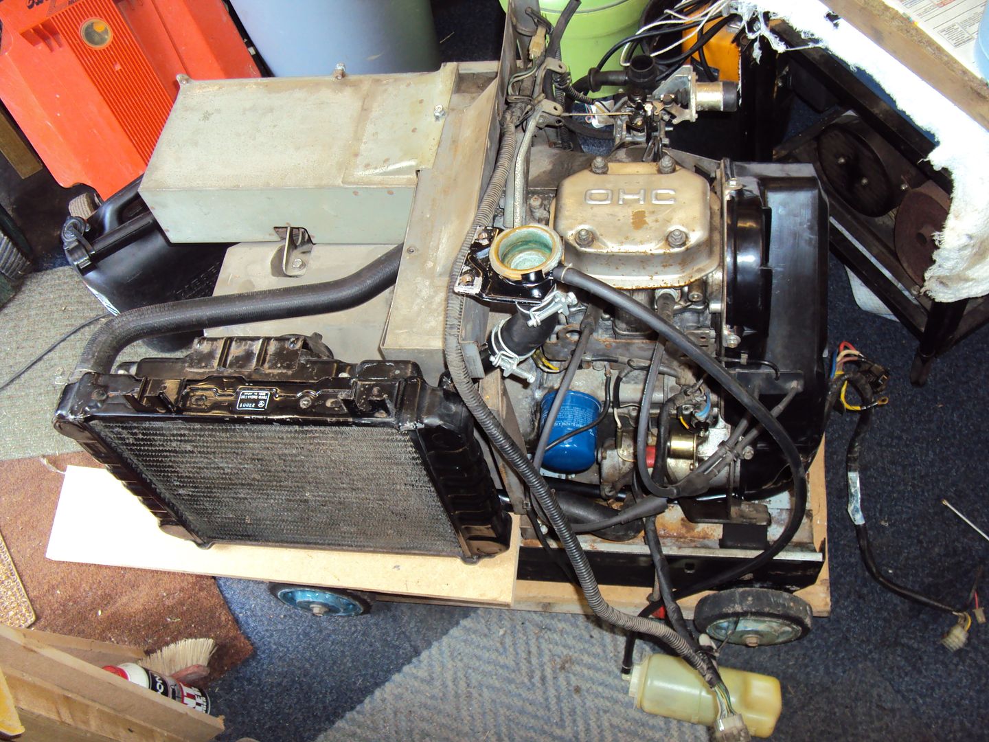
Whilst trawling ebay I found the next project which I picked up yesterday,
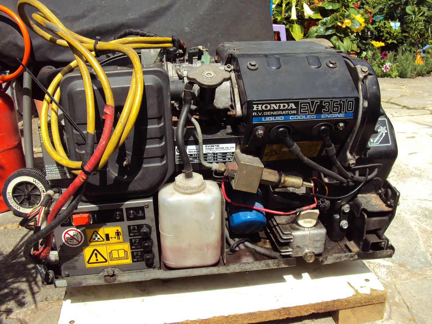
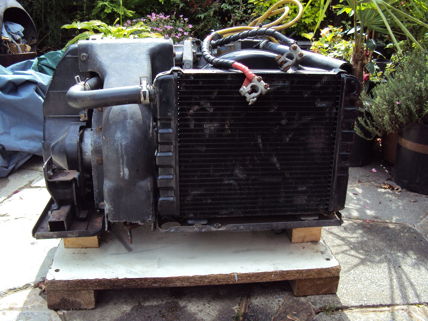
It is essentially the same, as ex5500 except it is for mounting in a motor home so doesn’t have the big case and fuel tank.
The fault with this one is that it will run for a while before cutting out. The seller told me that it has had a new cam belt and head gasket, after a quick inspection I could see new gaskets everywhere, so that’s good.
Hopefully it should be an easy fix, the plan is to check the obvious stuff first like the fuel pump and carburettor, if it’s not these it might be the oil pump again.
) so decided to tackle the radiator as it has a couple of small cracks which are leaking.When I removed the radiator I noticed there were bits of scale in the water (had flushed it through during the original strip down) so I broke out a birthday present from last year,
http://www.maplin.co.uk/p/handheld-video-optic-ins...
And had a look inside
Not looking too good so I decided to try some kettle de-scalier, after a couple of treatments it looked a lot better.
To repair the cracks I borrowed a 200w soldering ion from work (normal soldering ion on left)
Soldered up the cracks with plumbing solder.
I re-assembled everything and ran it up, and there were no leaks. Have since put some Holts speedflush in the cooling system to clean it up before re-filling with a 50/50 mix of anti freeze.
Whilst trawling ebay I found the next project which I picked up yesterday,
It is essentially the same, as ex5500 except it is for mounting in a motor home so doesn’t have the big case and fuel tank.
The fault with this one is that it will run for a while before cutting out. The seller told me that it has had a new cam belt and head gasket, after a quick inspection I could see new gaskets everywhere, so that’s good.
Hopefully it should be an easy fix, the plan is to check the obvious stuff first like the fuel pump and carburettor, if it’s not these it might be the oil pump again.
catfood12 said:
Good work OP, great thread too. I wish I had as much spare time as you..... 
Do we have to buy them from ebay to qualify, and do they have to be broken ?
Thanks, I have only spent an hour or two in the evenings/weekends on these, it's just something to tinker with instead of watching rubbish TV.Do we have to buy them from ebay to qualify, and do they have to be broken ?
They don't have to be broken, but working ones are not much of a challenge
Thought I should update progress,
I started by building a stand for the generator as it needed to be raised up as the exhaust goes through the base and out the bottom.
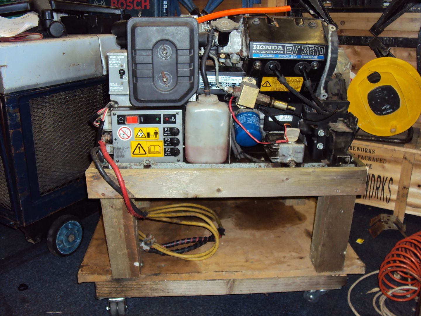
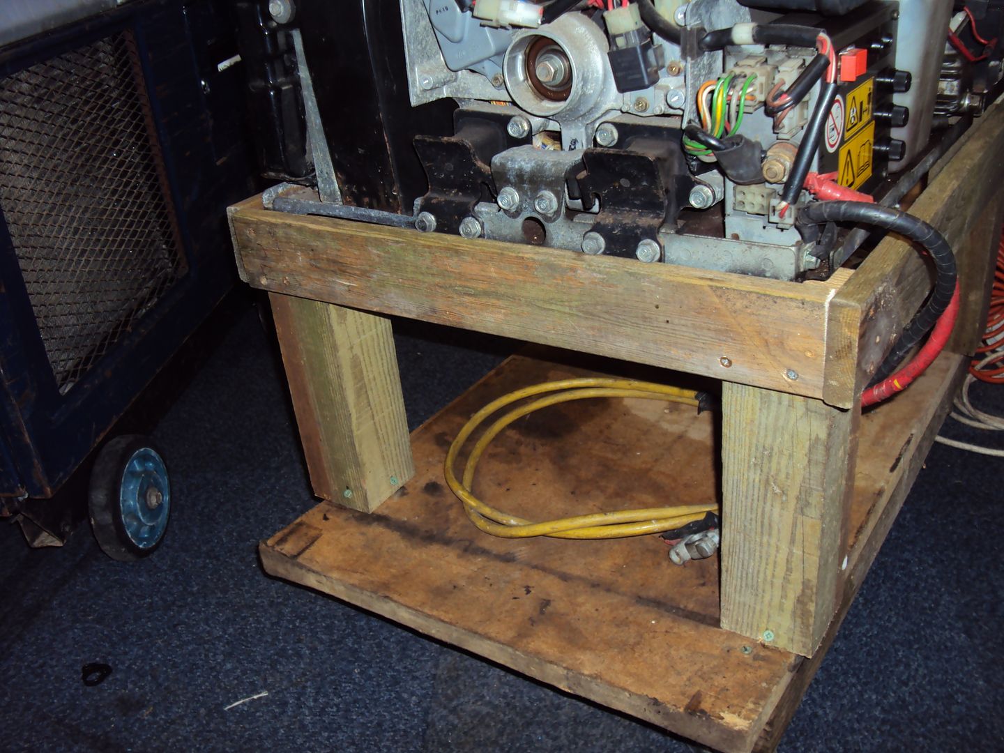
Norm Abram would be proud
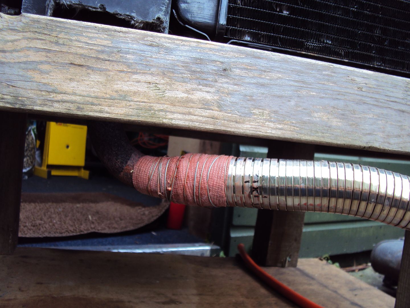
Next I hooked up the exhaust, had to buy some stainless steel flexi tube to connect the silencer to the engine
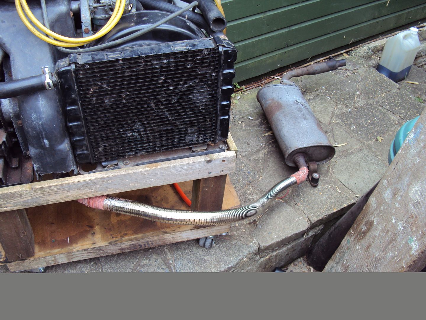
As I don’t have a welder I used some Gun Gum tape to seal the joints.
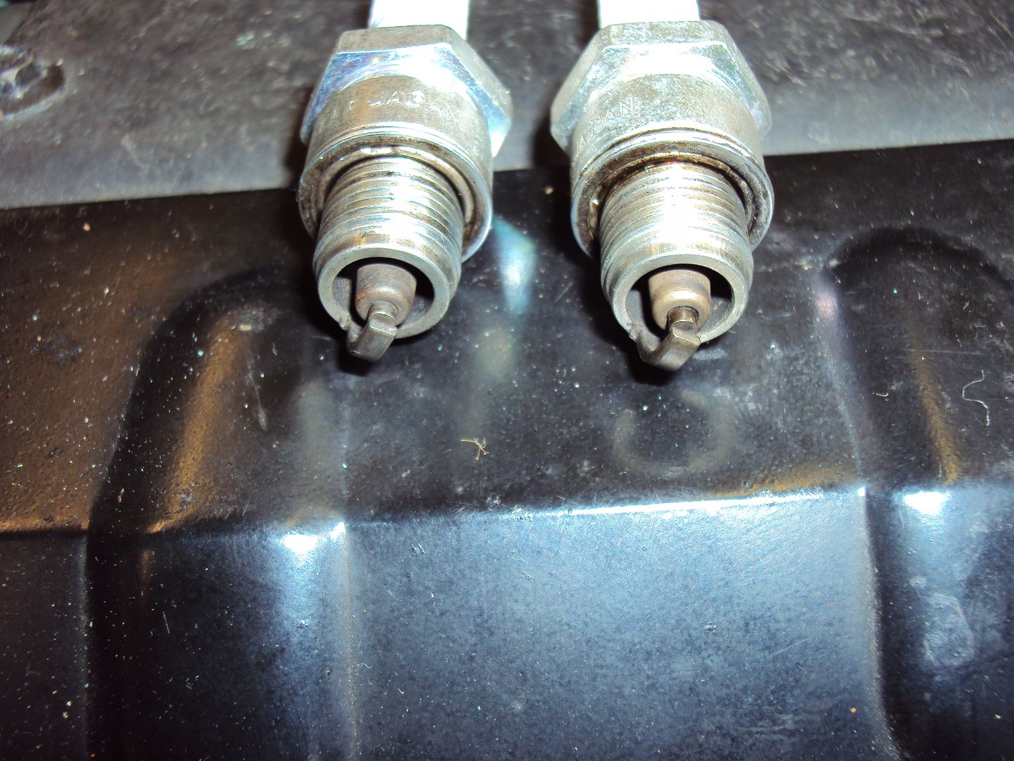
When I tried starting the engine it would run for a second or two with misfiring before cutting out. I took the spark plugs out and cleaned them, which cured the misfire.
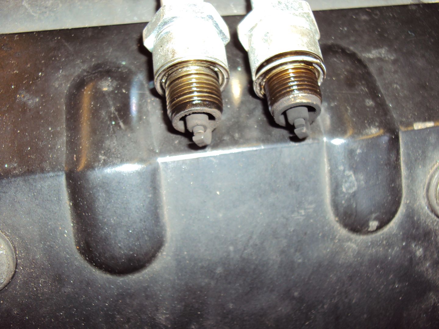
After a quick clean with a wire brush
After some further testing I was able to get the engine to run by hotwiring the fuel pump and disconnection the kill line to the magneto.
With the engine running I could test the alternator, which initially had no output. The next step was to check all the connections and the resistance of the windings.
The alternator has 3 sets of windings, the main windings that make the 240V and 2 sets of sub windings.
The main winding resistance appeared to be ok, was about the same as the EX5500
Main winding resistance
The sub windings had a similar value, not sure if this was right or not but at least they weren’t shot/open circuit.
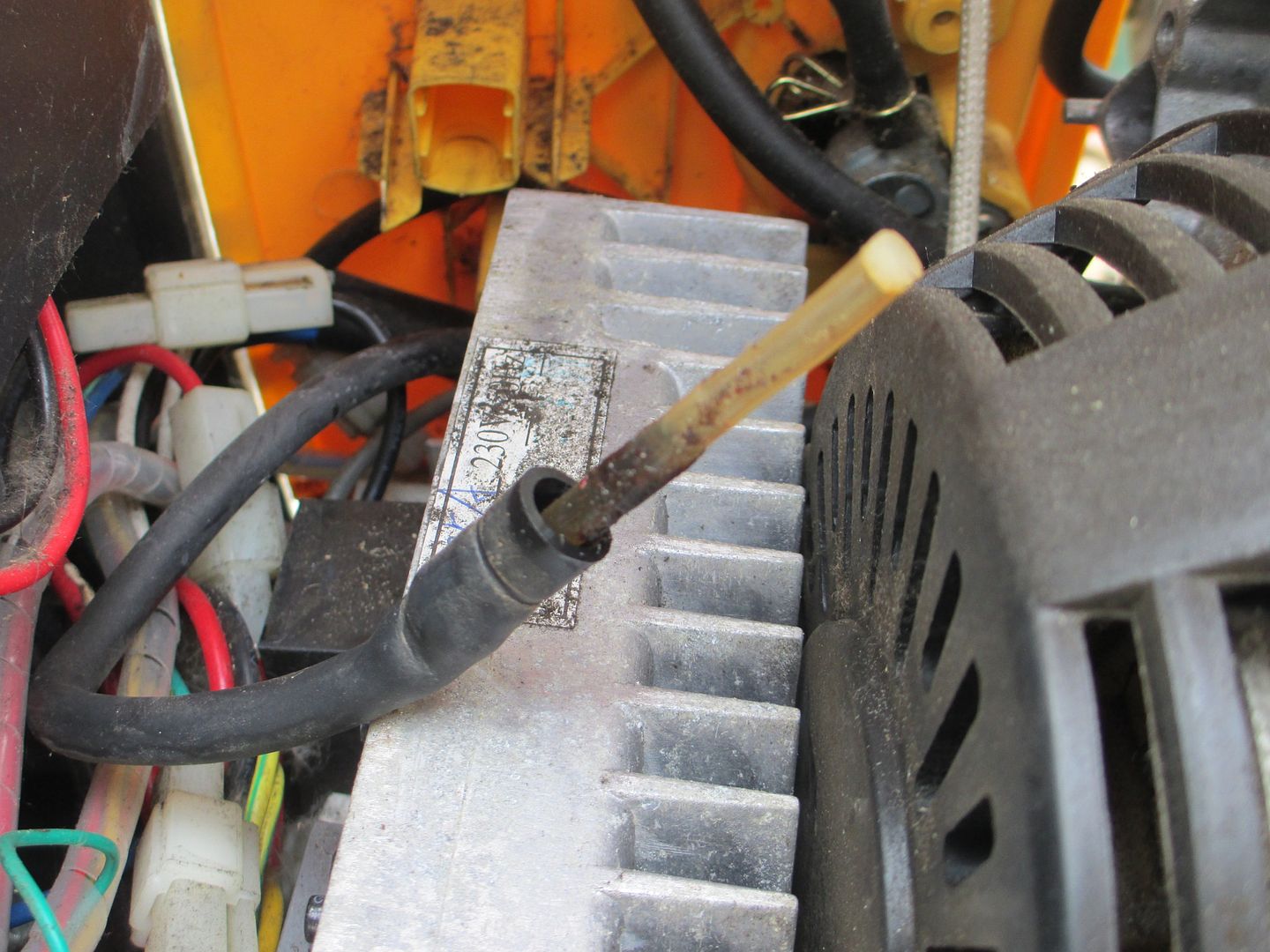
The next thing to check was the “rotor” (bit that spins inside the alternator), during starting a voltage is applied to the rotor to “excite” the main windings.
Once running the AVR (Automatic Voltage Regulator) which is the grey rectangular box with the diamond shaped bit applies a voltage to the rotor to maintain the output voltage. The AVR varies the voltage based on the load.
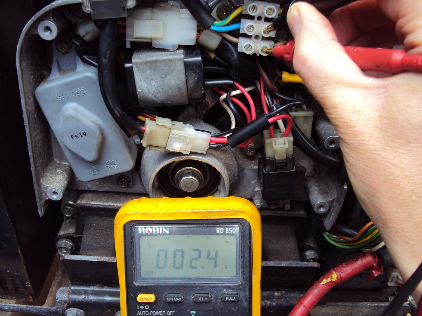
The rotor is connected via carbon brushes which run on brass slip rings, on testing the resistance was very high in the 100’s of ohms when it should be around 60 ohm.
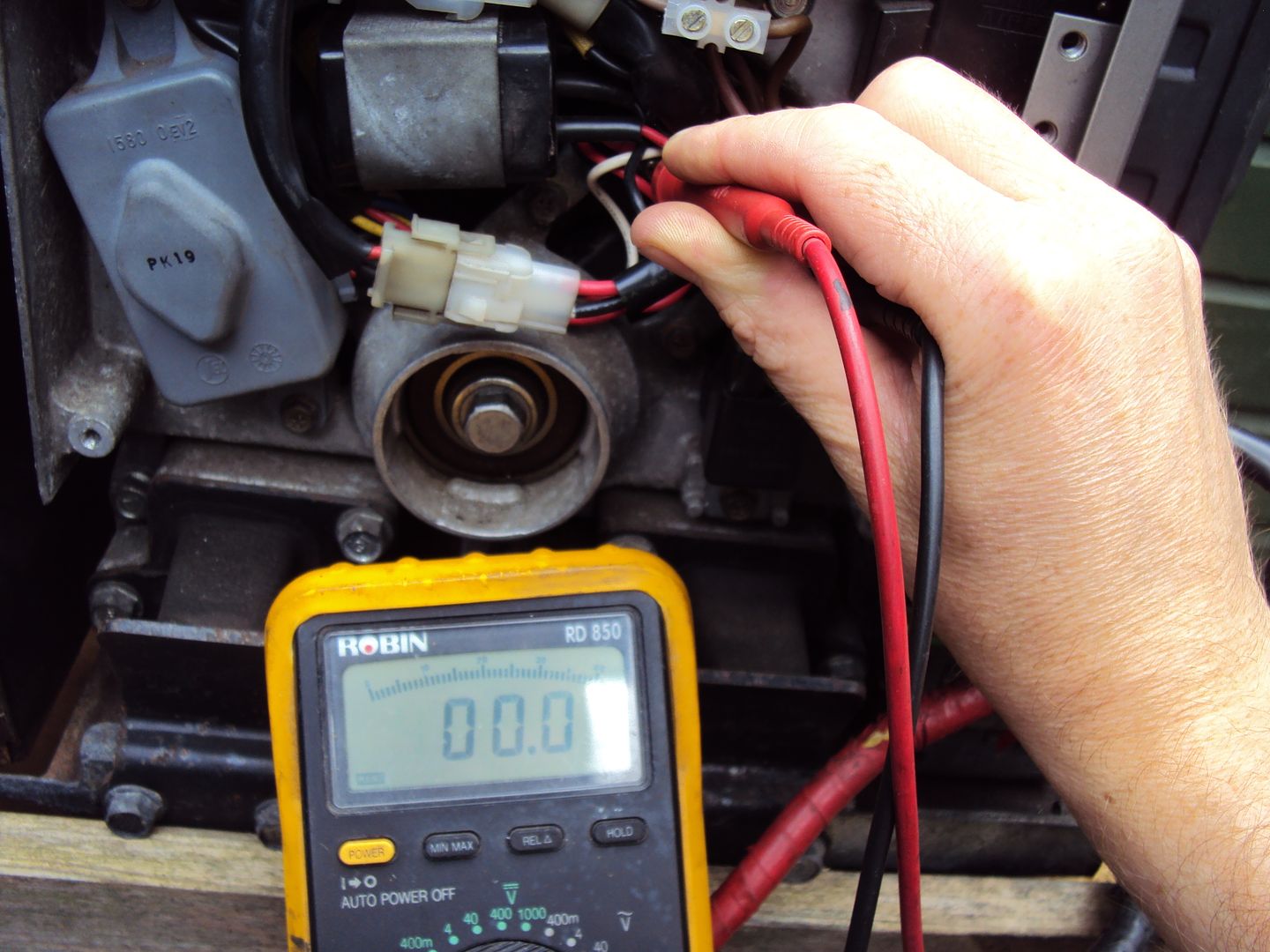
The reading is not 0 ohm, there is a 4 flashing to show it is exceeding the range, couldn’t get the camera to pick it up.
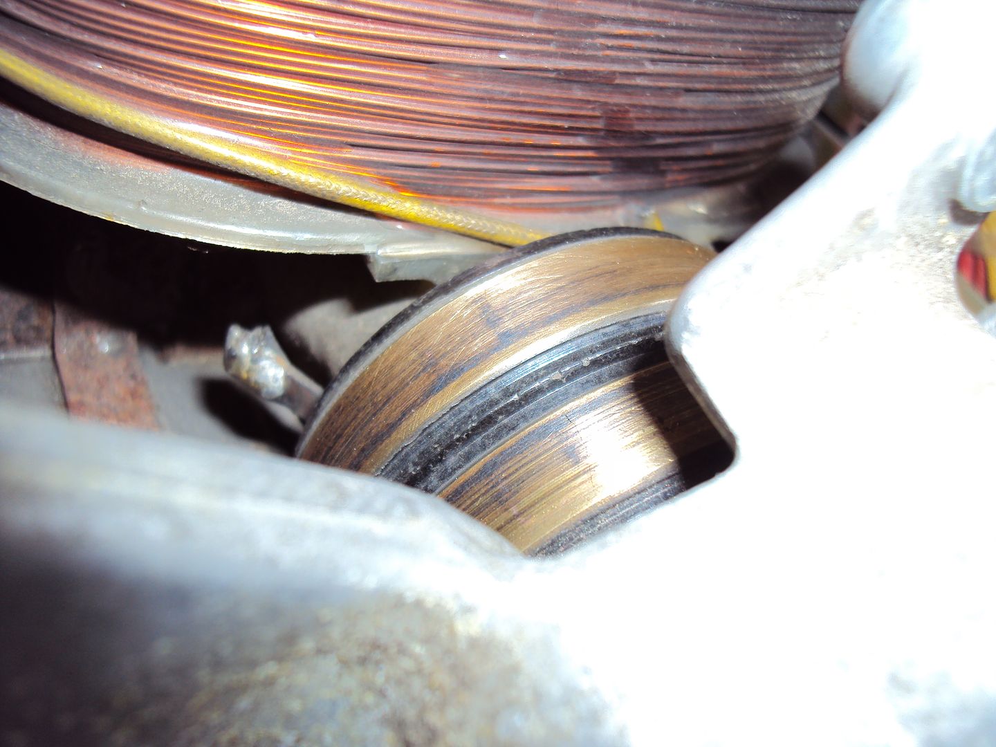
I removed the brushes and inspected the slip rings, which were completely black with dirt (didn’t get a picture). The slip rings were cleaned with a scotch bright cloth.
During
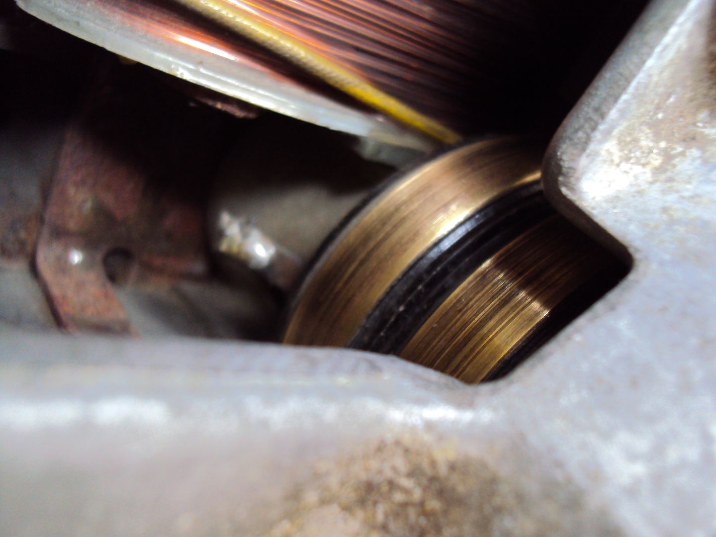
After
Resistance after cleaning
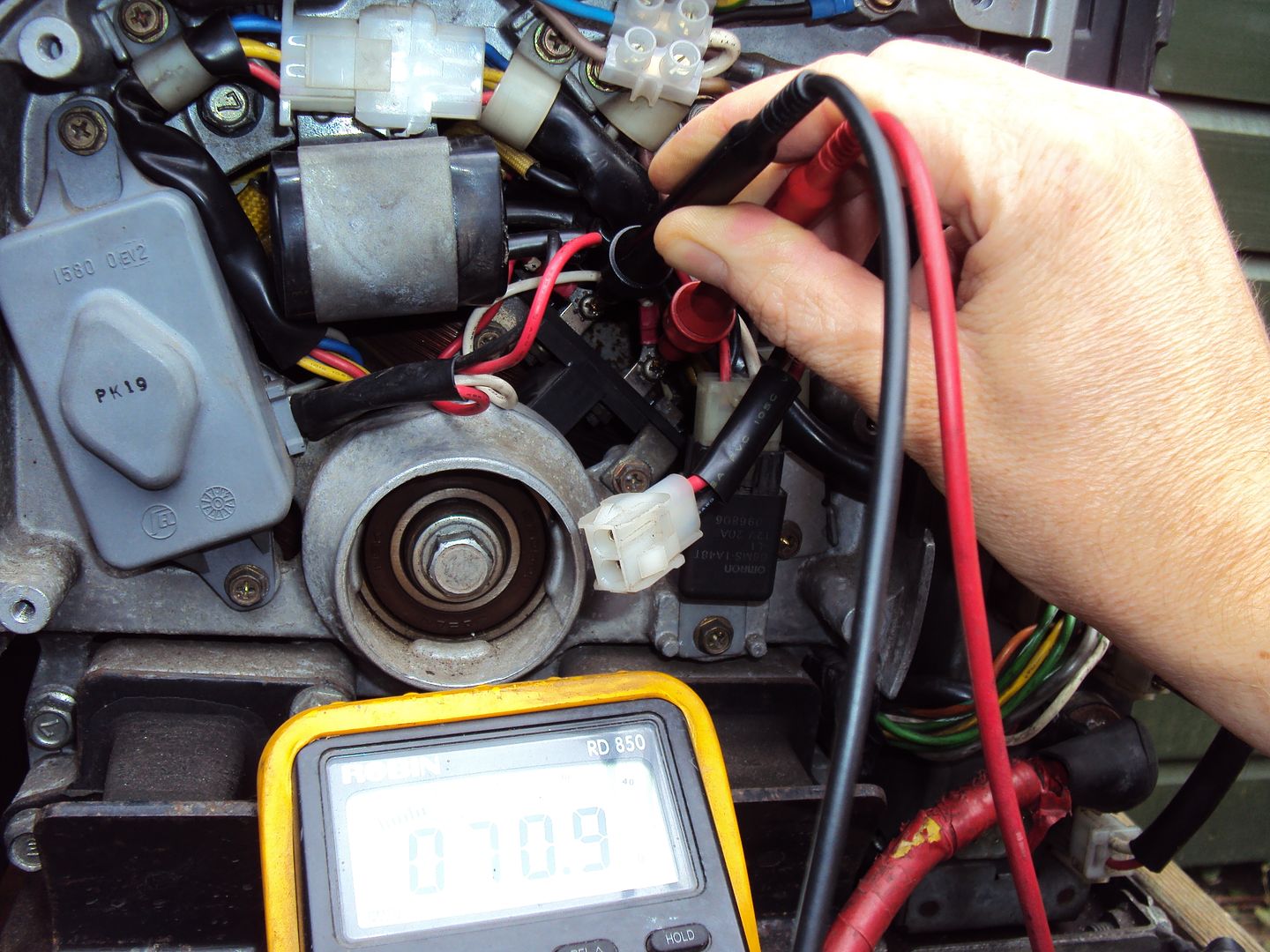
After putting everything back together, I started the engine and it worked
 . It turns out that the control unit was detecting the alternator wasn’t working properly so was shutting the engine down.
 Have now had it running for over an hour powering various things with no problems at all.
If I hadn’t needed to buy the bits for the exhaust, the repair cost would have been £0.00
Next step is to give it a clean as the chassis is a bit oily, once that’s done it will be sold (for a profit hopefully) and keep an eye out foe the next project.
Edited by Blue32 on Tuesday 5th August 17:58
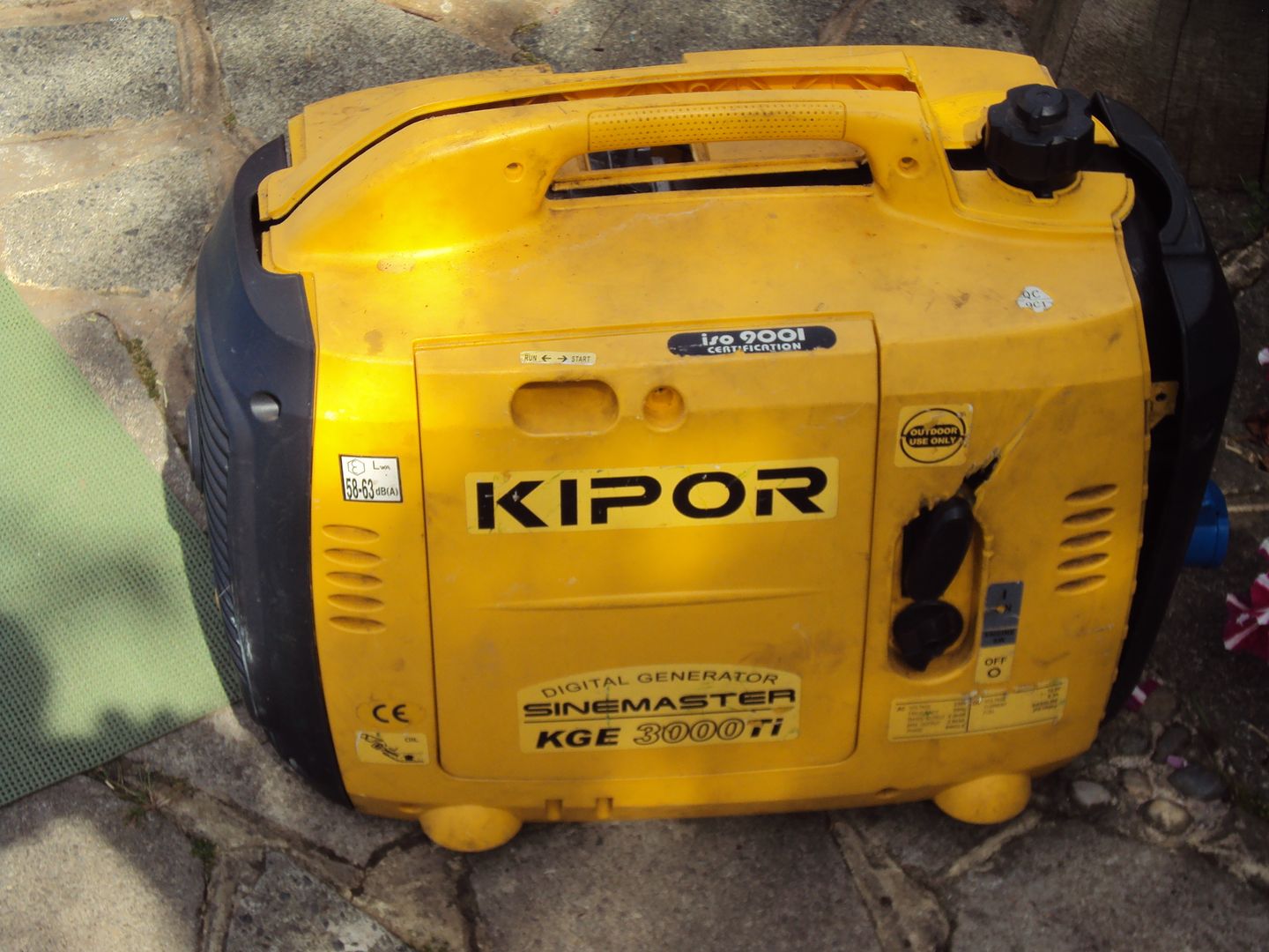
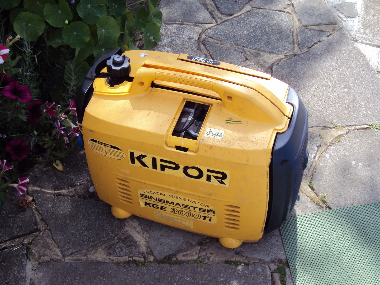
I sold the Honda motorhome generator last week, and used some of the profits to purchase the next project. This time I went for a suitcase type generator (wanted something which doesn’t need 2 people to move)
The fault with this one was that it wouldn’t start, so I started with the obvious things like checking for spark and there is fuel in it as there isn’t much else that can go wrong. The spark was good, however there wasn’t any fuel getting to the carburettor.
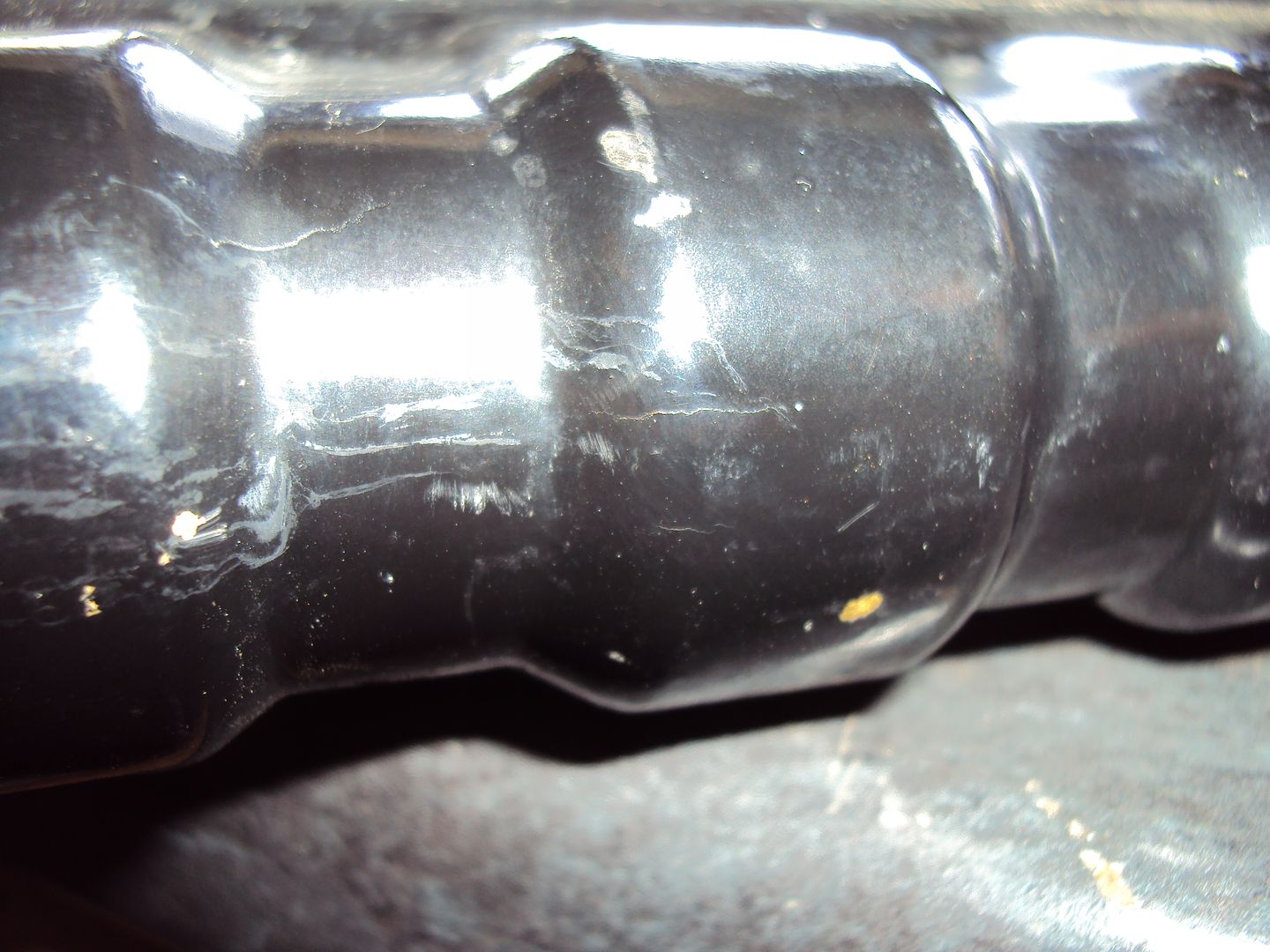
I removed the fuel tank and drained it into a jug, as I thought the in-line fuel filter might be blocked
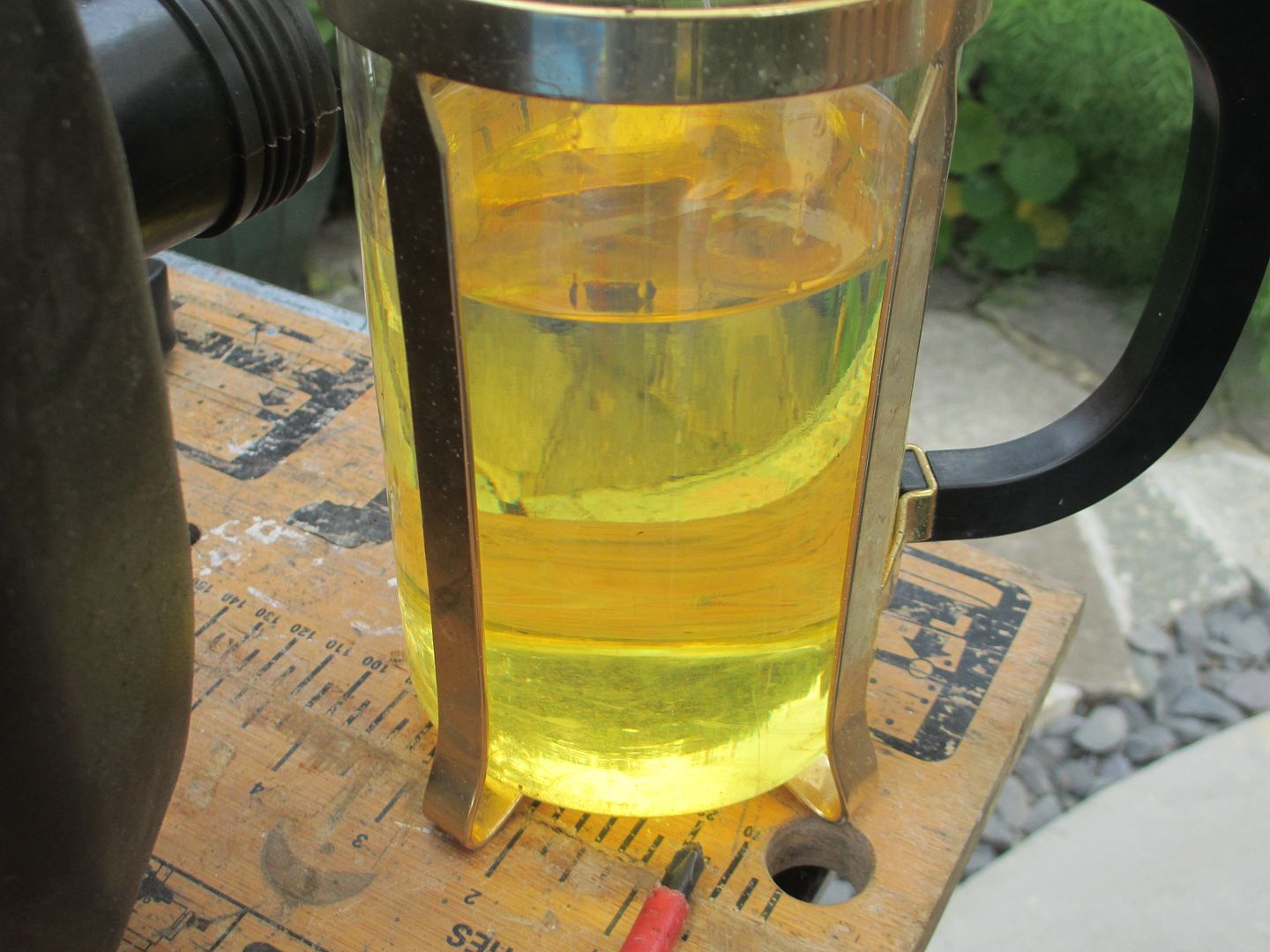
I’m sure petrol shouldn’t be that colour!
The fuel filter is held in the fuel pipe, the filter didn’t look too bad.
I cleaned the filter and put some fresh petrol in the tank
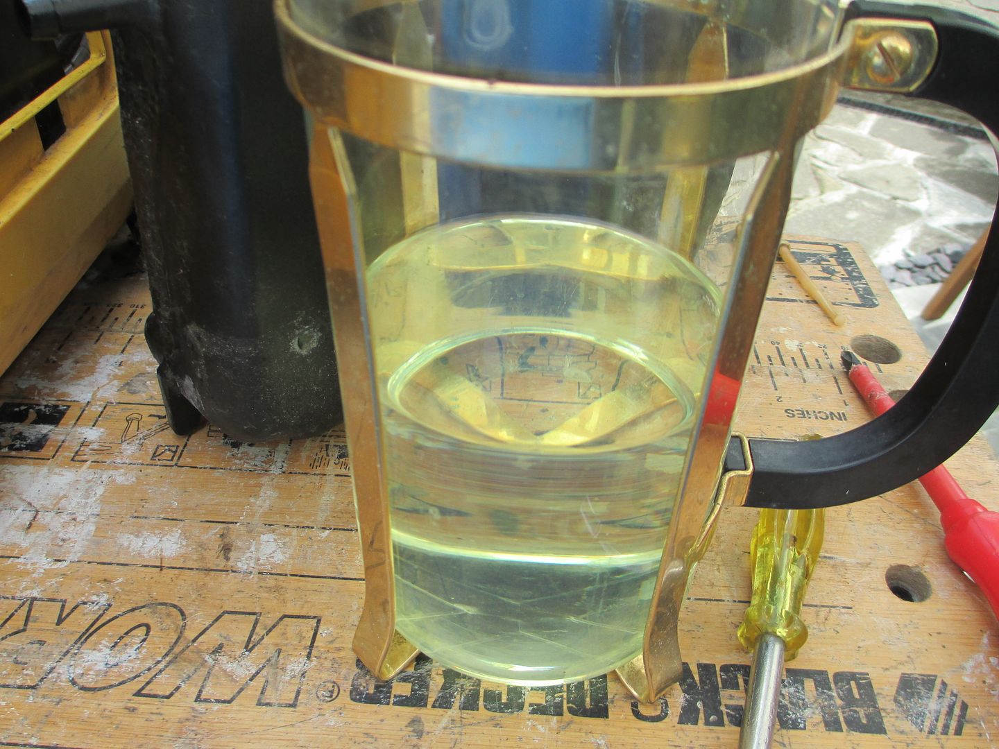
And after a fuel pulls it spluttered in to life, so all it needed was fresh fuel. I like these zero cost fixes.
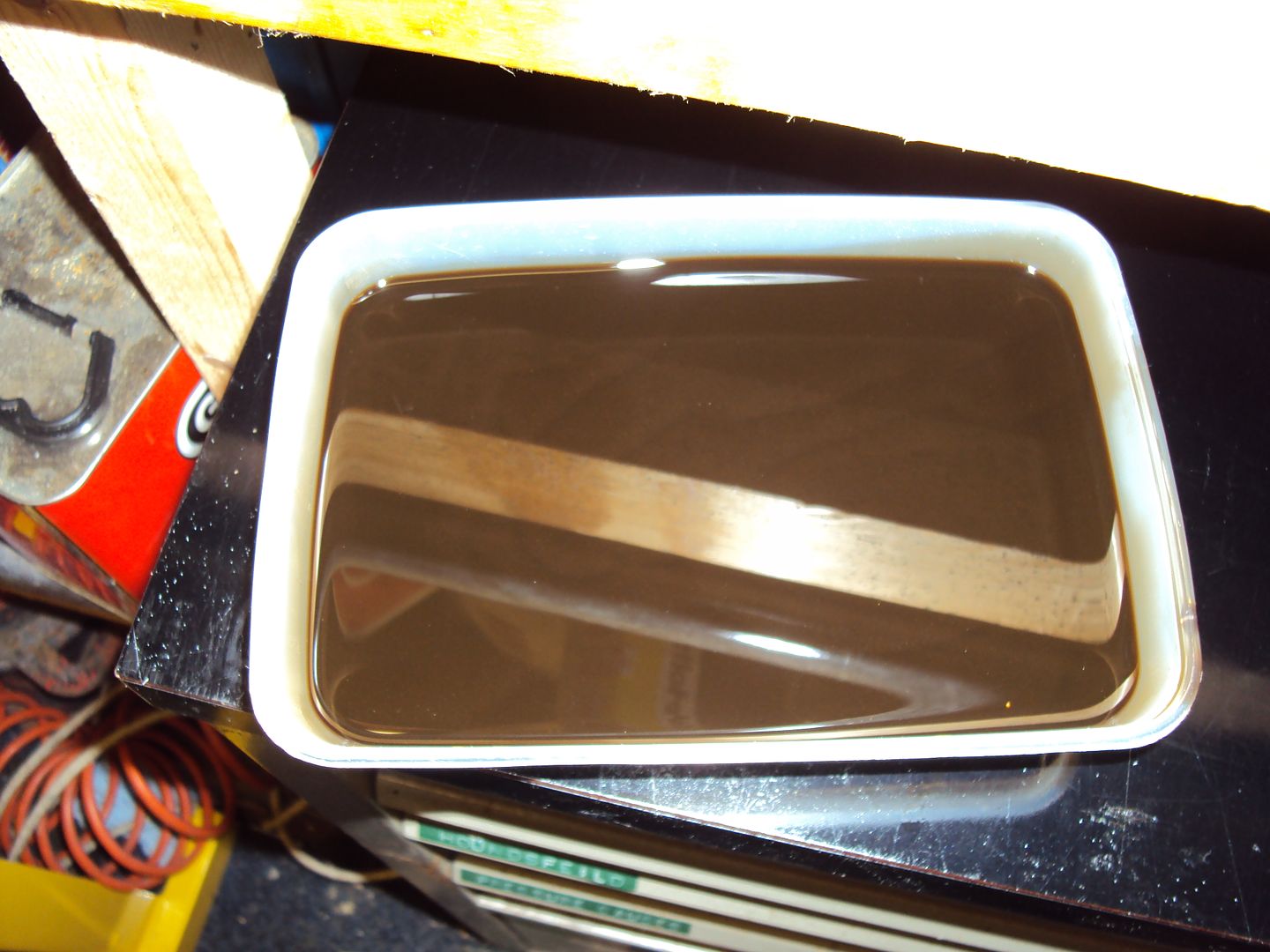
Once it had been running for a while I thought it would be good to change the oil as I don’t know how old it is.
Top Tip (ala Edd China) use a bit of card to direct the oil out of the case. (sorry for the out of focus photo)
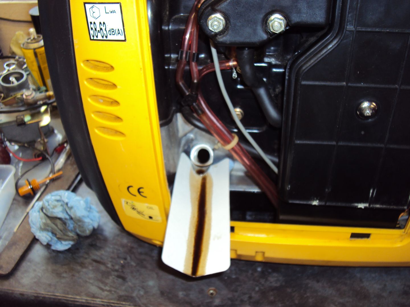
If you don’t the oil will spill inside and run down the front of the case and all over the bench. (I found out the hard way, hot engine oil moves very quickly)
The oil was quite black, (not brown like the photo)
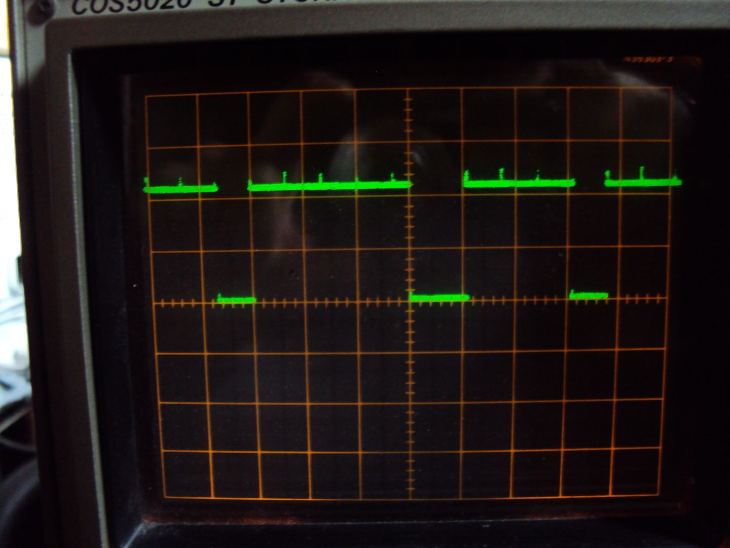
Once fresh oil was added I started it up and hooked it up to the oscilloscope just to see what the output was like.
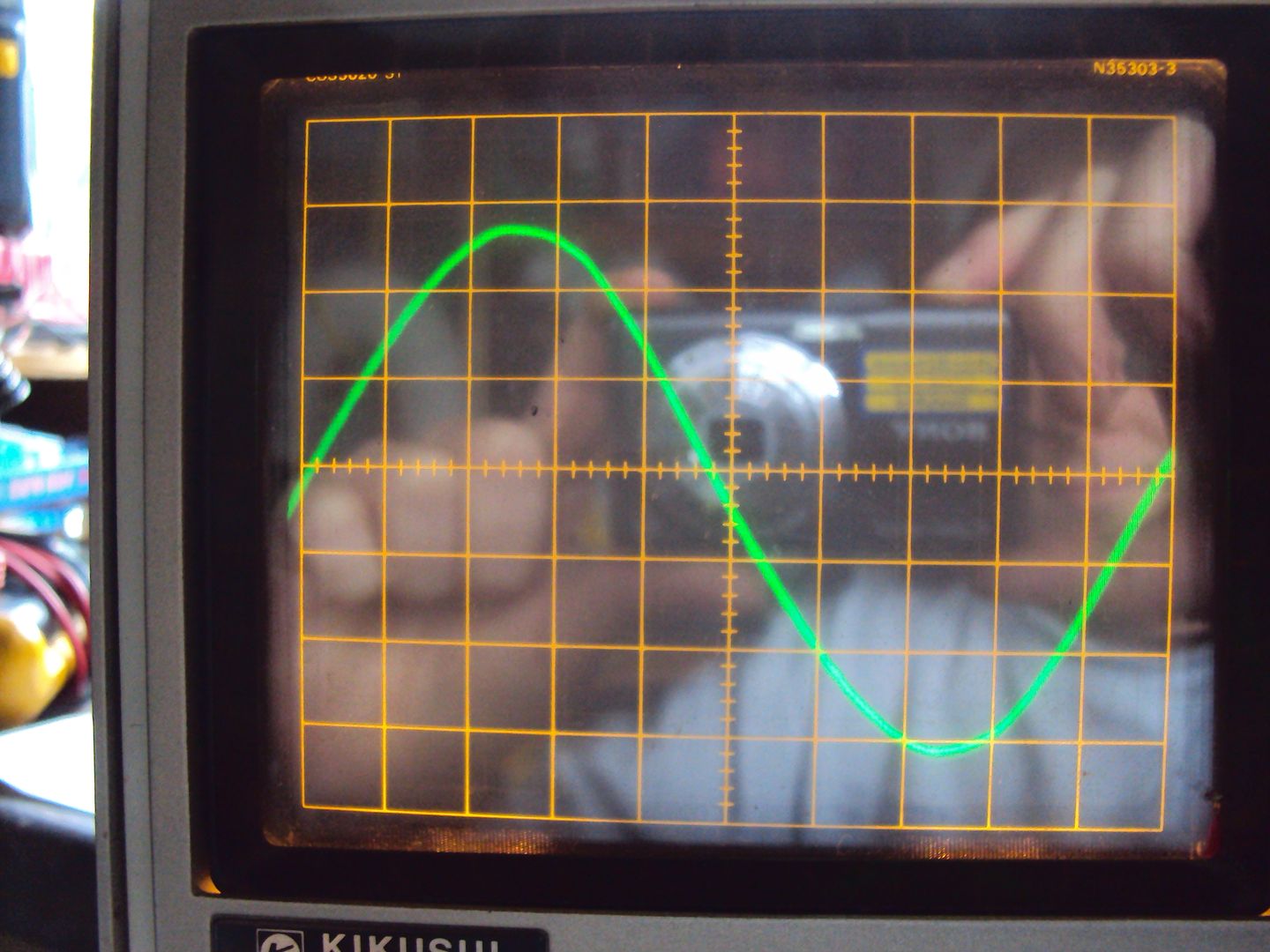
spot on 50HZ
This generator is an inverter type, the alternator puts out 3 phase (I think) which is converted to DC, then back to AC using electronics. This gives a nice clean AC signal which is why this type of generator is good for use with sensitive electronics.
For reference this it the output of the Big Honda I started this thread with.
The fault with this one was that it wouldn’t start, so I started with the obvious things like checking for spark and there is fuel in it as there isn’t much else that can go wrong. The spark was good, however there wasn’t any fuel getting to the carburettor.
I removed the fuel tank and drained it into a jug, as I thought the in-line fuel filter might be blocked
I’m sure petrol shouldn’t be that colour!
The fuel filter is held in the fuel pipe, the filter didn’t look too bad.
I cleaned the filter and put some fresh petrol in the tank
And after a fuel pulls it spluttered in to life
, so all it needed was fresh fuel. I like these zero cost fixes.Once it had been running for a while I thought it would be good to change the oil as I don’t know how old it is.
Top Tip (ala Edd China) use a bit of card to direct the oil out of the case. (sorry for the out of focus photo)
If you don’t the oil will spill inside and run down the front of the case and all over the bench. (I found out the hard way, hot engine oil moves very quickly)
The oil was quite black, (not brown like the photo)
Once fresh oil was added I started it up and hooked it up to the oscilloscope just to see what the output was like.
spot on 50HZ
This generator is an inverter type, the alternator puts out 3 phase (I think) which is converted to DC, then back to AC using electronics. This gives a nice clean AC signal which is why this type of generator is good for use with sensitive electronics.
For reference this it the output of the Big Honda I started this thread with.
We went a bit mad over the bank holiday weekend and bought 2 more generators. The first was another Kipor suitcase identical to the last one. The description of the fault was:
“Engine will not run. It starts, splutters and stops - and very often will not start at all. I have no idea what is wrong, nor if it will generate once the engine is running.”
I took a chance thinking it was the stepper motor which operates the throttle as this is the most likely cause.
On disassembly we found the fuel pipe from the tank had a kink preventing the fuel from flowing
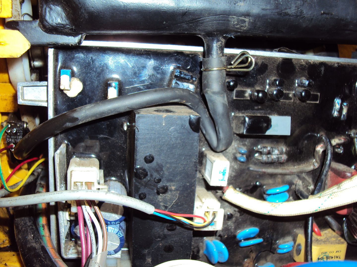
And that the ignition control unit was unplugged.
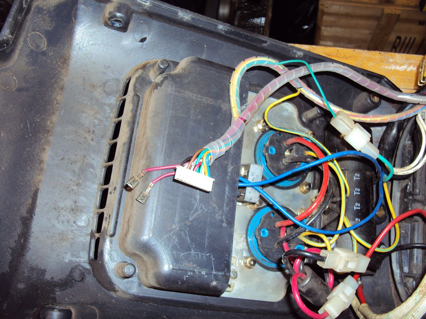
As soon as these were rectified, it started straight away, however it wasn’t outputting any power. After some further testing we determined the inverter unit was at fault.
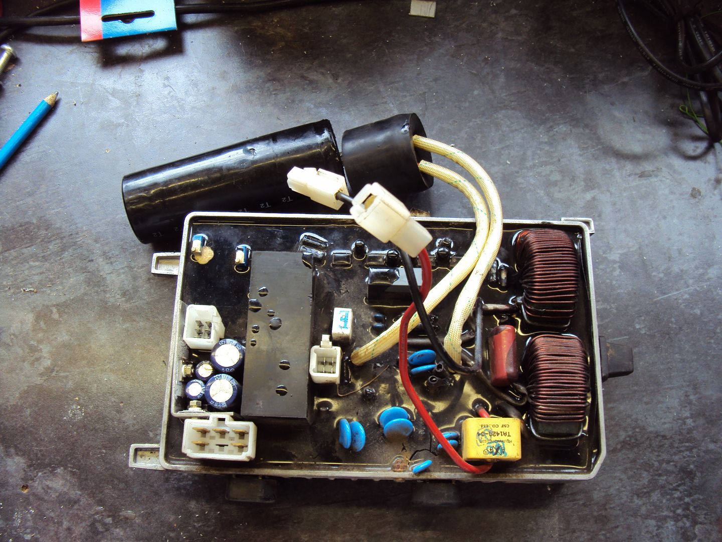
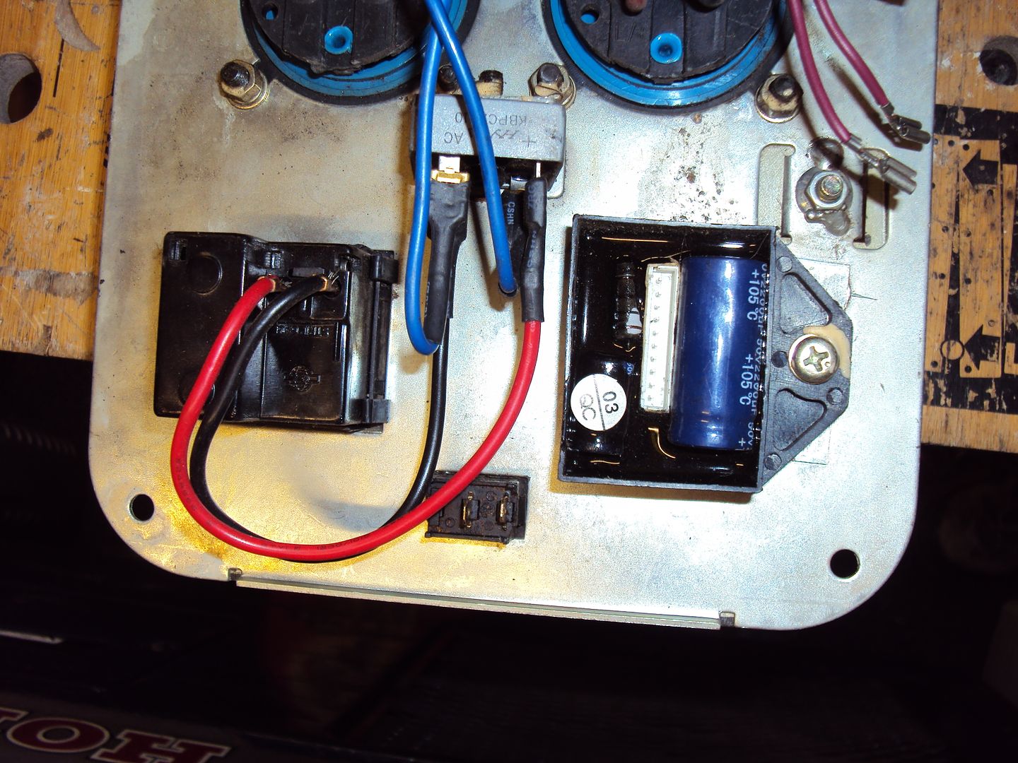
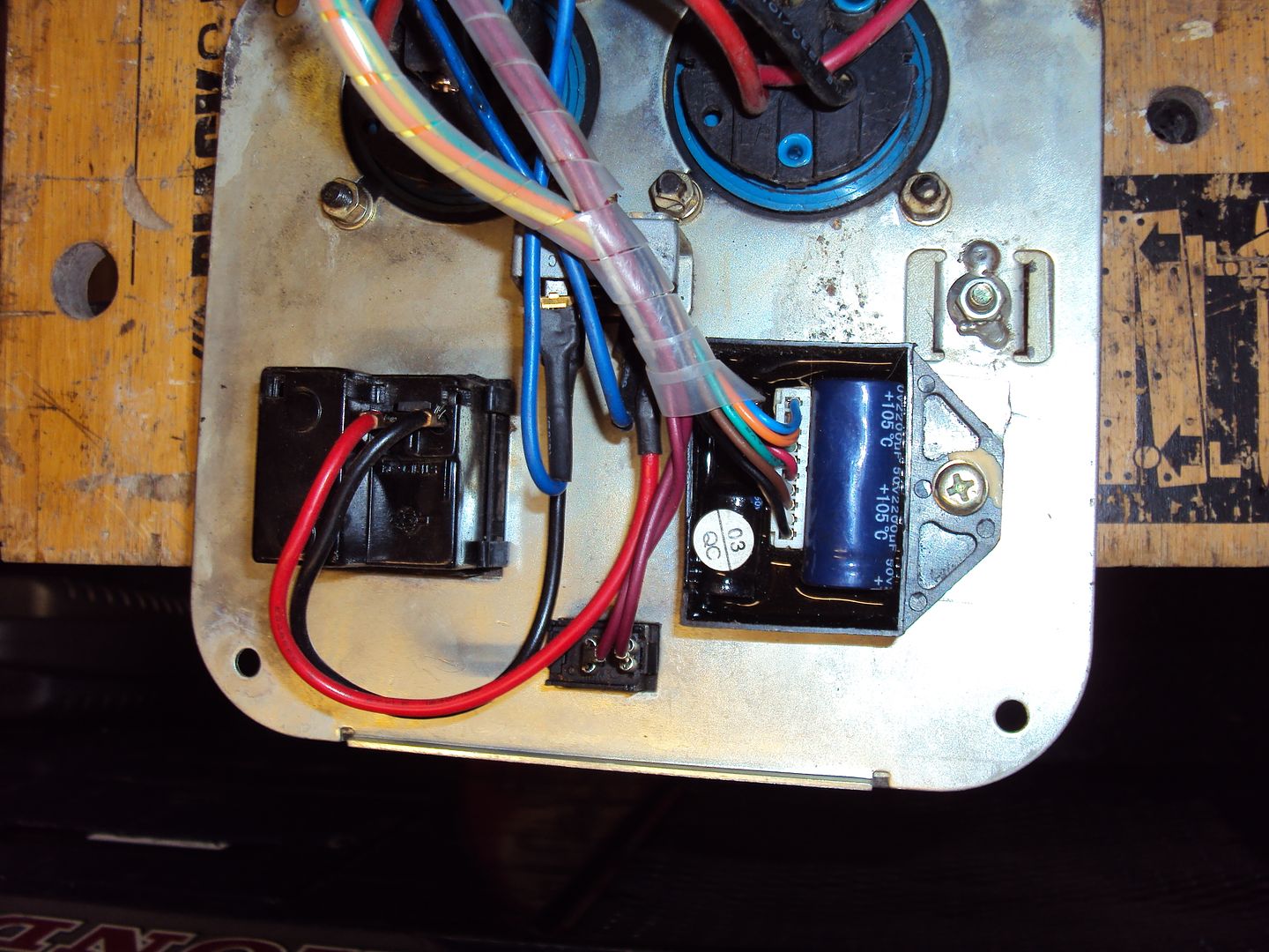
I thought there might be an easy fix as the capacitor wasn’t looking too healthy as it was bulging
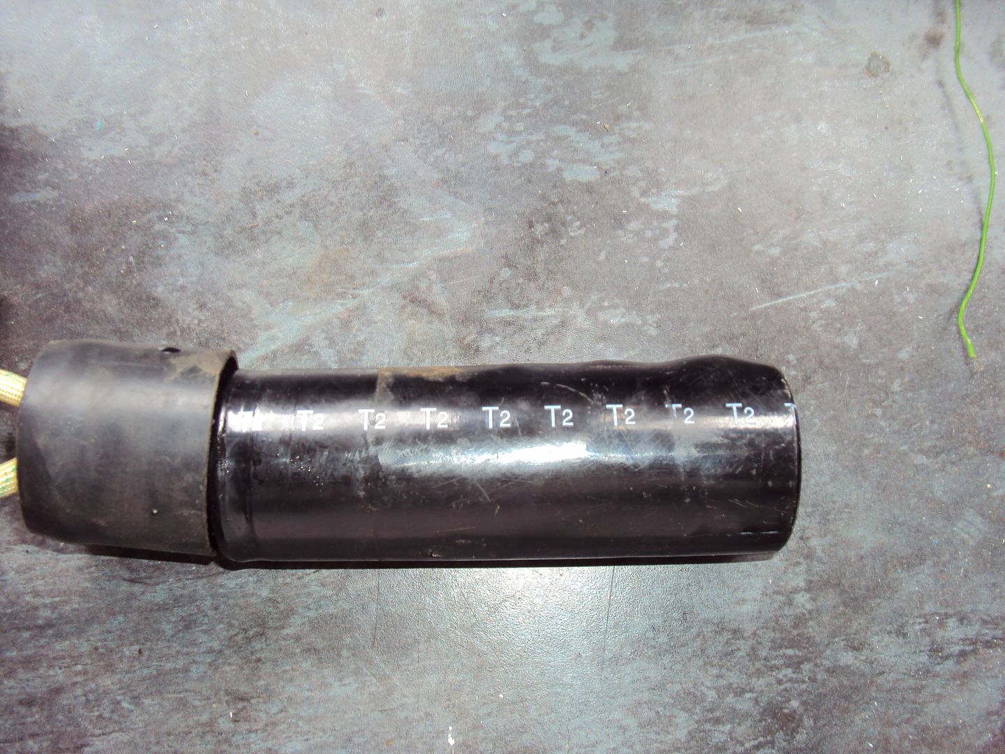
After a quick test the capacitor was found to be ok, so it looks like the fault is inside the inverter unit with no chance if repair as it is all potted.
I’m currently deciding how to proceed with this one as the replacement inverter costs nearly as much as a working unit sells for.
On to the second one we bought.
This one was described as was running then put into storage and is now seized. When we started looking at it we found the engine would turn for about ¾ of a revolution before hitting something. We thought maybe a valve was either stuck or broken so started disassembly.
Need to add an exhaust to the parts list..
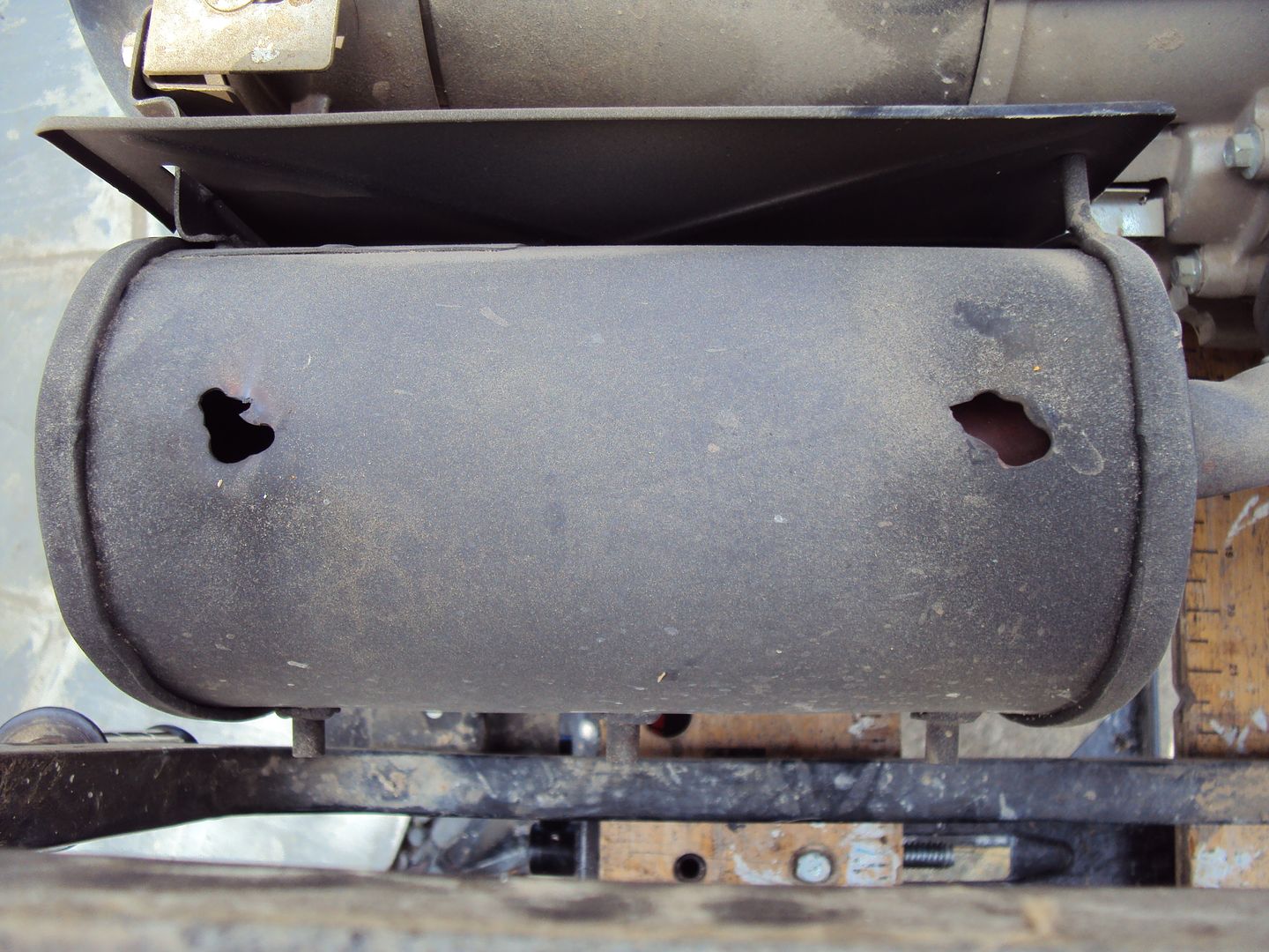
Exhaust and carburettor removed
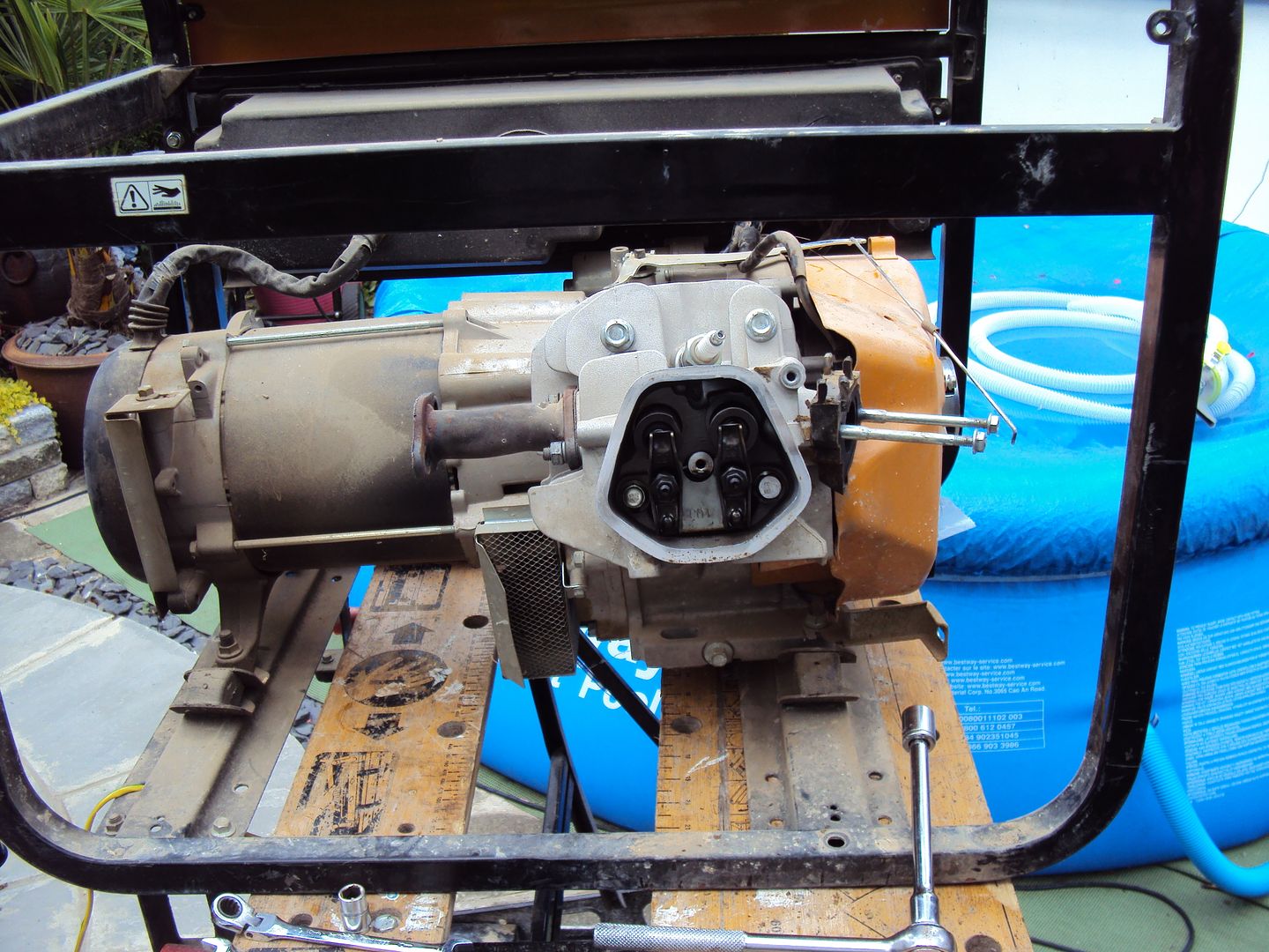
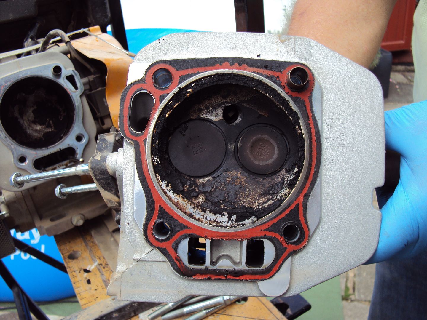
Head off, valves look ok
Piston
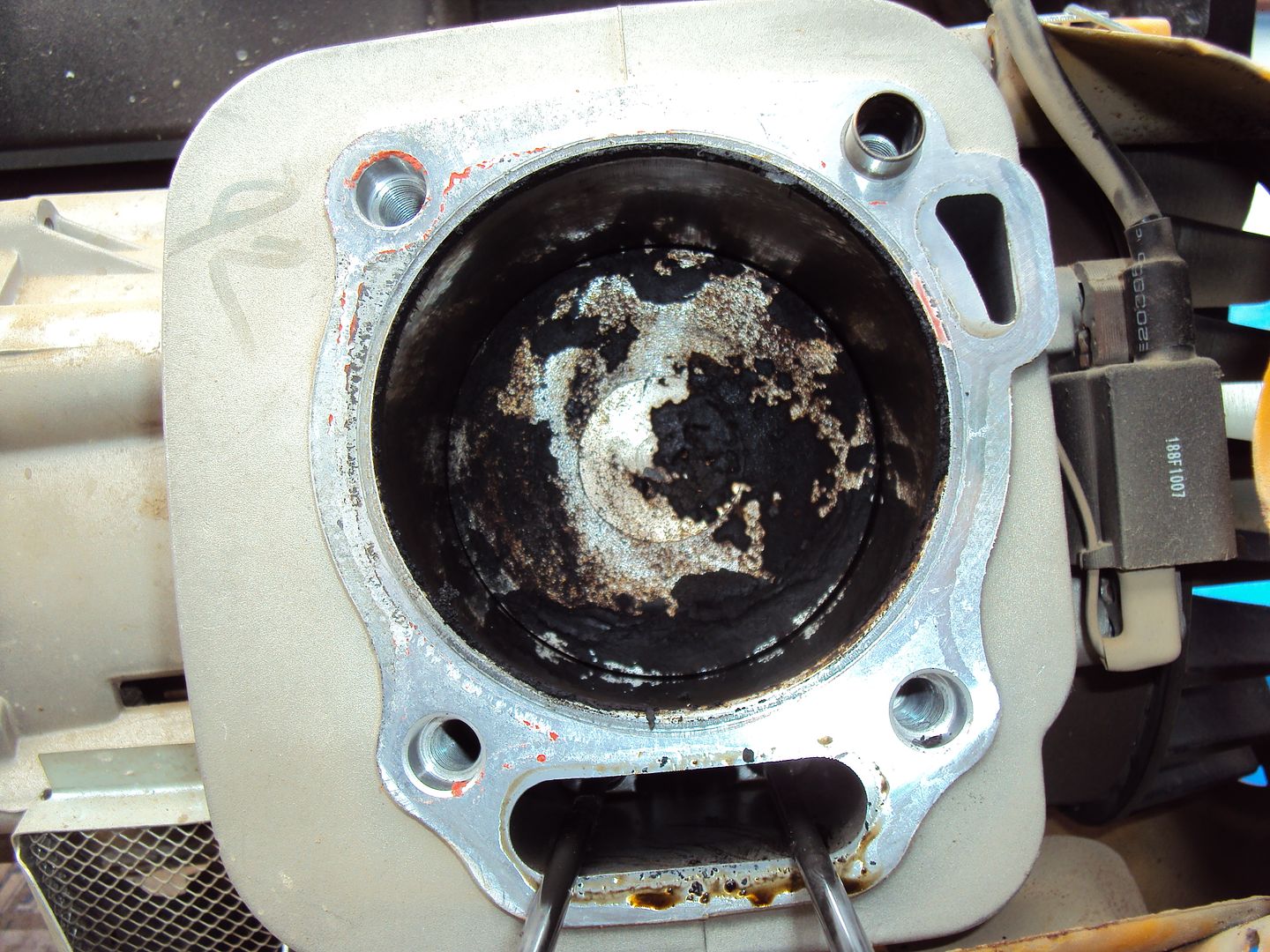
The engine turned freely with the head removed, so we guessed it was all the carbon stopping the piston from going all the way to the top.
We cleaned all the carbon from the head and piston and reassembled the engine, (sorry forgot to take pictures) and got it running.
Just need to find someone to weld the exhaust, all though I am looking at the possibility of buying a MIG or TIG welder.
If there are any PH’rs in the Orpington/ Chislehurst area that fancy practising their welding skills in exchange for beer/beer tokens drop me a pm.
“Engine will not run. It starts, splutters and stops - and very often will not start at all. I have no idea what is wrong, nor if it will generate once the engine is running.”
I took a chance thinking it was the stepper motor which operates the throttle as this is the most likely cause.
On disassembly we found the fuel pipe from the tank had a kink preventing the fuel from flowing
And that the ignition control unit was unplugged.
As soon as these were rectified, it started straight away, however it wasn’t outputting any power. After some further testing we determined the inverter unit was at fault.
I thought there might be an easy fix as the capacitor wasn’t looking too healthy as it was bulging
After a quick test the capacitor was found to be ok, so it looks like the fault is inside the inverter unit with no chance if repair as it is all potted.
I’m currently deciding how to proceed with this one as the replacement inverter costs nearly as much as a working unit sells for.
On to the second one we bought.
This one was described as was running then put into storage and is now seized. When we started looking at it we found the engine would turn for about ¾ of a revolution before hitting something. We thought maybe a valve was either stuck or broken so started disassembly.
Need to add an exhaust to the parts list..
Exhaust and carburettor removed
Head off, valves look ok
Piston
The engine turned freely with the head removed, so we guessed it was all the carbon stopping the piston from going all the way to the top.
We cleaned all the carbon from the head and piston and reassembled the engine, (sorry forgot to take pictures) and got it running.
Just need to find someone to weld the exhaust, all though I am looking at the possibility of buying a MIG or TIG welder.
If there are any PH’rs in the Orpington/ Chislehurst area that fancy practising their welding skills in exchange for beer/beer tokens drop me a pm
. Gassing Station | Homes, Gardens and DIY | Top of Page | What's New | My Stuff