One for the sparkys - wiring of a flex outlet in new house
Discussion


Hi Guys
looking for some help with this one, in the utility room of the house we have just moved into I have found the usual and also some wiring I don't quite understand, to list of what its in there.
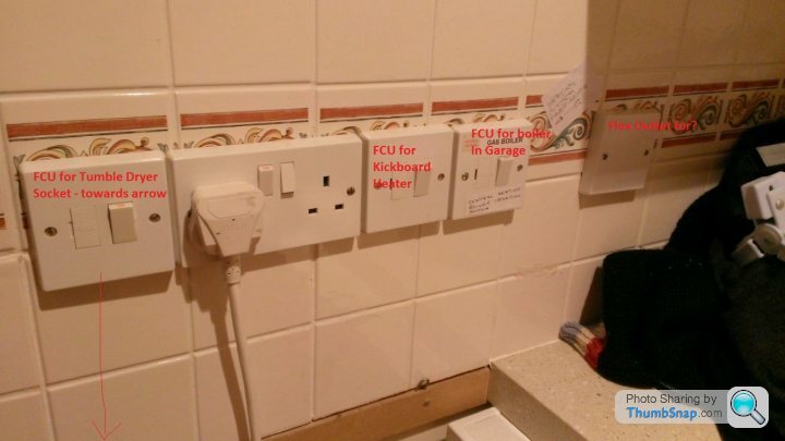
Fused switch connected to socket for Fridge
Fused switch connected to kickboard heater
Fused switch connected to Central Heating Pump (boiler in the garage)
Flex outlet which I cant work out what it is connected to... (question below)
3 Way Light Switch..
1) Connected to the light
2) Connect to the utility room extractor fan (previous owners must have had wet dogs I presume..)
3) Connected to the outside PIR Lights
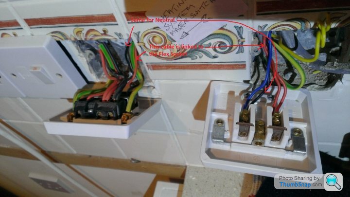
I basically want to remove the flex outlet and put in a standard socket, but as you can see in the pics of the flex outlet I don't understand why its wired like this, and also why would you keep this and not simply install a socket? makes no sense

The things I cant work out is...
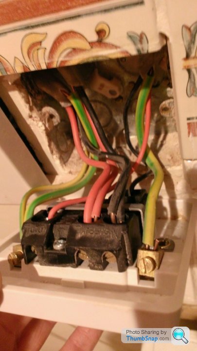
1) why is the flex outlet wired the wrong way round
2) There also appears to be an extra "outlet" not even terminated! (worrying)
3) The extra yellow wire - I was thinking perhaps this was wired into an older extraction fan and used for the light switch?
4) why they choose those beautiful tiles
I have tested the cables connected at the moment, and they are live so its not unused..
any thoughts/pointers appreciated
GP
looking for some help with this one, in the utility room of the house we have just moved into I have found the usual and also some wiring I don't quite understand, to list of what its in there.
Fused switch connected to socket for Fridge
Fused switch connected to kickboard heater
Fused switch connected to Central Heating Pump (boiler in the garage)
Flex outlet which I cant work out what it is connected to... (question below)
3 Way Light Switch..
1) Connected to the light
2) Connect to the utility room extractor fan (previous owners must have had wet dogs I presume..)
3) Connected to the outside PIR Lights
I basically want to remove the flex outlet and put in a standard socket, but as you can see in the pics of the flex outlet I don't understand why its wired like this, and also why would you keep this and not simply install a socket? makes no sense
The things I cant work out is...
1) why is the flex outlet wired the wrong way round
2) There also appears to be an extra "outlet" not even terminated! (worrying)
3) The extra yellow wire - I was thinking perhaps this was wired into an older extraction fan and used for the light switch?
4) why they choose those beautiful tiles
I have tested the cables connected at the moment, and they are live so its not unused..
any thoughts/pointers appreciated
GP
Edited by gcpeters on Monday 30th November 10:53
Thanks for the replies everyone, much appreciated and the investigation continues (I finally had some time last night to have a quick look)
so to answer some more questions
1) The grey flex is indeed 2 core + Earth, it is not live
2) The wiring as pointed out is indeed 1.5MM so not the correct spec for sockets at the moment
I took the adjacent FCU out, which is for the boiler and it looks like they have ran a spur from this to the mysterious "Flex Outlet" socket on the right! The Flex socket is wired on the ring circuit to the consumer unit..
See pics below for more details..
so something is definitely not right here, did they take a feed of the ring circuit for a lighting circuit? surely not?
GP
Simpo Two said:
My thought was the old T&E had once powered a socket there, so if you can 're-liven' it, throw away the small wires that don't do anything and swap the panel for a 13A socket you've achieved your aim 
That was my thought, I just have to try and find where it goes - which could be a challenge! Other option I guess is to run another T&E across and make it into a new spur...Im still not sure why though they are spurring of the central heating FCU into the "Flex" socket with the 1.5 MM cable though... hmmmm
Gassing Station | Homes, Gardens and DIY | Top of Page | What's New | My Stuff