Celica ST205 GT4 - Phase 2!
Discussion


Feb 19th - 2012
Good morning chaps,
I have been looking for an ST205 for quite some time, putting in a concerted effort since seeing one blatting round the roads at the base of snowdon thorugh the snow.
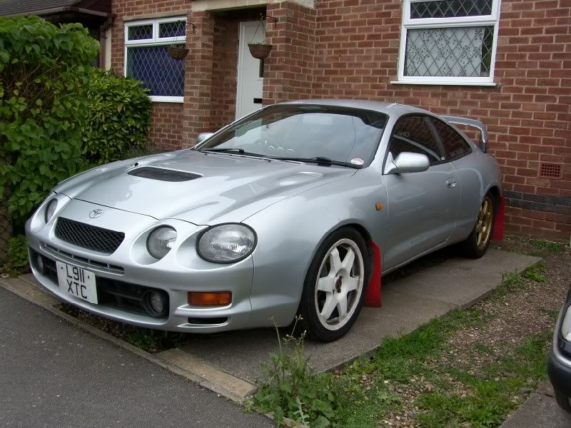
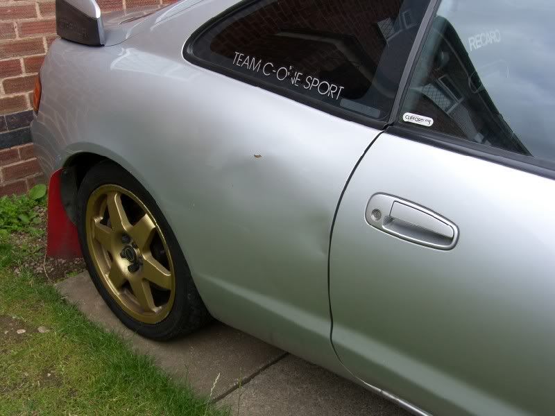
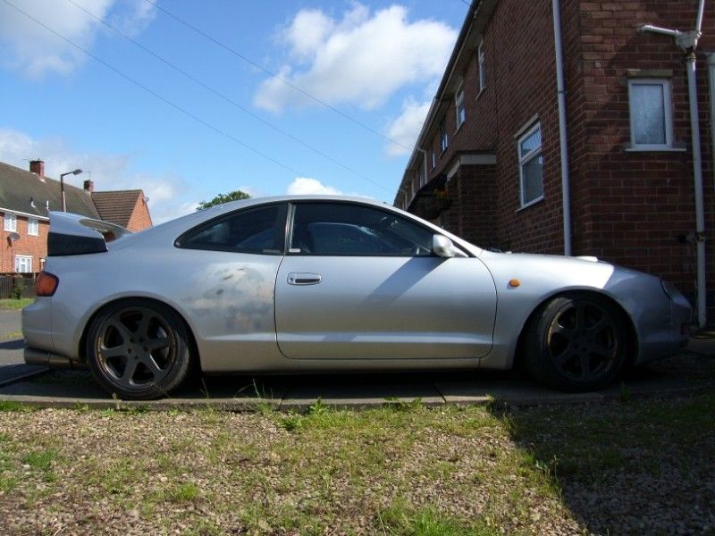
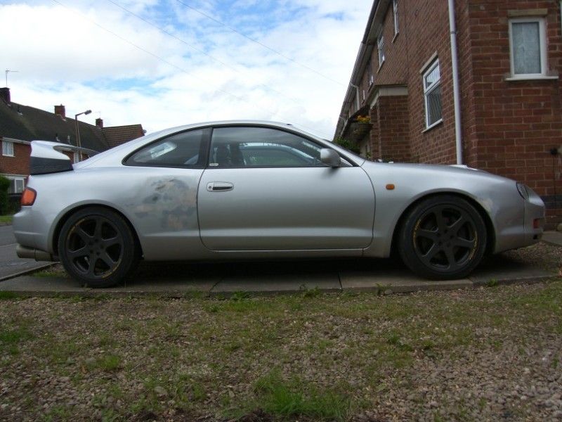
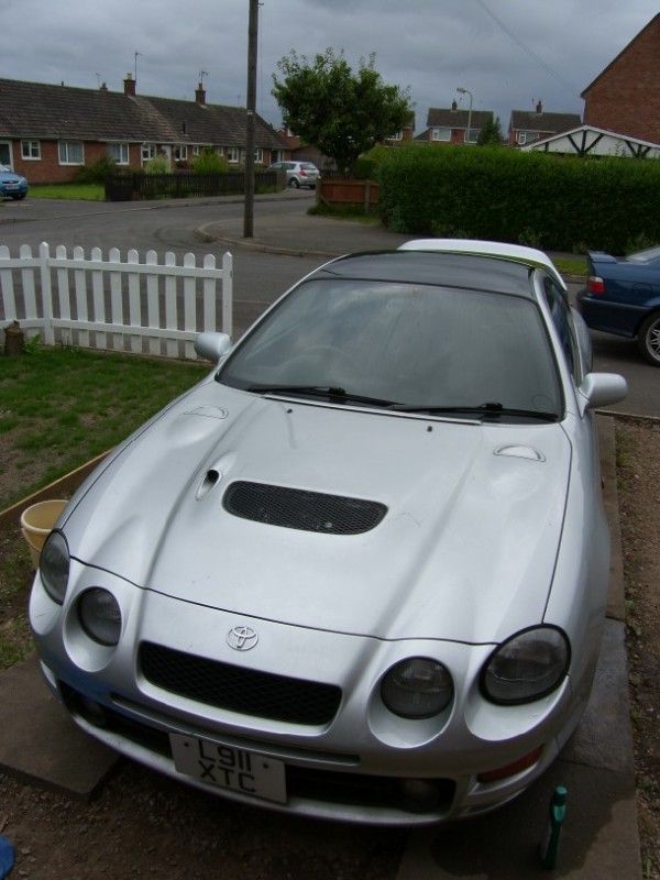
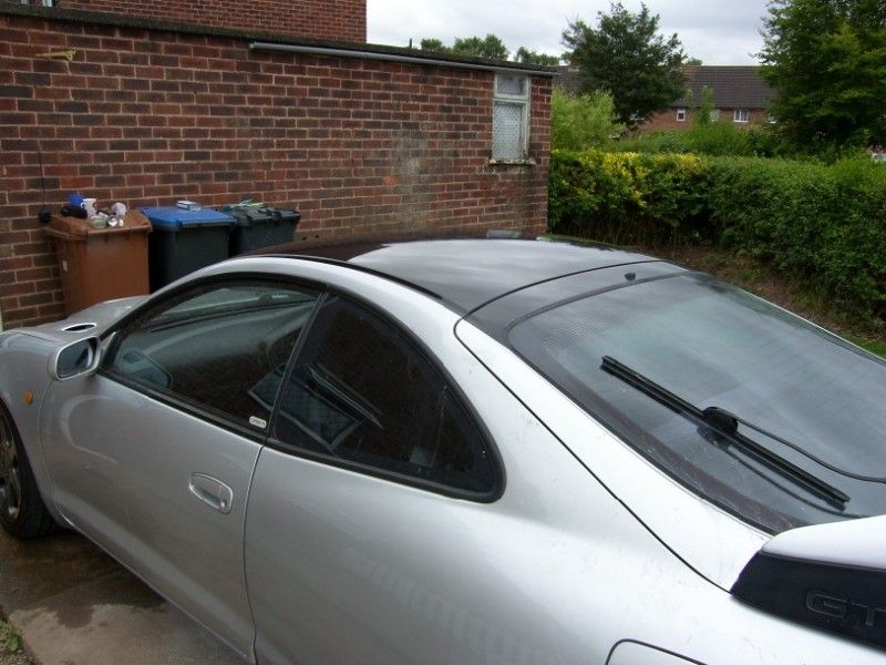
Now I like my projects, and in full understanding of the issues involved I went to look at an ST205 with a slipping clutch yesterday, the result is this -
Yes the wheels don't match, and it is in need of work, but there is a good history file and the slipping clutch led me to finding this in the folder -
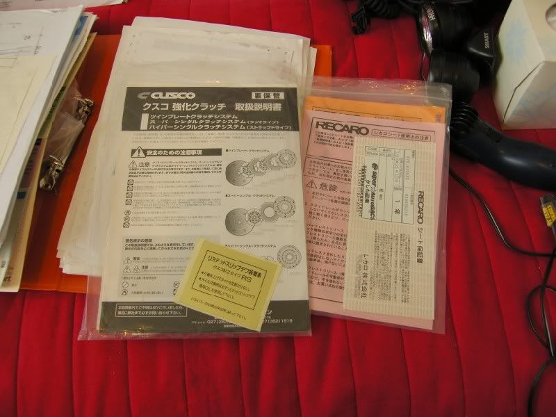
Hmmmm, Cusco super single clutch kit? No wonder it is worn out! A sintered plate on a road car is generally a bad idea, slipping to get out of junctions is going to rape the plate in double time :?
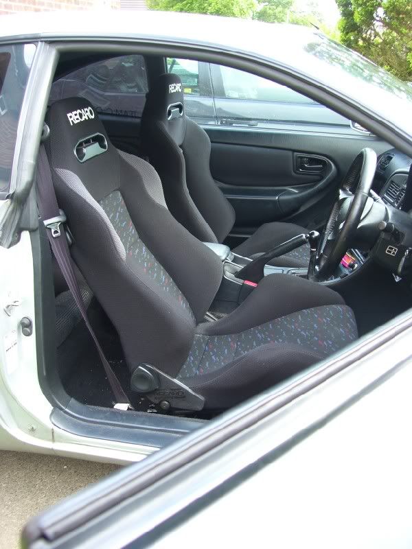
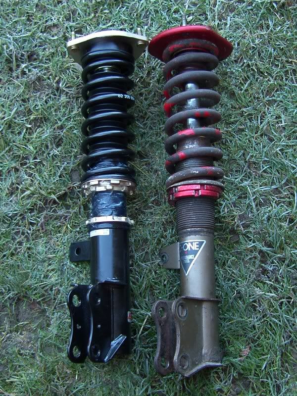
Either way, it has some shiny bits, C-One coilovers (in need of a rebuild, might tackle this one myself), C-One exhaust, recent cambelt and service, Recaro seats in jolly good condition, all in all not too bad.
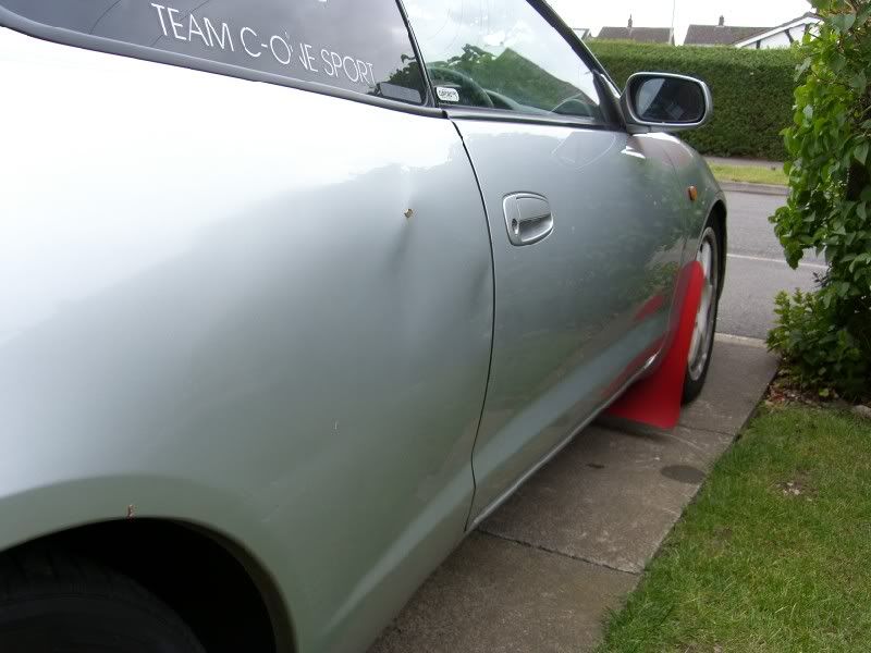
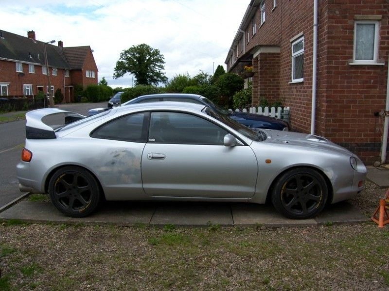
So bits to sort out, are wheels (get those pesky subaru speedlines off the back end), this little bump on the drivers rear quarter -
And start looking into the what wheres and hows of this Cusco clutch.
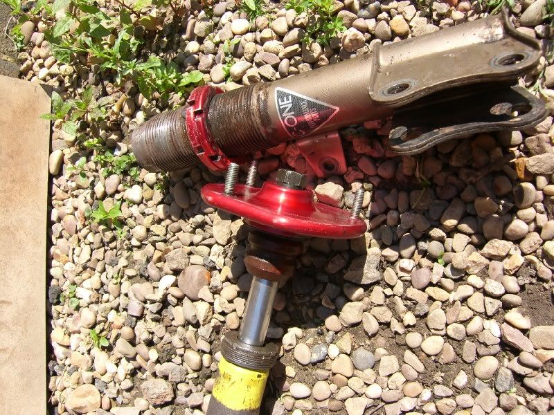
First mechanical items to be attacked were the coilovers, I could see that a couple were leaking and knowing from literature the complexities of the SS front end, I started with the rear McPhersons.
Here is the image the greeted me once the wheels was removed -
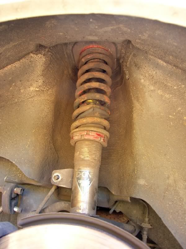
C-One coilover set up, I removed the assembly and started to dissasemble and clean, using my old favourite bio washing powder, nasty for your skin, but excellent on oils! -
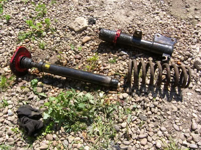
The results -
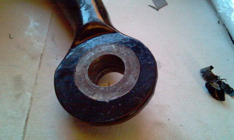
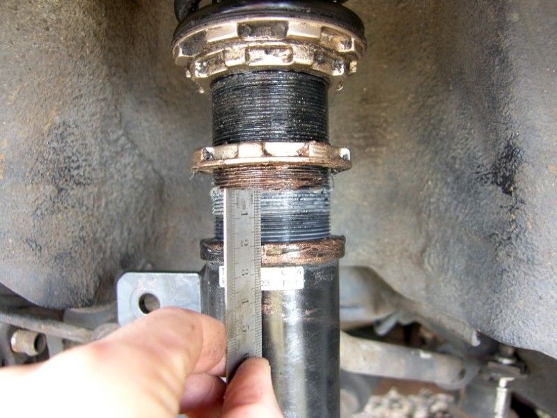
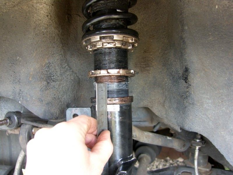
As you can see, here is the reason it was leaking -
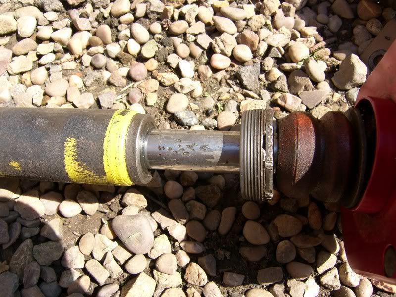
Badly pitted shaft! They have been moving around in the housing too, gland nut was not properly tightened -
So I am now looking to replace the damper inserts, probably all round TBH, I have the dimensions but I have no idea where to get replacements as I want non adjustable items with a reasonably complient damping rate, the car is to be a B road stormer not a track tart! :lol:
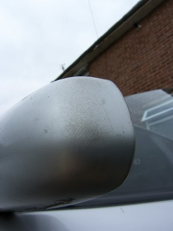
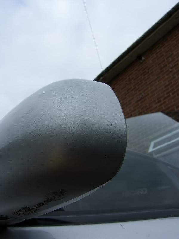
I also had a quick look at some of the paint issues, first up the passenger wing mirror, the finish was terrible with what can only be described as 'hatchings' in the surface -
10 mins with two grades of cutting compound and a polish, the not perfect but much better results -
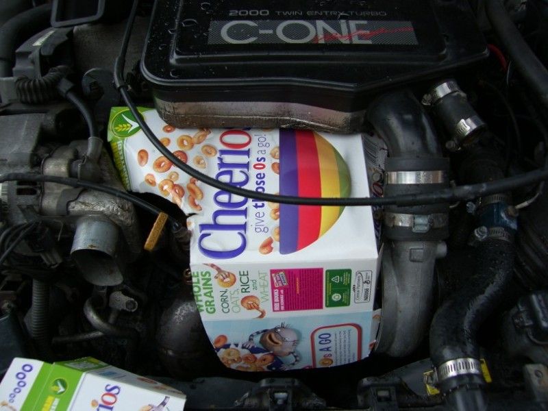
Finally, why milky? Well while I was messing around getting my hands dirty, my wife was cleaning the inside, and under the spare wheel she found no less than 9 of these -
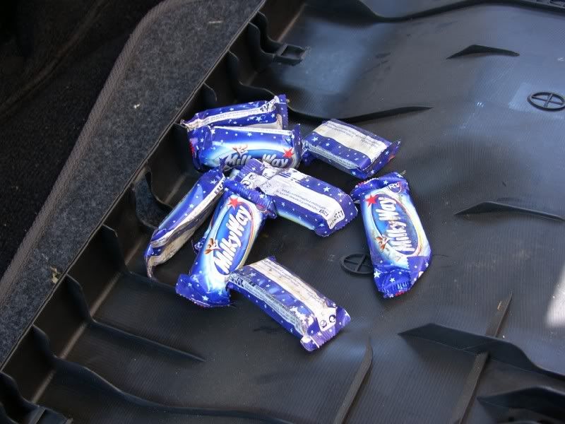
So for concealing 9 mini milky way bars, it shall be known as milky from now on :?
Keep your eyes open for updates of a more thrilling nature soon,
Cheers,
J
Good morning chaps,
I have been looking for an ST205 for quite some time, putting in a concerted effort since seeing one blatting round the roads at the base of snowdon thorugh the snow.
Now I like my projects, and in full understanding of the issues involved I went to look at an ST205 with a slipping clutch yesterday, the result is this -
Yes the wheels don't match, and it is in need of work, but there is a good history file and the slipping clutch led me to finding this in the folder -
Hmmmm, Cusco super single clutch kit? No wonder it is worn out! A sintered plate on a road car is generally a bad idea, slipping to get out of junctions is going to rape the plate in double time :?
Either way, it has some shiny bits, C-One coilovers (in need of a rebuild, might tackle this one myself), C-One exhaust, recent cambelt and service, Recaro seats in jolly good condition, all in all not too bad.
So bits to sort out, are wheels (get those pesky subaru speedlines off the back end), this little bump on the drivers rear quarter -
And start looking into the what wheres and hows of this Cusco clutch.
First mechanical items to be attacked were the coilovers, I could see that a couple were leaking and knowing from literature the complexities of the SS front end, I started with the rear McPhersons.
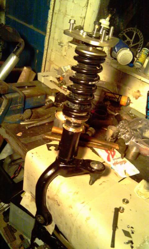
Here is the image the greeted me once the wheels was removed -
C-One coilover set up, I removed the assembly and started to dissasemble and clean, using my old favourite bio washing powder, nasty for your skin, but excellent on oils! -
The results -
As you can see, here is the reason it was leaking -
Badly pitted shaft! They have been moving around in the housing too, gland nut was not properly tightened -
So I am now looking to replace the damper inserts, probably all round TBH, I have the dimensions but I have no idea where to get replacements as I want non adjustable items with a reasonably complient damping rate, the car is to be a B road stormer not a track tart! :lol:
I also had a quick look at some of the paint issues, first up the passenger wing mirror, the finish was terrible with what can only be described as 'hatchings' in the surface -
10 mins with two grades of cutting compound and a polish, the not perfect but much better results -
Finally, why milky? Well while I was messing around getting my hands dirty, my wife was cleaning the inside, and under the spare wheel she found no less than 9 of these -
So for concealing 9 mini milky way bars, it shall be known as milky from now on :?
Keep your eyes open for updates of a more thrilling nature soon,
Cheers,
J
22nd Sep 2011
220911
Right bit of an update,
First things first, Milky ate my mobile phone! I was working on the car when it started to rain, so I gathered up the tools and made my way back indoors for a coffee, I thought ‘just check gt4oc on my phone, see whats going on…..hmmmm, where is my phone?’ Well after a bit of a search I realised I had left in under the bonnet of the celica, right under the hinges, screen up! Balls! Quick call to the insurance company (house phone!) and it is off to the menders
So please excuse the poor photos, I had to dig out my old digi cam and it seems to have deteriorated over time (I think tech has moved on but I’m in denial!).
So progress over the past couple of weeks has included a lot of calculations to confirm my suspension and spring choice, I have ended up ordering BC’s with a 6/4kg/mm spring rate. Here are the excerpts from the suspension thread I had –
[quote] I could go for stock setup for compliancy, but it will still cost £500 - £550. Coilovers are £600 and I can choose the spring rate I want FOC, so that is the main reason I will be going for them.
So my what spring rate should I go for? My initial thoughts are that the vertical stiffness of the car should be as low as possible without bottoming out the dampers under hard cyclic compression. Secondly I would like to reduce the ST205’s tendency to understeer one way or another.
Here are the current available systems -
Stock springs - Front: ~2.5 kg/mm Rear: ~2.1 kg/mm
Ratio of 1.19 stiffer front to rear.
Tein uprated springs - Front: 4.3 kg/mm Rear: 3.7 kg/mm
Ratio of 1.16 stiffer front to rear.
BC Std springs – Front: 8kg/mm Rear: 5kg/mm
Ratio of 1.6 stiffer front to rear
Looking at the numbers, the stock set up is 20% stiffer front to rear, this is directly in line with the weight distribution of the car being 60/40. The Tein setup is 16% stiffer front to rear making the rear of the car stiffer in proportion, hopefully reducing understeer, but as a consequence the vertical stiffness increases making the rear ride bouncy. The BC setup is 60% stiffer front to rear! This theoretically will make the car understeer more than the stock setup and increase the vertical stiffness of the car by 320% at the front, as far as I am concerned this is too much for my requirements.
So, I think that I will order 6kg/mm front and 5kg/mm rear, this should maintain the stock 20% front to rear stiffness ratio. Then to reduce inherent understeer without sacrificing supple vertical movement I will re-drill my rear arb to move the connection points inwards, effectively stiffening it up and reducing understeer.
[/quote]
[quote] Right, I have with a little assistance from one of my colleagues (cheers Ed!) come to a conclusion on the initial springs rates, using some simple mathematics and his experience in setting up different cars for different conditions.
The best starting point for choosing springs rates is to work out the natural resonant frequency of the front and rear axles, this can be determined using the sprung and un-sprung masses.
Initially the standard suspension was analysed, this is using a UK car and averaging the corner weights, standard springs etc.
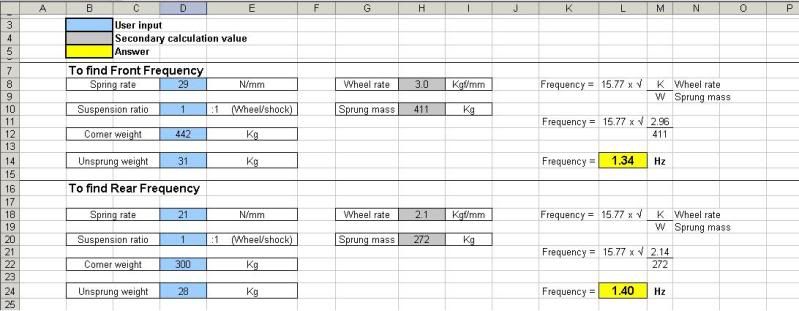
As you can see they are not matched, resulting in the front and rear of the car reacting in a different manner over the same bump. The aim when setting the car up is to achieve the same frequency front and rear.
Now the standard suspension frequency is known I can design the system around it, using the following calculated figures for previous cars Ed has set up –
106 GTI (fast road) - 1.87Hz - Perfect for B roads, wobbly on track
205 GTI (Gravel) - 2.0Hz - Very nice setup for real world road use, a bit soft for track and sticky tires
205 GTI (Hillclimb) - 2.99Hz - Bit to stiff and jolty on roads,
My escort (Mental, was 4age20v now SR20, gotta explain ed!) – 2.4Hz ish - Feels very good on roads, might be slightly soft for hardcore tracking
Civic (Britcar) - 3.5Hz - To harsh for fast road use without skipping, could do with being a bit stiffer when stickier slicks were used
Lotus 211 (BritishGT) - 4.5Hz - Proper slicks and a bit of down force
My car as I keep bleeting on about, will be a B road car, set up for fast road use on give and take roads around the midlands and wales. I will be aiming for around 2Hz, to reach a viable spring rate I have gone for 2.05Hz, this equates to 7Kgf/mm front and 4.6Kgf/mm rear.
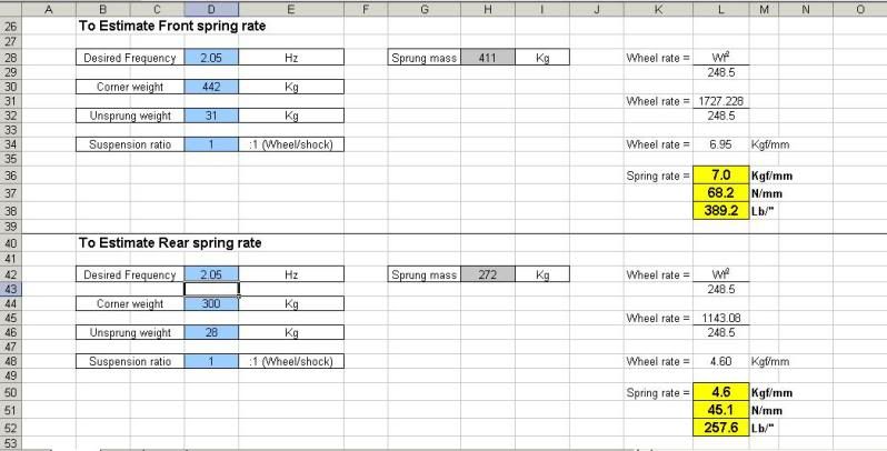
So after going through the calcs here are the results for the other springs and suspension systems available –
Stock springs - Front: ~2.5 kgf/mm Rear: ~2.1 kgf/mm
Front – 1.34Hz
Rear – 1.4Hz
Tein uprated springs - Front: 4.3 kgf/mm Rear: 3.7 kgf/mm
Front – 1.63Hz
Rear – 1.86Hz
BC Std springs – Front: 8kgf/mm Rear: 5kgf/mm
Front – 2.22Hz
Rear – 2.16Hz
ST205 Bilstein Coilovers (JohnDGT4’s) – Front: 14kgf/mm Rear: 7kgf/mm
Front – 2.94Hz
Rear – 2.55Hz
(Assuming standard corner weights, I’m guessing this car has had a little more done to it though!)
So, what do you guys think? This is only the first step of course, the dampers need to be tuned to the springs, as do the ARB’s. But I also have plans there too, initially make the stock items adjustable, then possibly do a system like the citroen xsara WRC car!
[/quote]
I ended up ordering them from Corby Motorsport, the vendor was a pleasure to deal with, delivery time was spot on considering the custom spring rates, and all in it was £600!!!!! They come highly recommended from me
So the front end of the car has been stripped of it’s struts, the ball joints were not too bad, I used the big lump hammer to shock the tapers off their seats, took about 40 mins per side to remove. Once side appears to be in very good condition, the other side is in need of a fig8, not too bad though. Both of the upper ball joints need replacements before I fit the new c’overs.
Other than that I have been cleaning and tinkering, the strut brace was removed when taking the top mounts out, it is a really nice C-one unit in CNC’d aluminium, but in need of attention due to corrosion setting in on the ally. I attempted to compound it back, only the main bars responded to this, I think they were lacquered from new, all of the associated bracketry has taken a beating and just would not clean up.
C-One Strut brace –
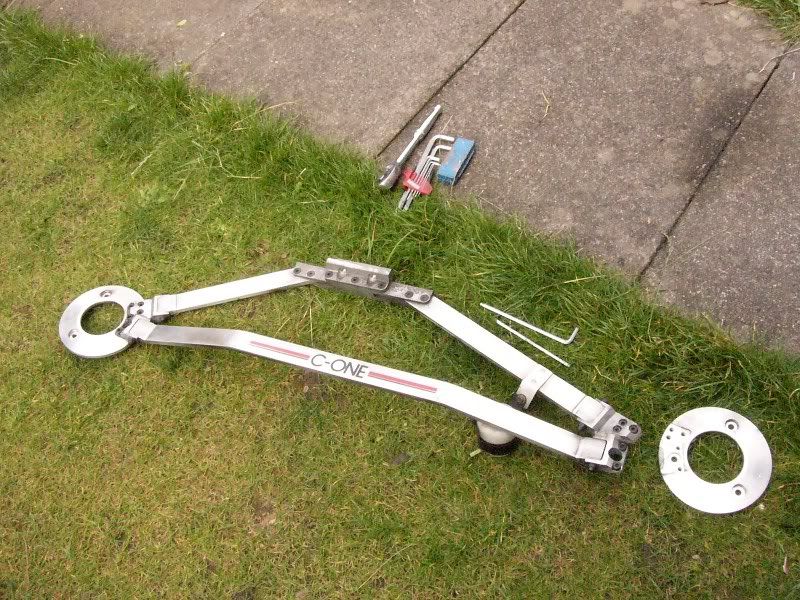
Condition of brackets –
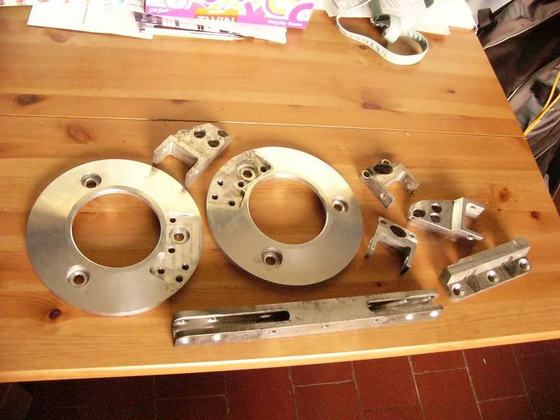
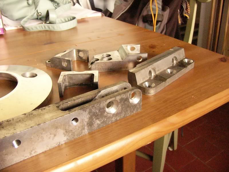
I decided to get them glass bead blasted, the result is stunning and originally I was just going to lacquer at this point, however I have been reading about home anodising, and as they have come out so good I think I should put a little more effort in, learn a new skill, and give it a go!
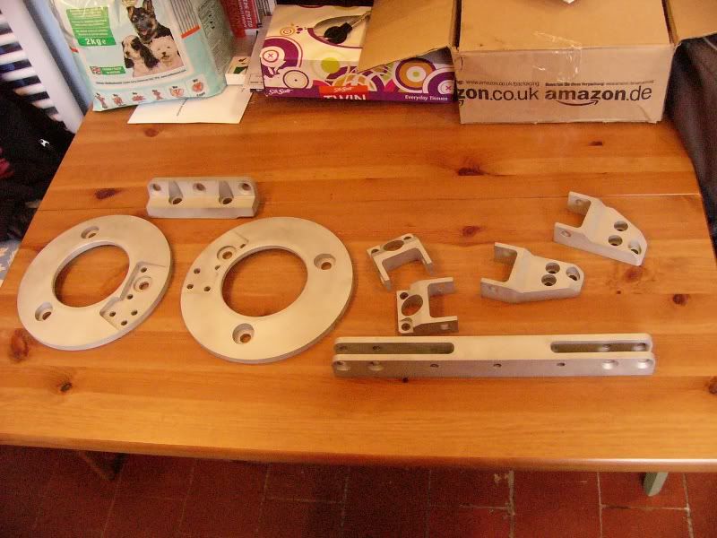
Post blasting –
Other than that, a lot of removing components and cleaning (sorry for the blown out picture!) –
And I thought I would just pop this here –
Looks rather good doesn’t it? Might have to give it a permanent home!
I will update over the next few days as I get the coilovers ready to fit, source some spacers for the back end and a set of brake pipes, and fit my new steering wheel
Hope you are all well,
J
220911
Right bit of an update,
First things first, Milky ate my mobile phone! I was working on the car when it started to rain, so I gathered up the tools and made my way back indoors for a coffee, I thought ‘just check gt4oc on my phone, see whats going on…..hmmmm, where is my phone?’ Well after a bit of a search I realised I had left in under the bonnet of the celica, right under the hinges, screen up! Balls! Quick call to the insurance company (house phone!) and it is off to the menders
So please excuse the poor photos, I had to dig out my old digi cam and it seems to have deteriorated over time (I think tech has moved on but I’m in denial!).
So progress over the past couple of weeks has included a lot of calculations to confirm my suspension and spring choice, I have ended up ordering BC’s with a 6/4kg/mm spring rate. Here are the excerpts from the suspension thread I had –
[quote] I could go for stock setup for compliancy, but it will still cost £500 - £550. Coilovers are £600 and I can choose the spring rate I want FOC, so that is the main reason I will be going for them.
So my what spring rate should I go for? My initial thoughts are that the vertical stiffness of the car should be as low as possible without bottoming out the dampers under hard cyclic compression. Secondly I would like to reduce the ST205’s tendency to understeer one way or another.
Here are the current available systems -
Stock springs - Front: ~2.5 kg/mm Rear: ~2.1 kg/mm
Ratio of 1.19 stiffer front to rear.
Tein uprated springs - Front: 4.3 kg/mm Rear: 3.7 kg/mm
Ratio of 1.16 stiffer front to rear.
BC Std springs – Front: 8kg/mm Rear: 5kg/mm
Ratio of 1.6 stiffer front to rear
Looking at the numbers, the stock set up is 20% stiffer front to rear, this is directly in line with the weight distribution of the car being 60/40. The Tein setup is 16% stiffer front to rear making the rear of the car stiffer in proportion, hopefully reducing understeer, but as a consequence the vertical stiffness increases making the rear ride bouncy. The BC setup is 60% stiffer front to rear! This theoretically will make the car understeer more than the stock setup and increase the vertical stiffness of the car by 320% at the front, as far as I am concerned this is too much for my requirements.
So, I think that I will order 6kg/mm front and 5kg/mm rear, this should maintain the stock 20% front to rear stiffness ratio. Then to reduce inherent understeer without sacrificing supple vertical movement I will re-drill my rear arb to move the connection points inwards, effectively stiffening it up and reducing understeer.
[/quote]
[quote] Right, I have with a little assistance from one of my colleagues (cheers Ed!) come to a conclusion on the initial springs rates, using some simple mathematics and his experience in setting up different cars for different conditions.
The best starting point for choosing springs rates is to work out the natural resonant frequency of the front and rear axles, this can be determined using the sprung and un-sprung masses.
Initially the standard suspension was analysed, this is using a UK car and averaging the corner weights, standard springs etc.
As you can see they are not matched, resulting in the front and rear of the car reacting in a different manner over the same bump. The aim when setting the car up is to achieve the same frequency front and rear.
Now the standard suspension frequency is known I can design the system around it, using the following calculated figures for previous cars Ed has set up –
106 GTI (fast road) - 1.87Hz - Perfect for B roads, wobbly on track
205 GTI (Gravel) - 2.0Hz - Very nice setup for real world road use, a bit soft for track and sticky tires
205 GTI (Hillclimb) - 2.99Hz - Bit to stiff and jolty on roads,
My escort (Mental, was 4age20v now SR20, gotta explain ed!) – 2.4Hz ish - Feels very good on roads, might be slightly soft for hardcore tracking
Civic (Britcar) - 3.5Hz - To harsh for fast road use without skipping, could do with being a bit stiffer when stickier slicks were used
Lotus 211 (BritishGT) - 4.5Hz - Proper slicks and a bit of down force
My car as I keep bleeting on about, will be a B road car, set up for fast road use on give and take roads around the midlands and wales. I will be aiming for around 2Hz, to reach a viable spring rate I have gone for 2.05Hz, this equates to 7Kgf/mm front and 4.6Kgf/mm rear.
So after going through the calcs here are the results for the other springs and suspension systems available –
Stock springs - Front: ~2.5 kgf/mm Rear: ~2.1 kgf/mm
Front – 1.34Hz
Rear – 1.4Hz
Tein uprated springs - Front: 4.3 kgf/mm Rear: 3.7 kgf/mm
Front – 1.63Hz
Rear – 1.86Hz
BC Std springs – Front: 8kgf/mm Rear: 5kgf/mm
Front – 2.22Hz
Rear – 2.16Hz
ST205 Bilstein Coilovers (JohnDGT4’s) – Front: 14kgf/mm Rear: 7kgf/mm
Front – 2.94Hz
Rear – 2.55Hz
(Assuming standard corner weights, I’m guessing this car has had a little more done to it though!)
So, what do you guys think? This is only the first step of course, the dampers need to be tuned to the springs, as do the ARB’s. But I also have plans there too, initially make the stock items adjustable, then possibly do a system like the citroen xsara WRC car!
[/quote]
I ended up ordering them from Corby Motorsport, the vendor was a pleasure to deal with, delivery time was spot on considering the custom spring rates, and all in it was £600!!!!! They come highly recommended from me
So the front end of the car has been stripped of it’s struts, the ball joints were not too bad, I used the big lump hammer to shock the tapers off their seats, took about 40 mins per side to remove. Once side appears to be in very good condition, the other side is in need of a fig8, not too bad though. Both of the upper ball joints need replacements before I fit the new c’overs.
Other than that I have been cleaning and tinkering, the strut brace was removed when taking the top mounts out, it is a really nice C-one unit in CNC’d aluminium, but in need of attention due to corrosion setting in on the ally. I attempted to compound it back, only the main bars responded to this, I think they were lacquered from new, all of the associated bracketry has taken a beating and just would not clean up.
C-One Strut brace –
Condition of brackets –
I decided to get them glass bead blasted, the result is stunning and originally I was just going to lacquer at this point, however I have been reading about home anodising, and as they have come out so good I think I should put a little more effort in, learn a new skill, and give it a go!
Post blasting –
Other than that, a lot of removing components and cleaning (sorry for the blown out picture!) –
And I thought I would just pop this here –
Looks rather good doesn’t it? Might have to give it a permanent home!
I will update over the next few days as I get the coilovers ready to fit, source some spacers for the back end and a set of brake pipes, and fit my new steering wheel
Hope you are all well,
J
Jan 2012
Right, finally time for another update! Been a busy couple of months with interviews for new jobs, Christmas etc etc, the result being the Celica coming bottom of the list
Now in the new year things are settling down, I have got the job I wanted and am waiting for the contract to arrive, the house is nearly finished ready to go on the market, and the Celica is finally getting closer to being back on it’s wheels.
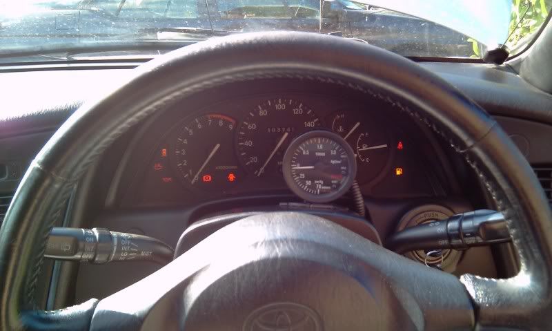
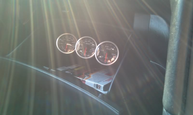
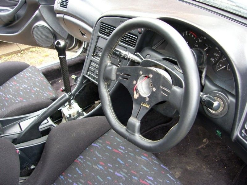
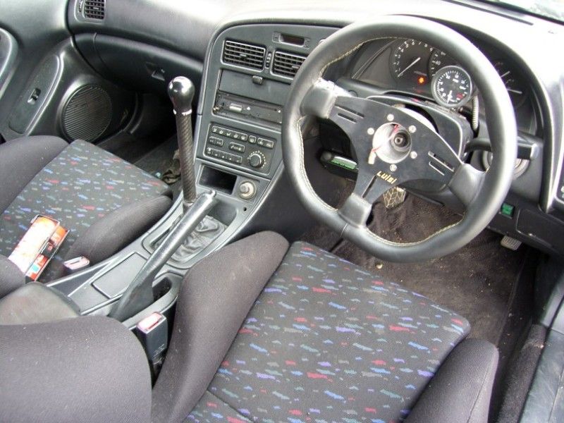
First of all the last of the items from 2011, I spent a bit of time re-organising the dash and numerous gauges. Initially the defi oil temp / oil pressure / water temp and the omori stepper boost gauges were mounted to the left of the binnacle on top of the dash, in full view of any unsavoury characters and also obstructing my view out.
I moved the boost gauge so that it sat on the column cowl, this was neat and tidy and only obstructed the stock boost gauge and the bottom of the rev counter.
The defi gauges were moved into the glove box, they can be easily seen if required, but also closed away when not needed.
Just after this it was my birthday, I took the day off and my wife and I took our other toy out to stretch it’s legs. It was the last warm day of the year and a week day, the track was so quiet, we were sharing it with two other karts all day, immense fun for £30!


Here is my build thread for the kart if anyone is interested -
http://www.karting1.co.uk/forum/viewtopic.php?t=72...
The BC coilovers arrived and the strip down could commence, the car came with C-One coilovers which I am sure, were excellent when new, however the are now tired and in need of replacement. The rears were easy to remove, fronts less so! The tapered joints took a hell of a lot of ‘caressing’ with a big hammer to remove, once off they were treated to a nice new hacksaw blade and the superslut lower parted from the C-One uppers.
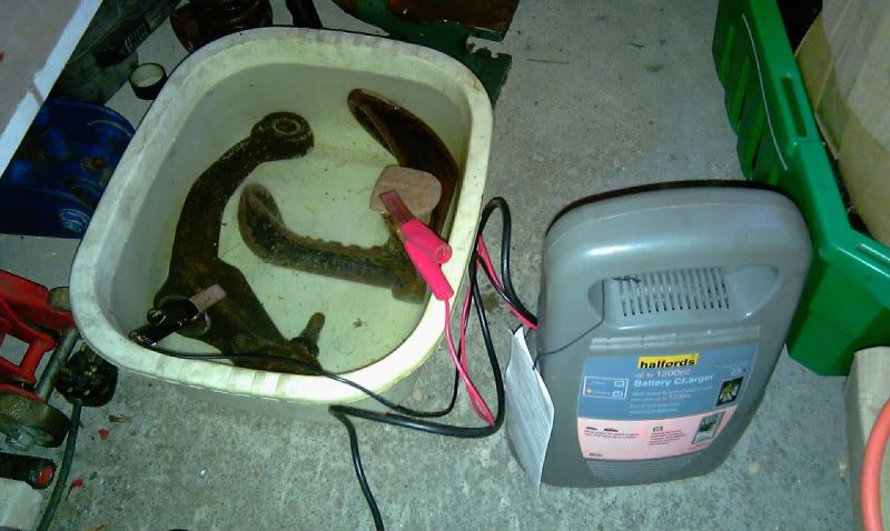
The lowers were well corroded after years of sitting under a rally weapon, this gave me a chance to have a go at electrolysis to remove the oxidised surface.
I used an electrolyte made from bicarbonate of soda and water, the power source was a battery charger, and the cathode a large lump of cast iron. Once connected up it was just a case of time.
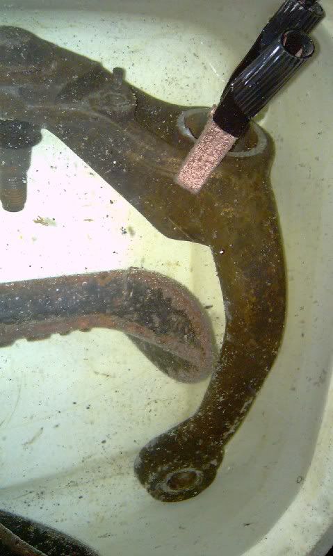
After a few hours each, the lower legs were in pretty good shape, a bit of a scrub to remove some loose bits and they were ready for welding to the BC lower adjustable legs. At this point I decided to remove a couple of sharp edges with the die grinder, this then turned into a marathon session to remove all the forging marks and remove any stress raisers! Once they were prepped the TIG was busted out for welding action, some parts were pretty hard to access but the final result was acceptable and should be durable.
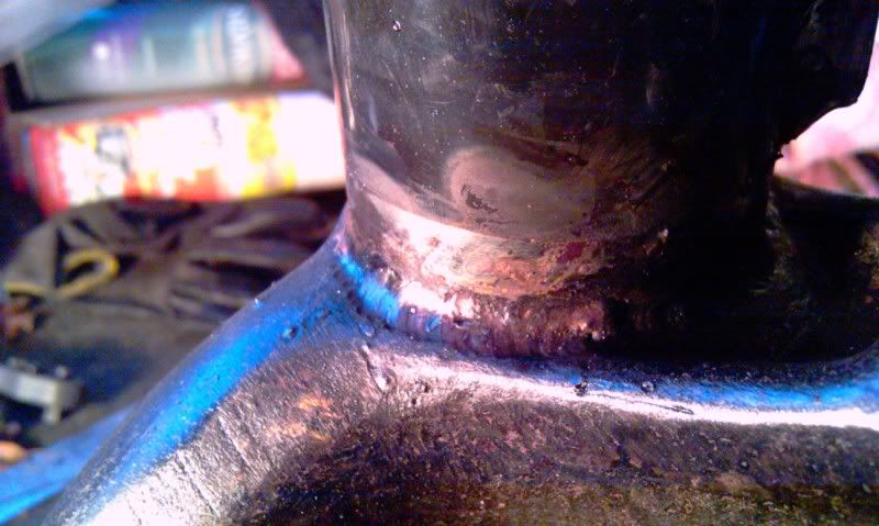
Once welded the legs were coated in a pre-paint surface preparation solution, etch primed and given a coat of gloss black.
Once the paint had flashed off I used a pair of dividers to scribe a line around Fig8 mounting point, having paint under a bolted joint is a really bad thing. Once torqued up the paint will creep out resulting in the tension backing off and the joint fretting and possibly failing. This scribed line allowed the paint to be removed in a neat fashion around the bolted area and the joint to remain intact.
Both front and rear units were then built up copious amounts of grease to prevent corrosion, the front units fitted with new ball joints, and then fitted to the car.
Old ones off, new ones on!
At this point all of the brakes have been removed, the old perished lines are being sent to a hose specialist to be re-manufactured with stainless braided hose, but still using all of the original mounting points to prevent the fatigue that has plagued most aftermarket braided hoses. The callipers are all in good shape and have been given a hot de-grease ready for paint.
Once the hoses have arrived the brake system can be rebuilt, rear spacers fitted and the car can go back on it’s wheels! Then it is a new clutch plate and I can start driving it
Thanks for reading.
J
Right, finally time for another update! Been a busy couple of months with interviews for new jobs, Christmas etc etc, the result being the Celica coming bottom of the list
Now in the new year things are settling down, I have got the job I wanted and am waiting for the contract to arrive, the house is nearly finished ready to go on the market, and the Celica is finally getting closer to being back on it’s wheels.
First of all the last of the items from 2011, I spent a bit of time re-organising the dash and numerous gauges. Initially the defi oil temp / oil pressure / water temp and the omori stepper boost gauges were mounted to the left of the binnacle on top of the dash, in full view of any unsavoury characters and also obstructing my view out.
I moved the boost gauge so that it sat on the column cowl, this was neat and tidy and only obstructed the stock boost gauge and the bottom of the rev counter.
The defi gauges were moved into the glove box, they can be easily seen if required, but also closed away when not needed.
Just after this it was my birthday, I took the day off and my wife and I took our other toy out to stretch it’s legs. It was the last warm day of the year and a week day, the track was so quiet, we were sharing it with two other karts all day, immense fun for £30!
Here is my build thread for the kart if anyone is interested -
http://www.karting1.co.uk/forum/viewtopic.php?t=72...
The BC coilovers arrived and the strip down could commence, the car came with C-One coilovers which I am sure, were excellent when new, however the are now tired and in need of replacement. The rears were easy to remove, fronts less so! The tapered joints took a hell of a lot of ‘caressing’ with a big hammer to remove, once off they were treated to a nice new hacksaw blade and the superslut lower parted from the C-One uppers.
The lowers were well corroded after years of sitting under a rally weapon, this gave me a chance to have a go at electrolysis to remove the oxidised surface.
I used an electrolyte made from bicarbonate of soda and water, the power source was a battery charger, and the cathode a large lump of cast iron. Once connected up it was just a case of time.
After a few hours each, the lower legs were in pretty good shape, a bit of a scrub to remove some loose bits and they were ready for welding to the BC lower adjustable legs. At this point I decided to remove a couple of sharp edges with the die grinder, this then turned into a marathon session to remove all the forging marks and remove any stress raisers! Once they were prepped the TIG was busted out for welding action, some parts were pretty hard to access but the final result was acceptable and should be durable.
Once welded the legs were coated in a pre-paint surface preparation solution, etch primed and given a coat of gloss black.
Once the paint had flashed off I used a pair of dividers to scribe a line around Fig8 mounting point, having paint under a bolted joint is a really bad thing. Once torqued up the paint will creep out resulting in the tension backing off and the joint fretting and possibly failing. This scribed line allowed the paint to be removed in a neat fashion around the bolted area and the joint to remain intact.
Both front and rear units were then built up copious amounts of grease to prevent corrosion, the front units fitted with new ball joints, and then fitted to the car.
Old ones off, new ones on!
At this point all of the brakes have been removed, the old perished lines are being sent to a hose specialist to be re-manufactured with stainless braided hose, but still using all of the original mounting points to prevent the fatigue that has plagued most aftermarket braided hoses. The callipers are all in good shape and have been given a hot de-grease ready for paint.
Once the hoses have arrived the brake system can be rebuilt, rear spacers fitted and the car can go back on it’s wheels! Then it is a new clutch plate and I can start driving it
Thanks for reading.
J
Feb 25th 2012
Bit of an update, shes back on her wheels!
Todays tasks were -
swap rear calipers side to side (felt proper special, bleed nipples go at the top, not the bottom!)
fit final clip to brake line
bleed brakes
check all nuts / bolts and fit split pins
wheels back on and back on the ground
pop up and down the road to see how she feels!
Well the caliper swap was an easy five minutes, just felt a bit silly thats all!
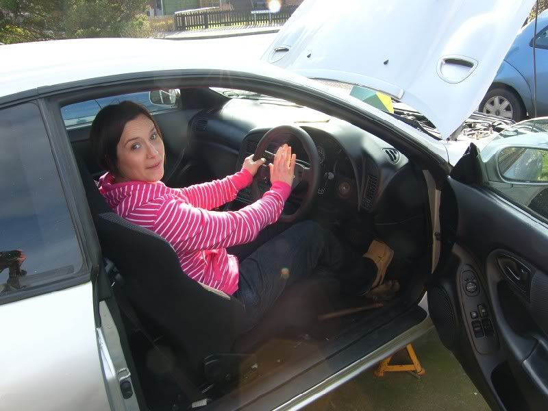
Next up I had help from the very understanding other half -
And the woof -

She was on the pedals and doing a sterling job, down...up....down....up....down (steady on back there!), dog sat in the sunshine overseeing all
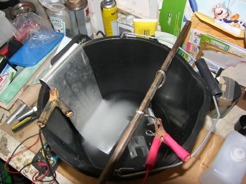
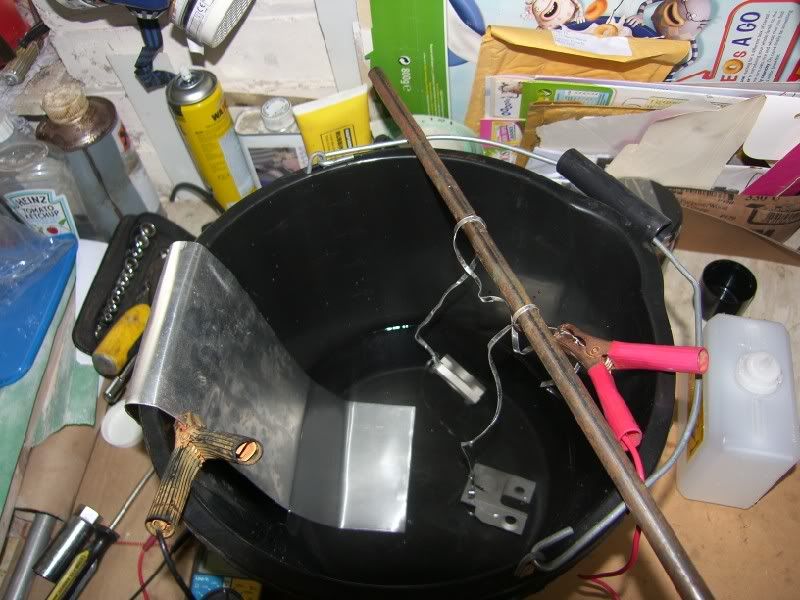
I was on the calipers with this little rig -
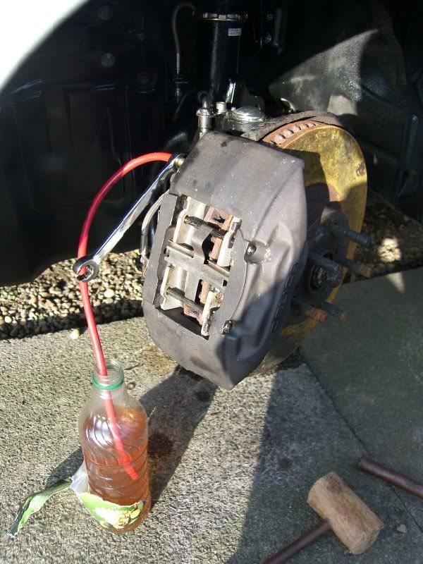
As long as the pipe is in the fluid, it bleeds perfectly!
After putting a whole litre of Toyota fluid in there, we have an acceptable pedal, still think there is some air hiding in there, might work its own way out via gravity over the coming idle time on the drive?
Then it was wheels on and a pop round the block -
Click V

Click ^
I tell you what, the Cusco plate LSD scared the life out of me, I had no idea it was going to clonk like it does on tight turns, DUNKDUNKDUNKDUNK. I pulled off the drive slowly and promptly reversed it back again, then got out to check for wheels catching coilovers arches etc etc! No sign of any perverse rubbing, so a quick drive up and down the road shows everything is well.
Next up it will be raised by about an inch, its waaay too low at the moment, catches when steering etc. Then I need to think about clutch and getting the geometry sorted out fun times!
Bit of an update, shes back on her wheels!
Todays tasks were -
swap rear calipers side to side (felt proper special, bleed nipples go at the top, not the bottom!)
fit final clip to brake line
bleed brakes
check all nuts / bolts and fit split pins
wheels back on and back on the ground
pop up and down the road to see how she feels!
Well the caliper swap was an easy five minutes, just felt a bit silly thats all!
Next up I had help from the very understanding other half -
And the woof -
She was on the pedals and doing a sterling job, down...up....down....up....down (steady on back there!), dog sat in the sunshine overseeing all
I was on the calipers with this little rig -
As long as the pipe is in the fluid, it bleeds perfectly!
After putting a whole litre of Toyota fluid in there, we have an acceptable pedal, still think there is some air hiding in there, might work its own way out via gravity over the coming idle time on the drive?
Then it was wheels on and a pop round the block -
Click V
Click ^
I tell you what, the Cusco plate LSD scared the life out of me, I had no idea it was going to clonk like it does on tight turns, DUNKDUNKDUNKDUNK. I pulled off the drive slowly and promptly reversed it back again, then got out to check for wheels catching coilovers arches etc etc! No sign of any perverse rubbing, so a quick drive up and down the road shows everything is well.
Next up it will be raised by about an inch, its waaay too low at the moment, catches when steering etc. Then I need to think about clutch and getting the geometry sorted out
fun times!May 7th 2012
Finally time for another update, F1 has officially taken over my life!
I found out 24 hours before take off that we were not going to the Mugello test, leaving a whole long weekend open to seeing wife / friends / tinkering with cars!
I took the Celica to the garage to get it MOT’d ready to drive to the other garage that was going to remove the engine and swap the clutch for me. Well that was the plan, what actually happened was a bit more protracted and troublesome. The clutch that was slipping totally gave out ¾’s of the way to the MOT garage, this left me doing 20mph trying to modulate the torque and keep the car moving.
It failed it’s MOT on wipers and that’s it (I was going to visit Halfords to fit new ones, that went out the window the the clutch!), so the next problem was how to move a car with no clutch? This is where Gem Motoring Assist come in with a flat bed
The car was shipped to TR&D near Nottingham and the removal process started, by the end of Thursday the engine was out and ready for me to collect the clutch and deliver it to C.G.Motorsport in Leeds.
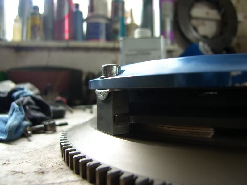
The pinion of the bevel drive is enormous! Compare it’s size to the 3” dump pipe next to it
The clutch prior to removal
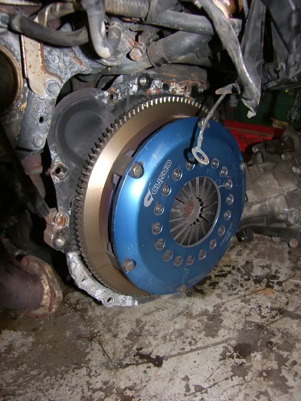
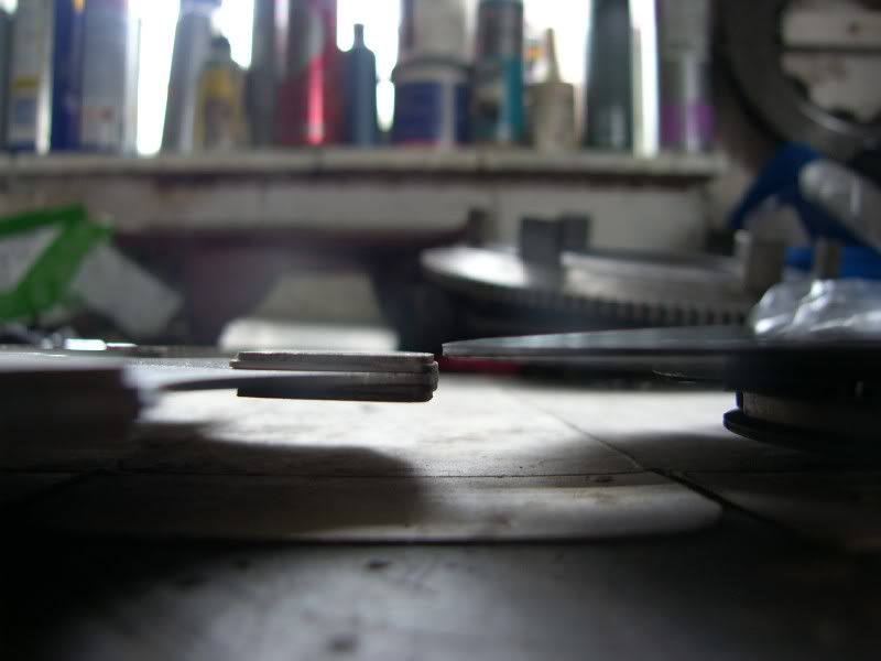
Upon further investigation it is good that I decided against replacing the plate. When the clutch as been slipping under power, there has been a big heat build up, this had coned both the floating plate and flywheel face by about 1mm each.
Fortunately the process that CG Motorsport were proposing would remove this coning and provide a more suitable plate for road use.
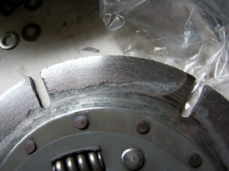
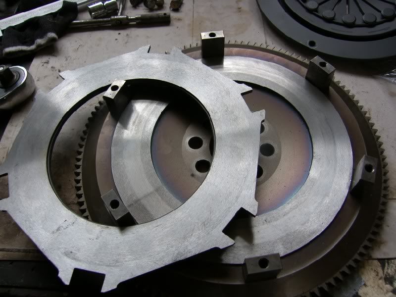
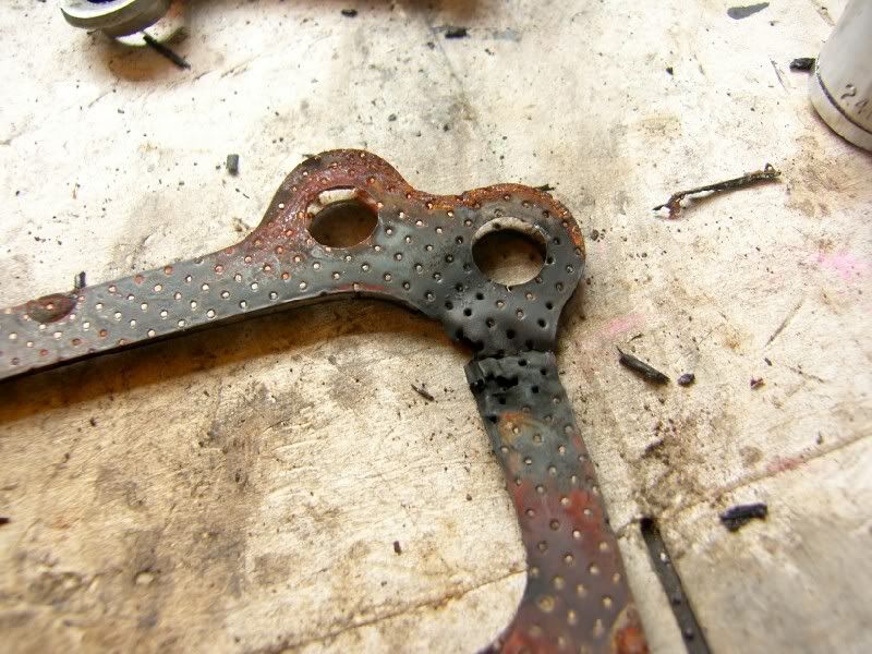
You can see from this picture, the wear across the plate is uneven, with the outer edge completely worn down to the steel of the plate. The springs were also deformed and loose.
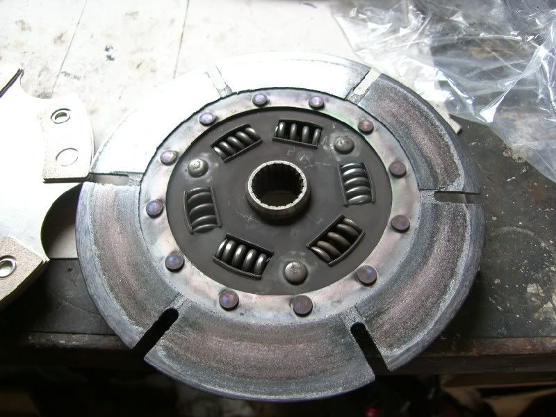
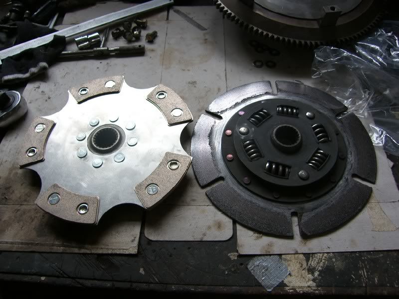
The replacement plate has a more durable solid center plate, and is a cerametallic puck type, these have much higher heat capacity that the sintered plate.
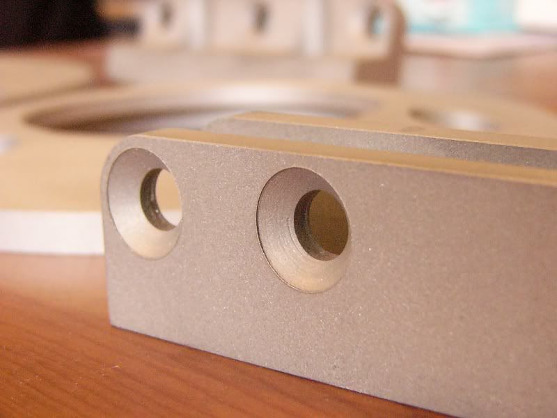
To accommodate the thicker plate the surfaces were ground down, making further room, there was not quite enough meat to fit it in, so the cover was spaced using washers. I was not happy with this solution due to the increased pressure on the aluminium.
You can see some of the deformation here –
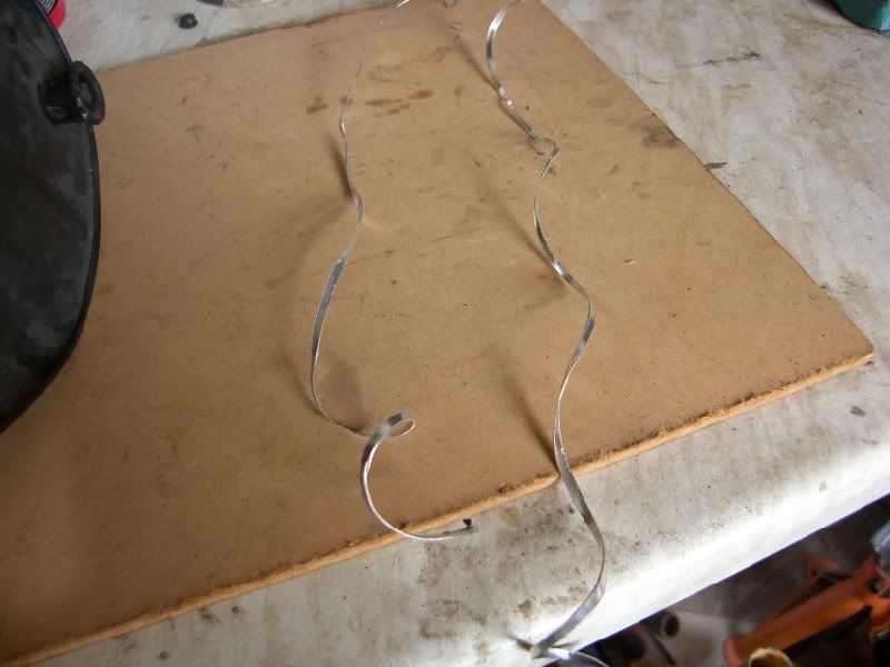
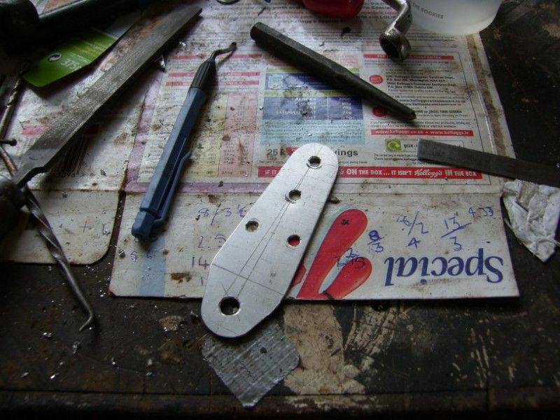
Initially I came up with using some stainless sheet to make some spacers that would have the same surface area are the original support posts.
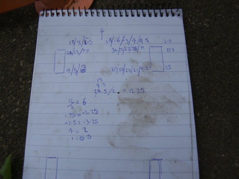
I made a cardboard template to try the theory –
Marked it out –
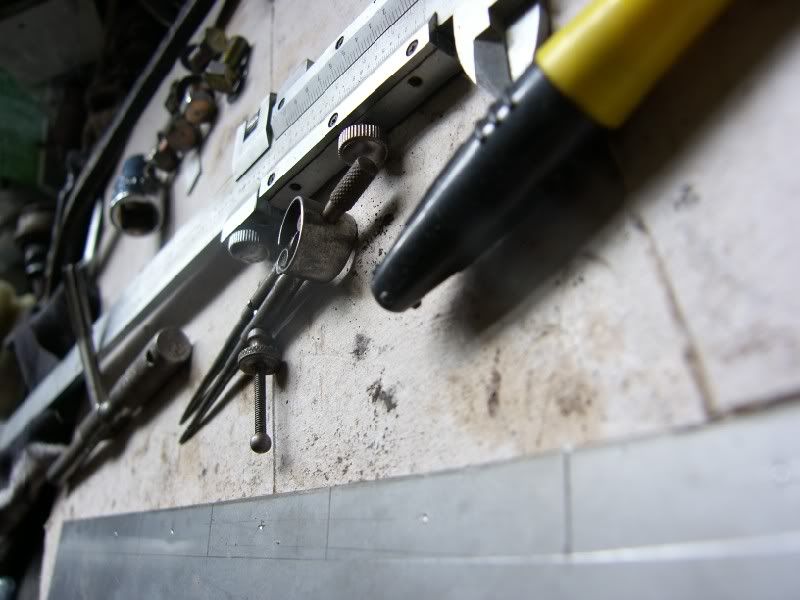
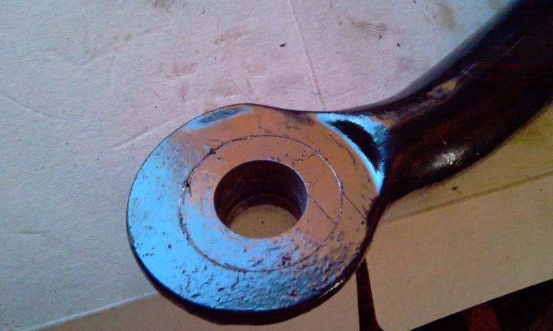
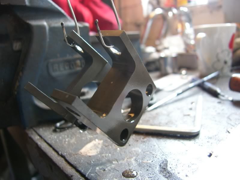
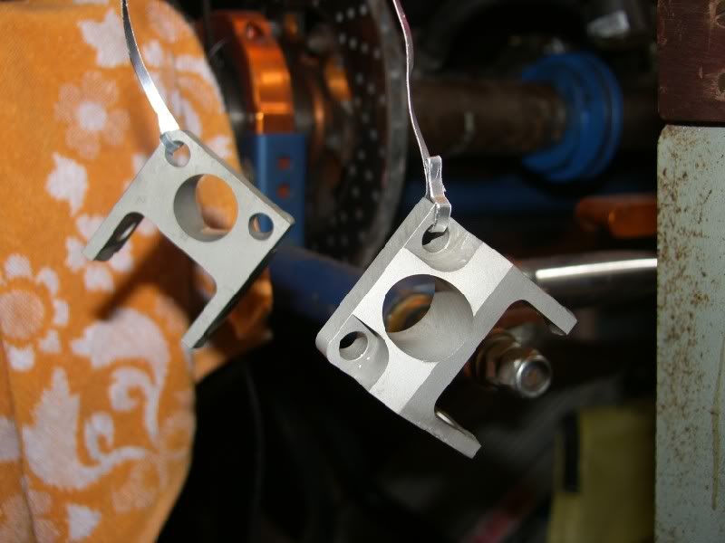
Once drilled / cut / filed / and folded, the first one was tried for size –
As you can see the stainless was very hard to keep flat around the drilled area, resulting in deformation. This was not viable and so another solution had to be investigated.
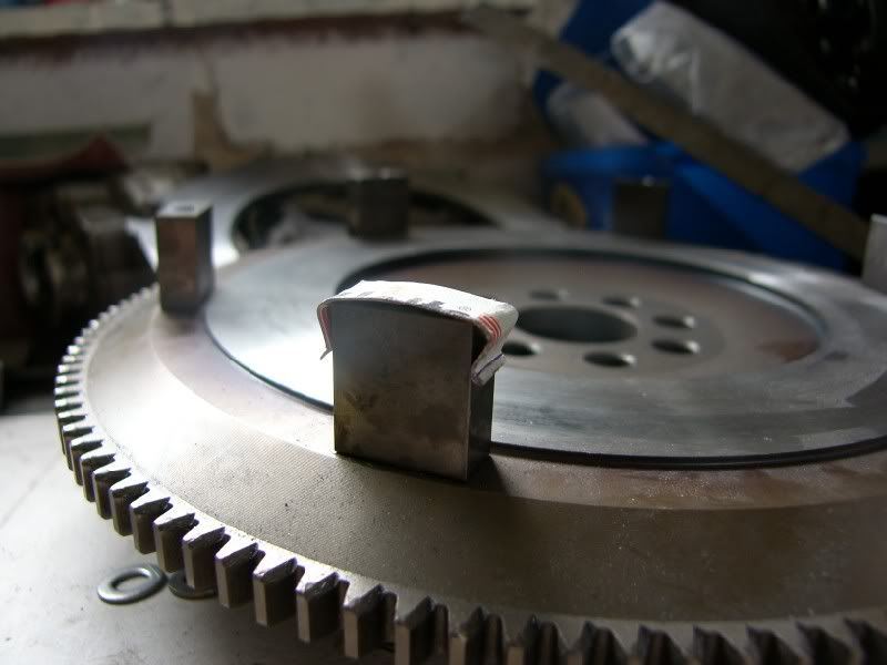
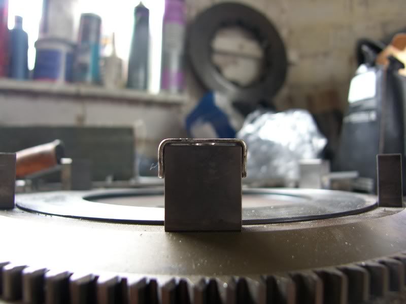
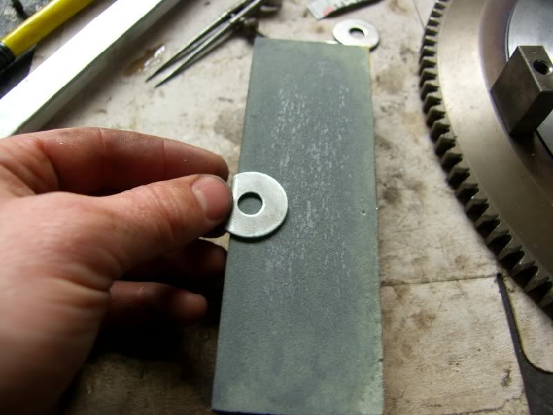
After some thought, I was looking at some penny washers, these would give a very similar surface area to the original fitting, they could be ground to match the thickness of the washers supplied and tested by CG motorsport, and I had 6 of them!
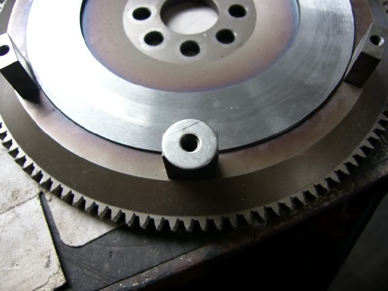
You can see here the difference in area between the penny washer and the supplied items –
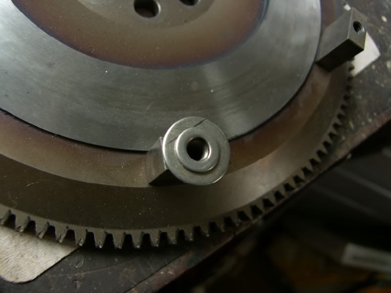
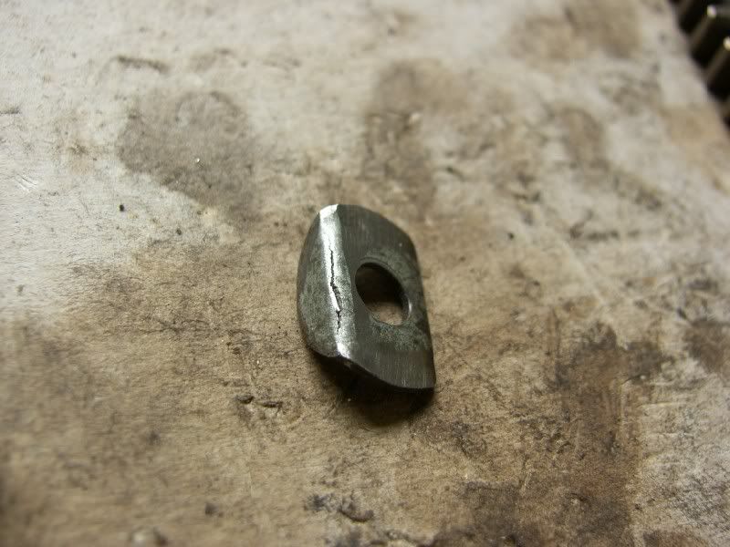
I folded the edge to provide an anti rotation feature, and reduce the width of them, ground the surfaces flat and check thickness between them.
I found that one of them had cracked when folding so this one was replaced with another one –
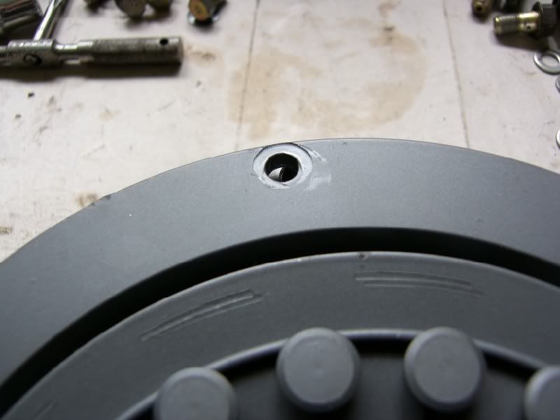
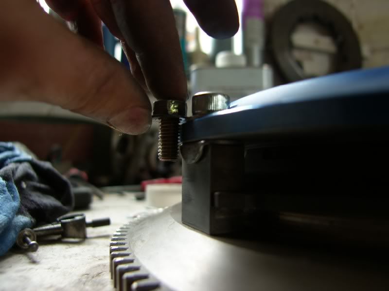
I also took the opportunity to replace the cover bolts with 12.9 allen head items with a longer thread engagement –
Original –
Replacement –
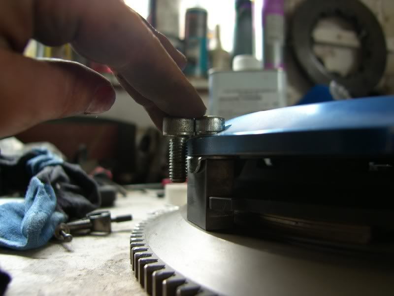
And the final joint looks like this –
Overall I am much happier with this as a spacing solution, It maintains the original design specifications without any sacrifices.
Tomorrow we will be delivering it back to TR&D ready to be fitted, the only other item that needs sorting out is the release bearing, as the one that was in there was totaled!
Speak soon chaps.
J
Finally time for another update, F1 has officially taken over my life!
I found out 24 hours before take off that we were not going to the Mugello test, leaving a whole long weekend open to seeing wife / friends / tinkering with cars!
I took the Celica to the garage to get it MOT’d ready to drive to the other garage that was going to remove the engine and swap the clutch for me. Well that was the plan, what actually happened was a bit more protracted and troublesome. The clutch that was slipping totally gave out ¾’s of the way to the MOT garage, this left me doing 20mph trying to modulate the torque and keep the car moving.
It failed it’s MOT on wipers and that’s it (I was going to visit Halfords to fit new ones, that went out the window the the clutch!), so the next problem was how to move a car with no clutch? This is where Gem Motoring Assist come in with a flat bed
The car was shipped to TR&D near Nottingham and the removal process started, by the end of Thursday the engine was out and ready for me to collect the clutch and deliver it to C.G.Motorsport in Leeds.
The pinion of the bevel drive is enormous! Compare it’s size to the 3” dump pipe next to it
The clutch prior to removal
Upon further investigation it is good that I decided against replacing the plate. When the clutch as been slipping under power, there has been a big heat build up, this had coned both the floating plate and flywheel face by about 1mm each.
Fortunately the process that CG Motorsport were proposing would remove this coning and provide a more suitable plate for road use.
You can see from this picture, the wear across the plate is uneven, with the outer edge completely worn down to the steel of the plate. The springs were also deformed and loose.
The replacement plate has a more durable solid center plate, and is a cerametallic puck type, these have much higher heat capacity that the sintered plate.
To accommodate the thicker plate the surfaces were ground down, making further room, there was not quite enough meat to fit it in, so the cover was spaced using washers. I was not happy with this solution due to the increased pressure on the aluminium.
You can see some of the deformation here –
Initially I came up with using some stainless sheet to make some spacers that would have the same surface area are the original support posts.
I made a cardboard template to try the theory –
Marked it out –
Once drilled / cut / filed / and folded, the first one was tried for size –
As you can see the stainless was very hard to keep flat around the drilled area, resulting in deformation. This was not viable and so another solution had to be investigated.
After some thought, I was looking at some penny washers, these would give a very similar surface area to the original fitting, they could be ground to match the thickness of the washers supplied and tested by CG motorsport, and I had 6 of them!
You can see here the difference in area between the penny washer and the supplied items –
I folded the edge to provide an anti rotation feature, and reduce the width of them, ground the surfaces flat and check thickness between them.
I found that one of them had cracked when folding so this one was replaced with another one –
I also took the opportunity to replace the cover bolts with 12.9 allen head items with a longer thread engagement –
Original –
Replacement –
And the final joint looks like this –
Overall I am much happier with this as a spacing solution, It maintains the original design specifications without any sacrifices.
Tomorrow we will be delivering it back to TR&D ready to be fitted, the only other item that needs sorting out is the release bearing, as the one that was in there was totaled!
Speak soon chaps.
J
June 7th 2012
Well since the last update, I have finally driven the car! It was a voyage of discovery, as I have not driven the car since the day I bought it, so the first drive was to find out if anything else was wrong that I had not identified.
Whilst I was away on my last trip, Michelle my wife picked up the car from the garage for me, a trip that involved 2 buses, 2 trains and a taxi! Wonderful wife
When I got back I could finally drive it, and the result was overall very good. The suspension was brilliant, well damped with good control, stiff enough to not roll but compliant enough to not be jarring. I would compare the ride to my E39 535i sport, just a little stiffer.
The brakes are amazing, I warmed the tyres up, checked for traffic and decided to bed the pads in. The first stop was very good, the second made me feel nauseous! The braking power is incredible!
The engine is strong and has no real issues except for needing more boost
The drive train does have some issues, I am unsure how much of it comes from the fact the diff is very tight and how much come from wear, the symptoms are whining / grinding on overrun and heavy vibration on low RPM wide open throttle acceleration.
I took the decision to remove the diff and inspect the bearings and gear setup.
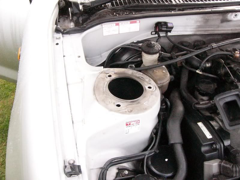
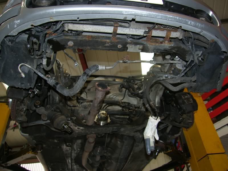
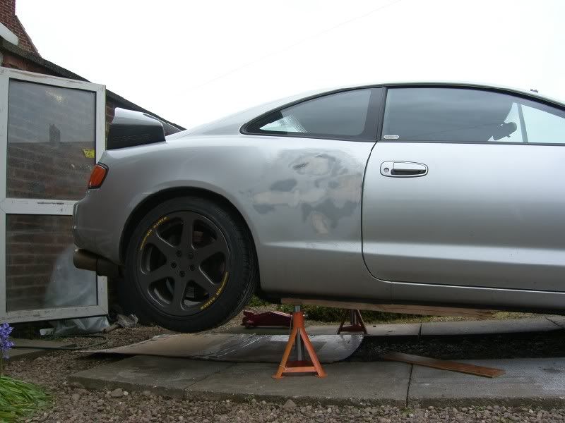
Car in the air –
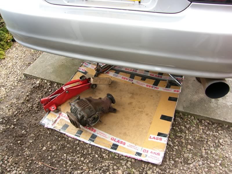
Diff out –
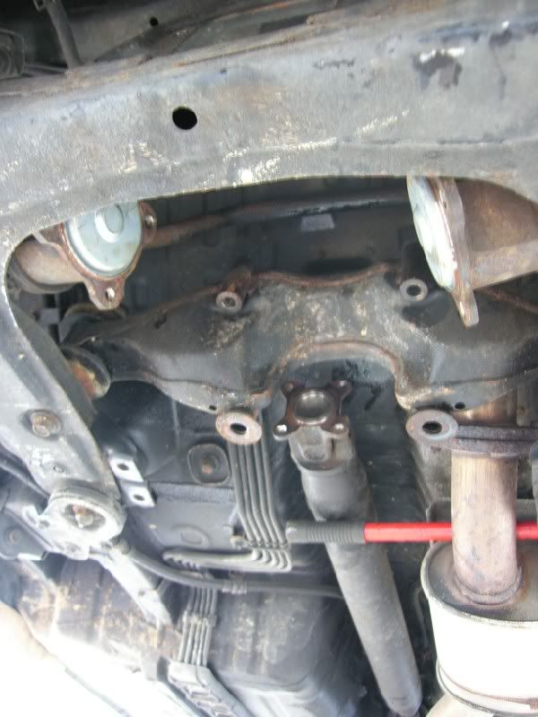
Hole left! –
This is an excerpt from my investigation -
I have done some more investigation, the diff is out and I have cleaned the crown wheel and pinion. This is what I have learnt so far -

Ring Gear Tooth Nomenclature
A – Top. The top of the gear tooth, a.k.a. Face, Top Land
B – Root. The bottom of the gear tooth, a.k.a. Flank
C – Heel. The outside-diameter-end of the gear tooth
D – Toe. The inside-diameter-end of the gear tooth
E – Coast. The concave side of the gear tooth*
F – Drive. The convex side of the gear tooth*
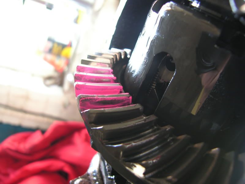
I used a paint pen on the teeth and then ran the gears round under a bit of load.
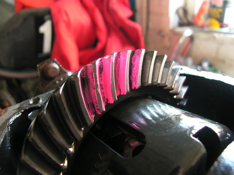
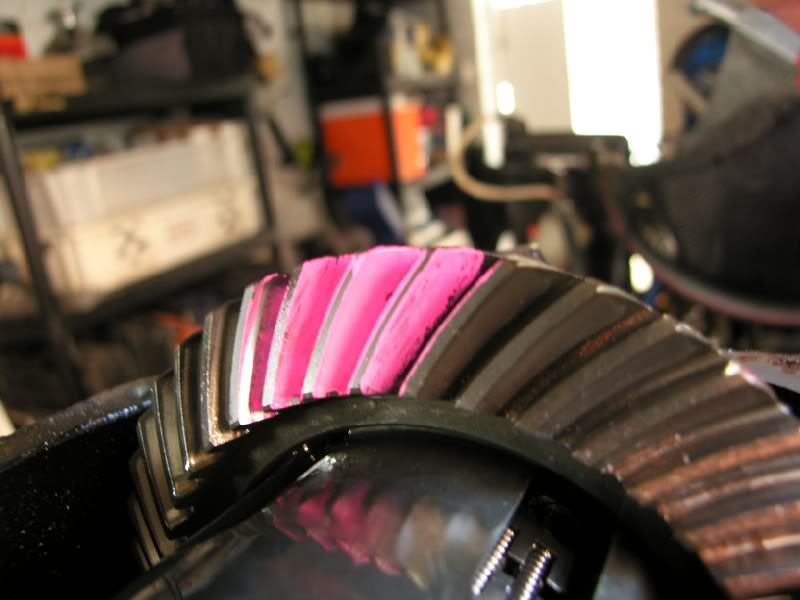
So this is what the contact pattern looks like on mine, sorry about the photos, it is really hard to get a picture of the marks left!
'coast' side -
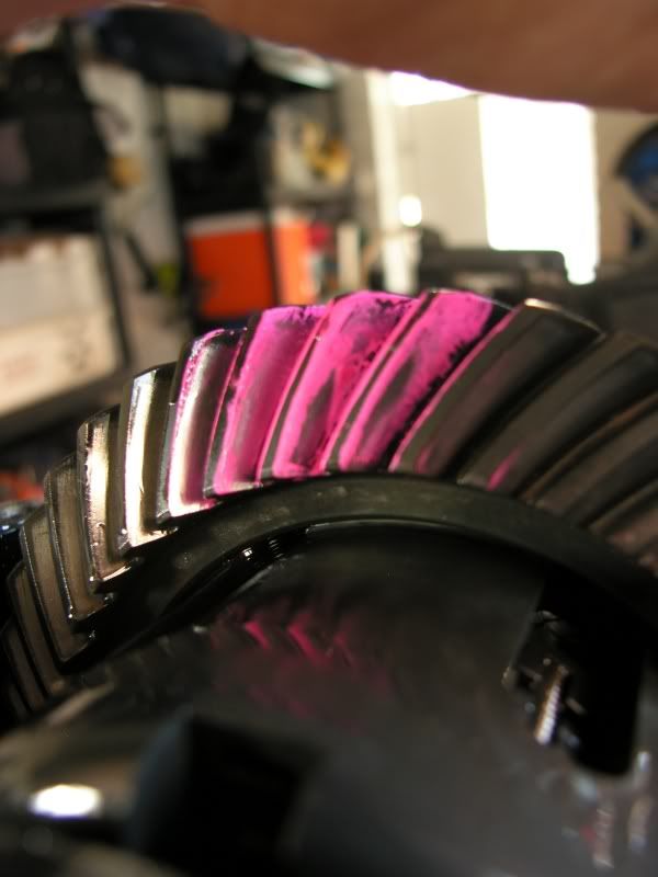
'drive' side -
toyota manual says -
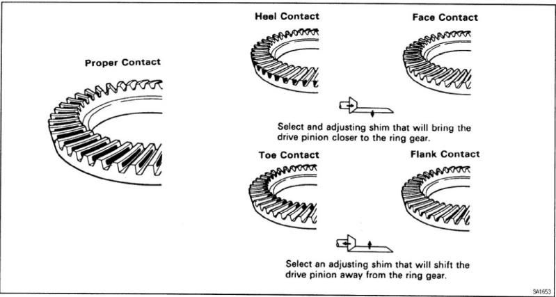
Differentials.com says -

So from what I can see, I am between the bottom two images, maybe slightly too much backlash? I have dial gauge on order so I can measure that, I will update when I get back from Monaco :?
So at this point, I have arrived back from Monaco and I can continue the investigation, I put the dial gauge on the case and measured the crown wheel backlash –
Zeroed out -
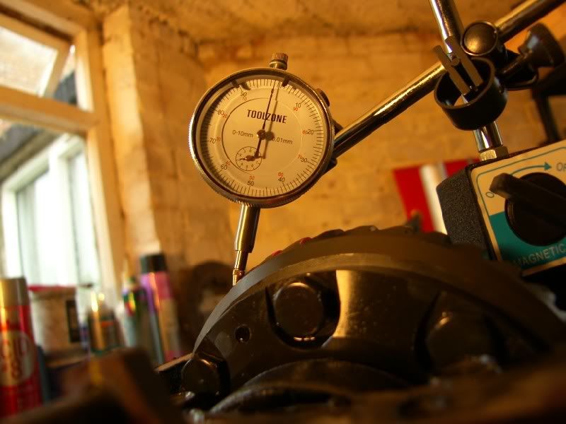
Rocked back and forth –
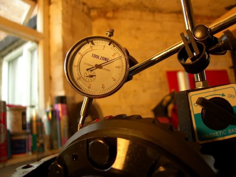
So that makes 130 microns, bang on the Toyota set up figure. So I there is nothing wrong with the diff or set up :S
I think that the noises on overrun are to do with the very tight 2 way LSD, having no experience of it it is kinda hard to tell.
The prop was inspected whilst everything was off, the support bearings were fine, CV feels fine, the UJ’s have tight points so I think they are on their way out and are staked in so no replacing them!
So I built the diff back up and filled it with 1100cc of Motul EP90 Mineral oil, LSD specific :mrgreen:
Everything was built back up and put back on the ground.
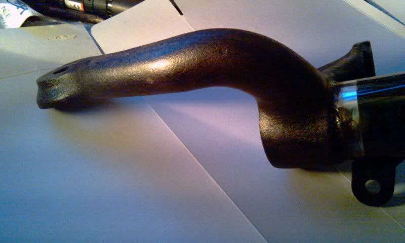
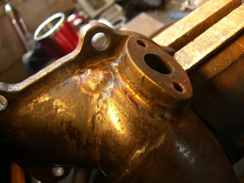
Whilst at the front of the car I noticed a small exhaust leak around the turbo, and then noticed joy of joys a crack on the down pipe!
So I pulled the down pipe off an then found this –
One cooked gasket!
This is the crack on the down pipe –
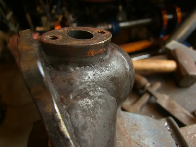
You can see it just below the O2 mount, there is actually a small one just above the lower weld too.
You can clearly see the crack from the inside –
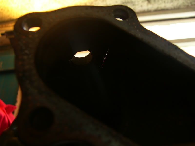
I cleaned it up with the dremel, sealed it off each end using tin foil and back purged it ready to TIG weld –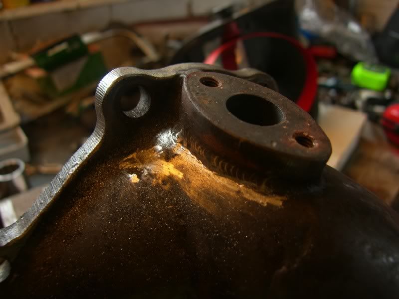
The finished article –
I had to weld a small patch on next to the line that covers the crack, the stainless was very very thin in that area an liable to crack again.
I have fitted it back on the car now and it is working fine, just sealed with exhaust paste atm until the gaskets arrive
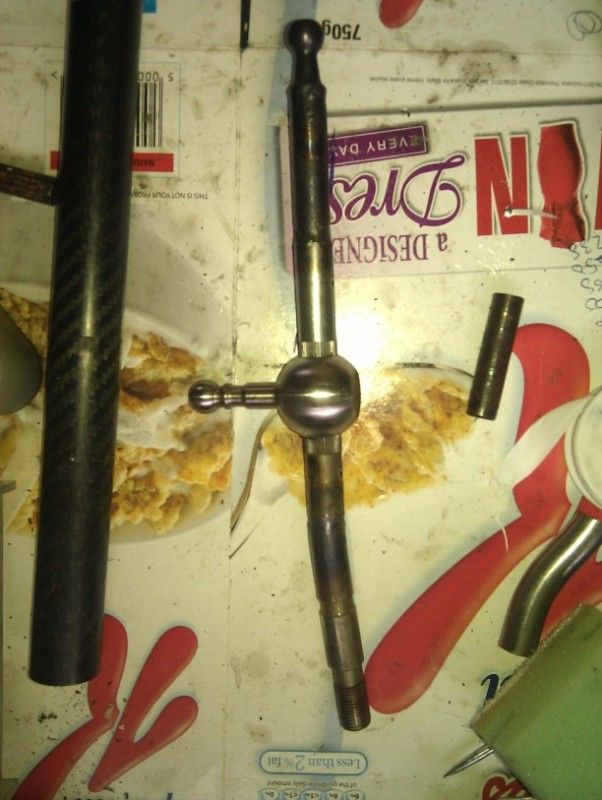
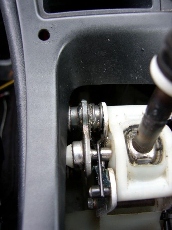
I have been fiddling with the gear shift and mount in the car too, I like to have the gear knob right next to the steering wheel if possible, the celica will be no different. The base mount will be spacered up by 30mm to allow the lower portion of the lever to be extended, then the top will be extended to keep the standard ratio but significantly lengthen the lever.
I was unsure what to lengthen the lever with, then upon inspection I found that the TRD shift knob has a straight bored hole in the bottom…..I wonder…..
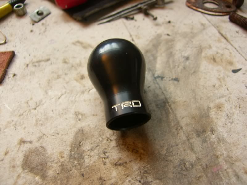
Hmmmmm, carbon or titanium????
Apart from that, I have tidied up a lot of the wiring under the bonnet, removing the horn wiring and relays that were added at some point, only after investigating and finding that they were running a relay and fuse to run another relay and fuse!
I have also tidied up a lot of the vacuum hosing and simplified the routing
Ok enough for now, I think I am going to enjoy driving it for a while
J
Well since the last update, I have finally driven the car! It was a voyage of discovery, as I have not driven the car since the day I bought it, so the first drive was to find out if anything else was wrong that I had not identified.
Whilst I was away on my last trip, Michelle my wife picked up the car from the garage for me, a trip that involved 2 buses, 2 trains and a taxi! Wonderful wife
When I got back I could finally drive it, and the result was overall very good. The suspension was brilliant, well damped with good control, stiff enough to not roll but compliant enough to not be jarring. I would compare the ride to my E39 535i sport, just a little stiffer.
The brakes are amazing, I warmed the tyres up, checked for traffic and decided to bed the pads in. The first stop was very good, the second made me feel nauseous! The braking power is incredible!
The engine is strong and has no real issues except for needing more boost
The drive train does have some issues, I am unsure how much of it comes from the fact the diff is very tight and how much come from wear, the symptoms are whining / grinding on overrun and heavy vibration on low RPM wide open throttle acceleration.
I took the decision to remove the diff and inspect the bearings and gear setup.
Car in the air –
Diff out –
Hole left! –
This is an excerpt from my investigation -
I have done some more investigation, the diff is out and I have cleaned the crown wheel and pinion. This is what I have learnt so far -
Ring Gear Tooth Nomenclature
A – Top. The top of the gear tooth, a.k.a. Face, Top Land
B – Root. The bottom of the gear tooth, a.k.a. Flank
C – Heel. The outside-diameter-end of the gear tooth
D – Toe. The inside-diameter-end of the gear tooth
E – Coast. The concave side of the gear tooth*
F – Drive. The convex side of the gear tooth*
- Don’t be mislead by the terms “coast” and “drive”, as the ring-gear can be driven by the pinion on either side of the teeth. Which side of the teeth will depend on if the gear-set is standard or reverse spiral and whether the vehicle is going forward or in reverse.
I used a paint pen on the teeth and then ran the gears round under a bit of load.
So this is what the contact pattern looks like on mine, sorry about the photos, it is really hard to get a picture of the marks left!
'coast' side -
'drive' side -
toyota manual says -
Differentials.com says -
So from what I can see, I am between the bottom two images, maybe slightly too much backlash? I have dial gauge on order so I can measure that, I will update when I get back from Monaco :?
So at this point, I have arrived back from Monaco and I can continue the investigation, I put the dial gauge on the case and measured the crown wheel backlash –
Zeroed out -
Rocked back and forth –
So that makes 130 microns, bang on the Toyota set up figure. So I there is nothing wrong with the diff or set up :S
I think that the noises on overrun are to do with the very tight 2 way LSD, having no experience of it it is kinda hard to tell.
The prop was inspected whilst everything was off, the support bearings were fine, CV feels fine, the UJ’s have tight points so I think they are on their way out and are staked in so no replacing them!
So I built the diff back up and filled it with 1100cc of Motul EP90 Mineral oil, LSD specific :mrgreen:
Everything was built back up and put back on the ground.
Whilst at the front of the car I noticed a small exhaust leak around the turbo, and then noticed joy of joys a crack on the down pipe!
So I pulled the down pipe off an then found this –
One cooked gasket!
This is the crack on the down pipe –
You can see it just below the O2 mount, there is actually a small one just above the lower weld too.
You can clearly see the crack from the inside –
I cleaned it up with the dremel, sealed it off each end using tin foil and back purged it ready to TIG weld –
The finished article –
I had to weld a small patch on next to the line that covers the crack, the stainless was very very thin in that area an liable to crack again.
I have fitted it back on the car now and it is working fine, just sealed with exhaust paste atm until the gaskets arrive
I have been fiddling with the gear shift and mount in the car too, I like to have the gear knob right next to the steering wheel if possible, the celica will be no different. The base mount will be spacered up by 30mm to allow the lower portion of the lever to be extended, then the top will be extended to keep the standard ratio but significantly lengthen the lever.
I was unsure what to lengthen the lever with, then upon inspection I found that the TRD shift knob has a straight bored hole in the bottom…..I wonder…..
Hmmmmm, carbon or titanium????
Apart from that, I have tidied up a lot of the wiring under the bonnet, removing the horn wiring and relays that were added at some point, only after investigating and finding that they were running a relay and fuse to run another relay and fuse!
I have also tidied up a lot of the vacuum hosing and simplified the routing
Ok enough for now, I think I am going to enjoy driving it for a while
J
June 16th 2012
Good evening,
Had a fun few days Faffing, been driving the car and enjoying it. I had the front wheels spinning out of a junction earlier today, the rear was locked up hard though, the bloody thing flies!
I have had the down pipe off again, spent some time trying to make the flange a bit flatter, cheap chinese parts are that for a reason! It will work fine after a trip to the fly cutter, however I do not have one of those so my bench belt linisher would have to do. It is a lot better but still not perfect, at least it seals with a gasket now! I also found a few more cracks in the stainless, I call it stainless loosely, the 304 grade used is really poor for exhausts suffering from carbon precipitation at elevated temperatures, hence all the cracks.
Now for the fun bit, I have finally had a go at home anodising 8) It has not gone totally to plan, but the aluminium is well protected now and no one got hurt in the process :thumbsup:
Before I start, some of this stuff is proper nasty, if you decide to have a go yourself, take the right precautions and I can hold no responsibility for your own actions :?
I started out with this kit of bits -
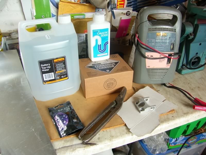
And more importantly these protective items -
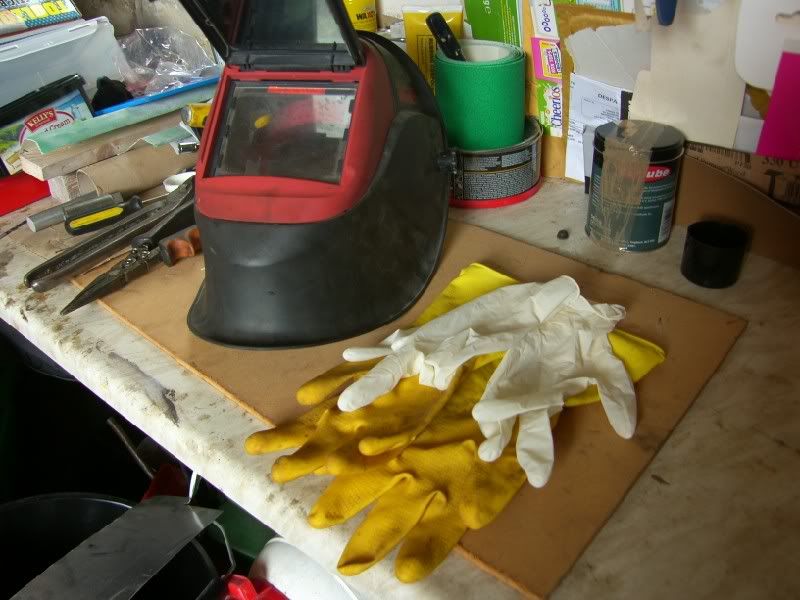
Yep, double bagged on the glove front, handling some of this stuff is pretty scary ops: I was fully protected with synthetic clothing thick enough to protect me, and all skin was covered.
The parts were blasted months ago, and kept in a dry low humidity environment, here they were just after vapour blasting -
They need a proper protective coat, I could paint but i have never been very good at that, chemistry is more my thing
They were attached to a couple of bits of 316l stainless for the de-smut, this cleans the surface of deposits and leaves a perfect surface for the anodising to start on. First things first I donned latex gloves, marigolds, and my welding helmet....... :confuse: I put about 50g of caustic soda into 4l of water, with all these things always add the reactive agent in to the non reactive, in this case, the caustic soda into the water. Two of the parts were then submerged for 15 minutes, fizzing away gently.
While they were cooking away I prepped the rest of the ingredients, two thin strips of ally to hold the parts in the acid -
I put 2000cc of distilled water into a bucket and then prepped the cathode (aluminium sheet) -
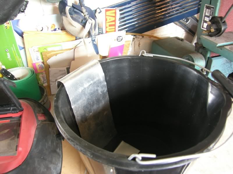
The parts came out of the solution looking like this -
About right, surface successfully etched and ready for the next step, they were washed off with water ready to put into the acid bath, all the way through this process you cannot touch the surface, grease will prevent the process working properly.
I attached the parts securely to the ally strips and then hung them from a piece of steel over the bucket. Once I was happy everything was secure I attached the battery charger to the anode (positive and parts to be anodised) and cathode (negative sacrificial sheet), but not switched on yet.
It was time to start with the battery acid, this was bought from ebay and delivered to my door, incredible! I donned all the safety gear and included a volatile organics mask this time too. Then slowly but surely I added the acid to the water (always add acid AAA!!!!), nothing happened, thankfullyops:
Then it was time to switch on, initially nothing happened, then I realised that the connection between part / strip / steel / positive charger clip was pretty poor, so i moved the clip onto the strips and it all started to work
You can see below, all the gasses fizzing off the cathode, hence the organics mask and lots of windows open, lucky it was a windy day
I then left it to its own devices for 60 minutes, when I came back it looked like this -
The reaction had certainly slowed down somewhat, time to get the parts out. The parts came out a lot brighter but no noticeable change in surface finish?
Now this was an unknown, the dyes recommended were unavailable so some ebay dylon was selected, 90's purple 8)
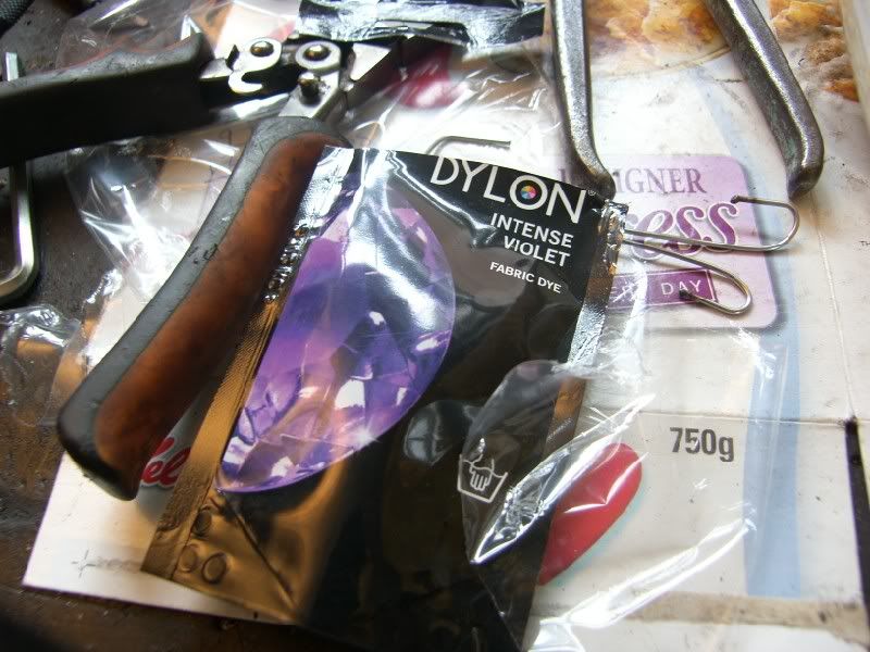
This was mixed into 500ml of hot water and put into a washing up bowl, the bowl was then filled round the outside with boiling water, this would slowly increase the temperature of the dye helping it to take better.
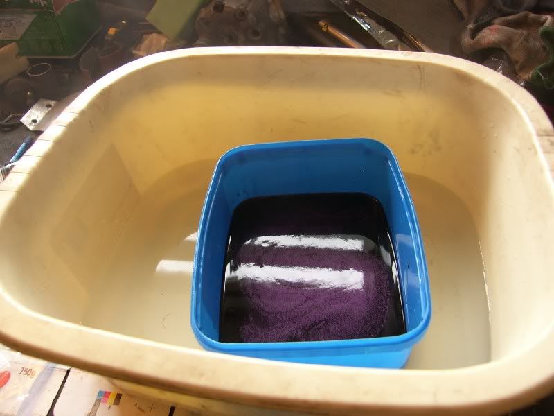
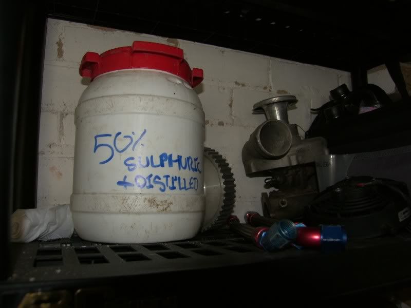
While the dye was taking (I left it for 15 minutes) I stored the acid properly -
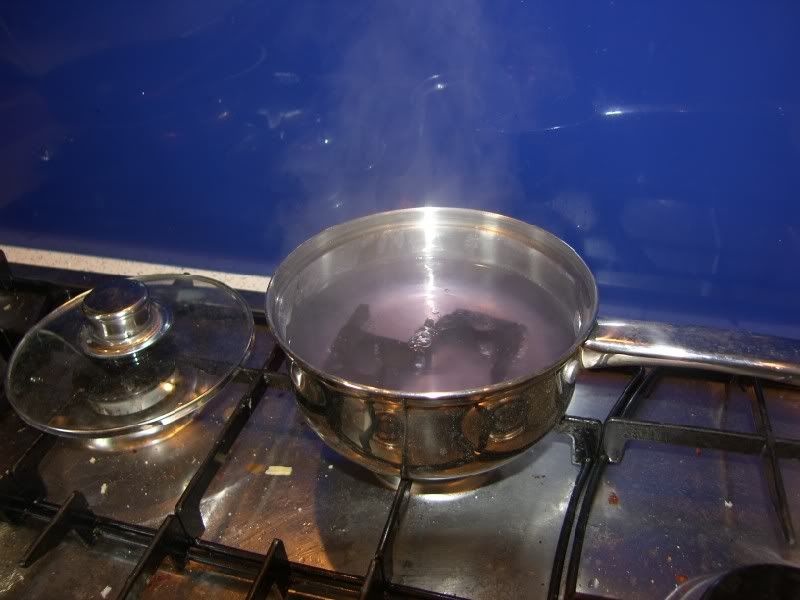
The parts were then taken out of the dye and put straight into a pan of boiling water (thanks wifee ) They were left boiling for 30 minutes and the result was this -
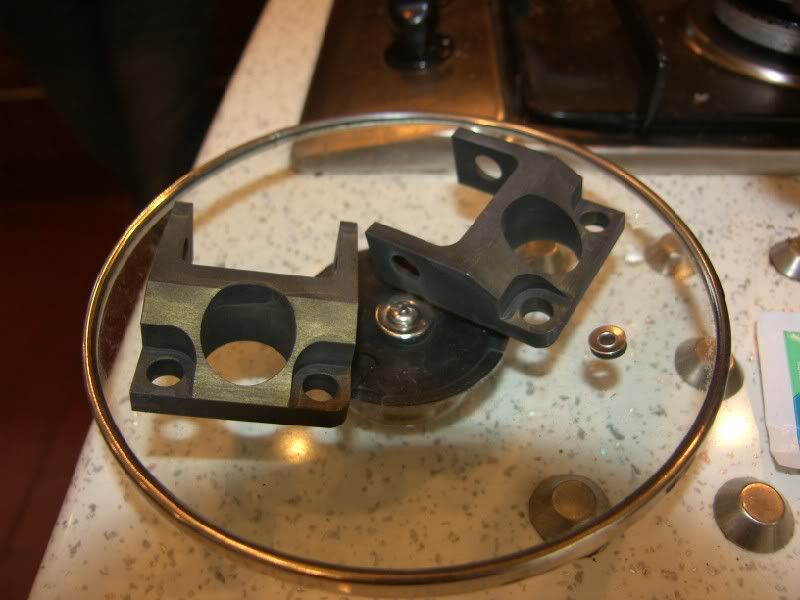
Hmmmm, well I was not aiming for black? :? The anodising has certainly worked, but I think i may have hard anodised rather than normal, hard anodising will only take black and clear colours? Either that or the dye particles are too large in this dye, a common problem?
The question now is, do I strip the anodising and have another go, or just be happy with black parts? :lol:
I won't have any time next week or weekend as I am travelling to Valencia with work, but the week after I am going to have another go, maybe with some new dye? Did multi colour engine bays also go out of fashion in the 90's Looks like we might be heading that way!!!
Hope you are all well, and thanks for looking
J
Good evening,
Had a fun few days Faffing, been driving the car and enjoying it. I had the front wheels spinning out of a junction earlier today, the rear was locked up hard though, the bloody thing flies!
I have had the down pipe off again, spent some time trying to make the flange a bit flatter, cheap chinese parts are that for a reason! It will work fine after a trip to the fly cutter, however I do not have one of those so my bench belt linisher would have to do. It is a lot better but still not perfect, at least it seals with a gasket now! I also found a few more cracks in the stainless, I call it stainless loosely, the 304 grade used is really poor for exhausts suffering from carbon precipitation at elevated temperatures, hence all the cracks.
Now for the fun bit, I have finally had a go at home anodising 8) It has not gone totally to plan, but the aluminium is well protected now and no one got hurt in the process :thumbsup:
Before I start, some of this stuff is proper nasty, if you decide to have a go yourself, take the right precautions and I can hold no responsibility for your own actions :?
I started out with this kit of bits -
And more importantly these protective items -
Yep, double bagged on the glove front, handling some of this stuff is pretty scary
ops: I was fully protected with synthetic clothing thick enough to protect me, and all skin was covered.The parts were blasted months ago, and kept in a dry low humidity environment, here they were just after vapour blasting -
They need a proper protective coat, I could paint but i have never been very good at that, chemistry is more my thing
They were attached to a couple of bits of 316l stainless for the de-smut, this cleans the surface of deposits and leaves a perfect surface for the anodising to start on. First things first I donned latex gloves, marigolds, and my welding helmet....... :confuse: I put about 50g of caustic soda into 4l of water, with all these things always add the reactive agent in to the non reactive, in this case, the caustic soda into the water. Two of the parts were then submerged for 15 minutes, fizzing away gently.
While they were cooking away I prepped the rest of the ingredients, two thin strips of ally to hold the parts in the acid -
I put 2000cc of distilled water into a bucket and then prepped the cathode (aluminium sheet) -
The parts came out of the solution looking like this -
About right, surface successfully etched and ready for the next step, they were washed off with water ready to put into the acid bath, all the way through this process you cannot touch the surface, grease will prevent the process working properly.
I attached the parts securely to the ally strips and then hung them from a piece of steel over the bucket. Once I was happy everything was secure I attached the battery charger to the anode (positive and parts to be anodised) and cathode (negative sacrificial sheet), but not switched on yet.
It was time to start with the battery acid, this was bought from ebay and delivered to my door, incredible! I donned all the safety gear and included a volatile organics mask this time too. Then slowly but surely I added the acid to the water (always add acid AAA!!!!), nothing happened, thankfully
ops: Then it was time to switch on, initially nothing happened, then I realised that the connection between part / strip / steel / positive charger clip was pretty poor, so i moved the clip onto the strips and it all started to work
You can see below, all the gasses fizzing off the cathode, hence the organics mask and lots of windows open, lucky it was a windy day
I then left it to its own devices for 60 minutes, when I came back it looked like this -
The reaction had certainly slowed down somewhat, time to get the parts out. The parts came out a lot brighter but no noticeable change in surface finish?
Now this was an unknown, the dyes recommended were unavailable so some ebay dylon was selected, 90's purple 8)
This was mixed into 500ml of hot water and put into a washing up bowl, the bowl was then filled round the outside with boiling water, this would slowly increase the temperature of the dye helping it to take better.
While the dye was taking (I left it for 15 minutes) I stored the acid properly -
The parts were then taken out of the dye and put straight into a pan of boiling water (thanks wifee
) They were left boiling for 30 minutes and the result was this - Hmmmm, well I was not aiming for black? :? The anodising has certainly worked, but I think i may have hard anodised rather than normal, hard anodising will only take black and clear colours? Either that or the dye particles are too large in this dye, a common problem?
The question now is, do I strip the anodising and have another go, or just be happy with black parts? :lol:
I won't have any time next week or weekend as I am travelling to Valencia with work, but the week after I am going to have another go, maybe with some new dye? Did multi colour engine bays also go out of fashion in the 90's
Looks like we might be heading that way!!!Hope you are all well, and thanks for looking
J
August 7th 2012
I finally have some time off!
After starting at Cosworth F1 I have had no holiday at all, and only about half of the weekends, so progress on the car has been slow up to this point :
So with the start of the FOTA enforced shutdown I have just over 2 weeks off, after visiting friends and family over the weekend it is time to get down to the celica
First of all the aligment had not been done since putting coilovers on the car, with the height change the wheels were pointing in all sorts of directions.
Initially the ride height was upped a little (I know, booooo), it was dragging all over the place and touching wheels to inner arches etc. I went up 30mm at the front and 40mm at the back.
Start point -
Up -
After -
Then the alignment could start, this was the first time I had done a string box alignment, but it is how they set up the F1 cars so it must work, and I have watched it done many times.
I started by getting out 4 axle stands and some string (better with fishing wire, but I don't have any of that!), the front and rear widths were matched, as the alignment is done over the whole axle it would appear that the perpendicularity does not matter?
I then proceeded to measure at the front and back of each tyre to get the toe in / out. It had 12mm (yes!) of toe in!!!!!
After a bit of dicking about i got to 1.5mm of toe in, certainly feels a bit more stable now
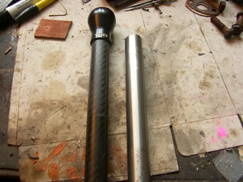
Next up I decided to try and improve the controls, highest on the list was getting the gear lever a little closer to the steering wheel. As per the previous post I had some carbon tube, this was a perfect starting point as an extension to the lever. The issue with doing this was the increase in lever travel was unacceptable.
The solution? A quick shifter.
Problem? Unavailable.
Time to get cutting!
The ratio for the stock lever is 2.54 for both the front to rear bowden cable and side to side bowden cable. I wanted to reduce this slightly to around 2, even when the lever was extended by 200-250mm.
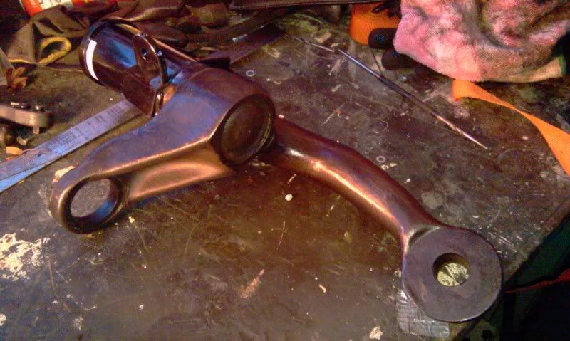
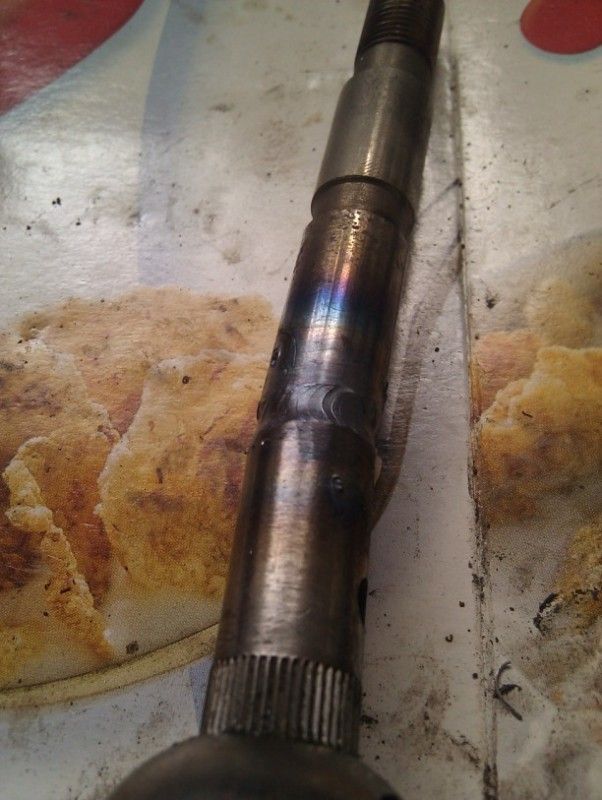
I cut the kink out of the stock lever to get it closer to the driver, then added a section below the pivot to increase the ratio -
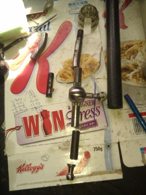
This was then TIG'ed back together -
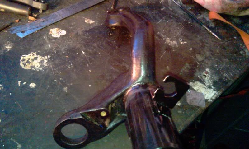
The issue now was that the bottom of the lever was so long it fouled the body! So the pivot needed moving up, after a bit of searching through the scrap bin I found some 3mm plate and a bit of stainless tube. The tube was cut to 45mm and inserted below the socket for the ball. The upper mounting point then needed securing to the lower lever base, a pair of extension brackets were fabricated to fit, not my best work but they do the job intended.
A pair of spacer tubes were fitted to prevent the base collapsing inwards when bolted up.
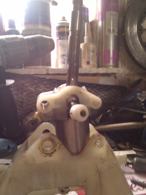
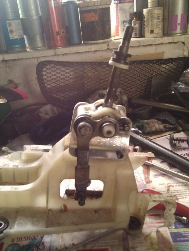
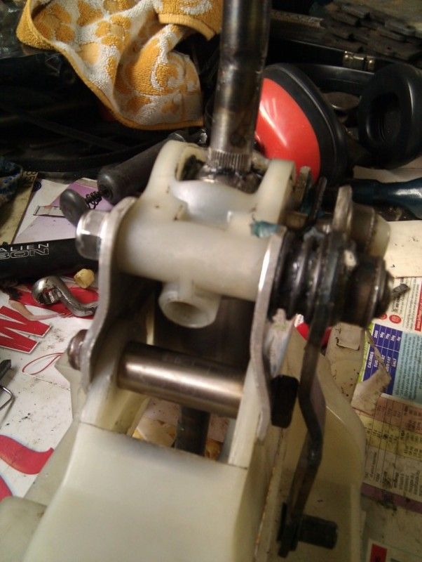
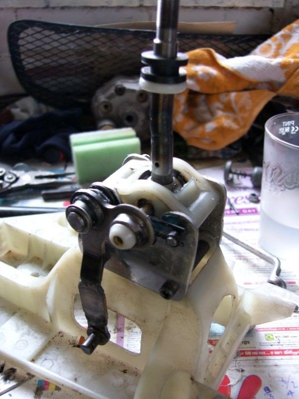
After a bit of clearancing with a dremel (the lever was fouling on the base a little in 1st / 2nd), the unit was finish fitted to the car -
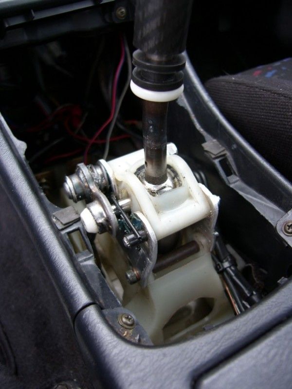
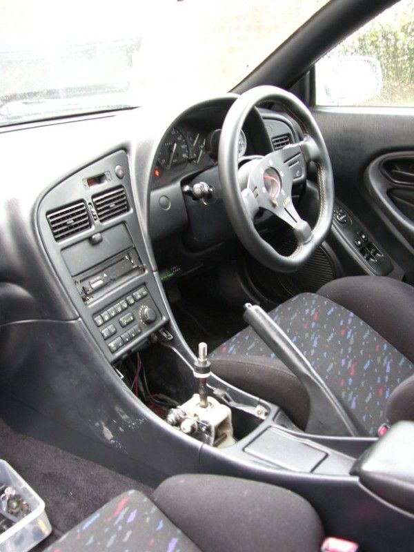
The lever height is not fixed yet, it will take a little bit of adjustment, but I am quite happy with the result, much closer to the steering wheel -
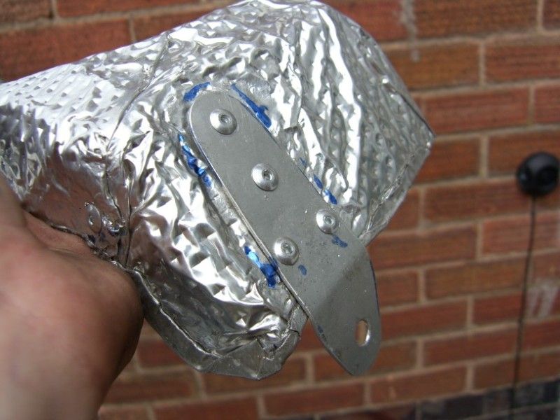
Today, I decided that the car was in need of a heat shield for the turbo / manifold, it was missing the stock item when I bought the car and had a piece of chequer plate in its place, mmmm tasteful!
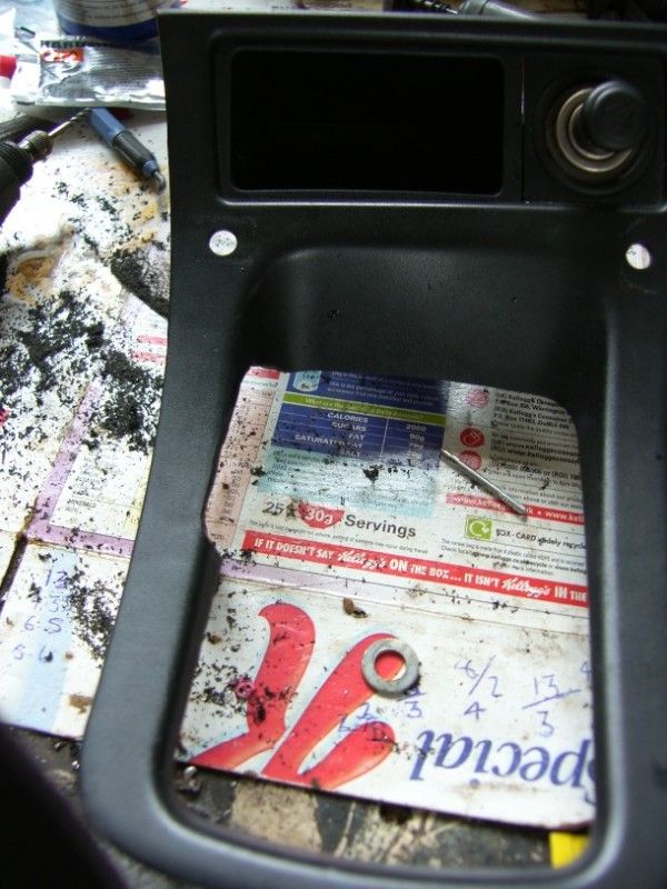
I had an old motorbike under seat heat shield in the garage, it is made from 5 layer nimbus aluminium, perfect for the job. A template was made from the trusty cereal box
This was transferred onto the nimbus -
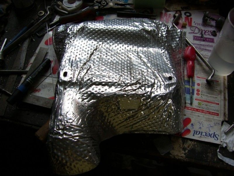
After a bit more dicking around with a hammer / dolly / shears, it was fitting quite well. I folded the edges over to prevent shredding my hands to pieces, and then prepared a bracket to hold the base away from the turbo -
This was pop riveted on to the shield -
And the whole lot fitted back on -
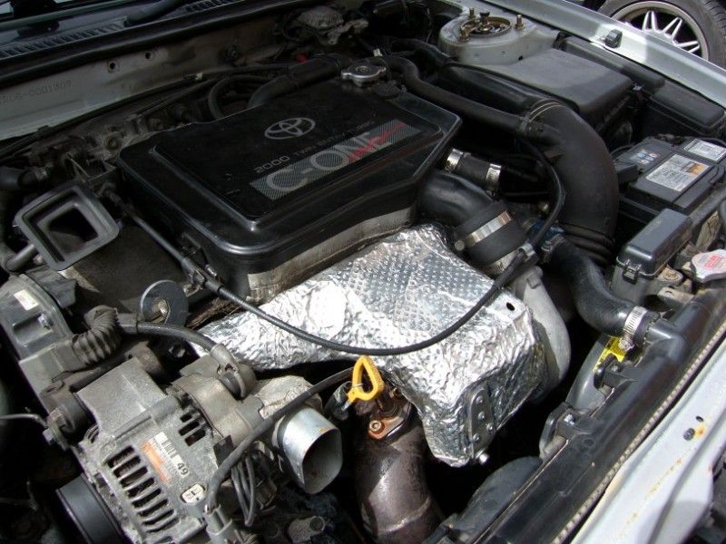
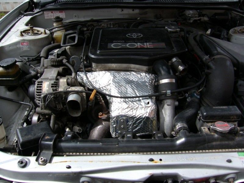
Pretty happy with it, again not my best work but it will do the job required of it, just not very pretty!
At this point my hayfever got so bad I decided to go indoors and sulk, I mean plan for the coming days!
More tomorrow 
J
I finally have some time off!
After starting at Cosworth F1 I have had no holiday at all, and only about half of the weekends, so progress on the car has been slow up to this point :
So with the start of the FOTA enforced shutdown I have just over 2 weeks off, after visiting friends and family over the weekend it is time to get down to the celica
First of all the aligment had not been done since putting coilovers on the car, with the height change the wheels were pointing in all sorts of directions.
Initially the ride height was upped a little (I know, booooo), it was dragging all over the place and touching wheels to inner arches etc. I went up 30mm at the front and 40mm at the back.
Start point -
Up -
After -
Then the alignment could start, this was the first time I had done a string box alignment, but it is how they set up the F1 cars so it must work, and I have watched it done many times.
I started by getting out 4 axle stands and some string (better with fishing wire, but I don't have any of that!), the front and rear widths were matched, as the alignment is done over the whole axle it would appear that the perpendicularity does not matter?
I then proceeded to measure at the front and back of each tyre to get the toe in / out. It had 12mm (yes!) of toe in!!!!!
After a bit of dicking about i got to 1.5mm of toe in, certainly feels a bit more stable now
Next up I decided to try and improve the controls, highest on the list was getting the gear lever a little closer to the steering wheel. As per the previous post I had some carbon tube, this was a perfect starting point as an extension to the lever. The issue with doing this was the increase in lever travel was unacceptable.
The solution? A quick shifter.
Problem? Unavailable.
Time to get cutting!
The ratio for the stock lever is 2.54 for both the front to rear bowden cable and side to side bowden cable. I wanted to reduce this slightly to around 2, even when the lever was extended by 200-250mm.
I cut the kink out of the stock lever to get it closer to the driver, then added a section below the pivot to increase the ratio -
This was then TIG'ed back together -
The issue now was that the bottom of the lever was so long it fouled the body! So the pivot needed moving up, after a bit of searching through the scrap bin I found some 3mm plate and a bit of stainless tube. The tube was cut to 45mm and inserted below the socket for the ball. The upper mounting point then needed securing to the lower lever base, a pair of extension brackets were fabricated to fit, not my best work but they do the job intended.
A pair of spacer tubes were fitted to prevent the base collapsing inwards when bolted up.
After a bit of clearancing with a dremel (the lever was fouling on the base a little in 1st / 2nd), the unit was finish fitted to the car -
The lever height is not fixed yet, it will take a little bit of adjustment, but I am quite happy with the result, much closer to the steering wheel -
Today, I decided that the car was in need of a heat shield for the turbo / manifold, it was missing the stock item when I bought the car and had a piece of chequer plate in its place, mmmm tasteful!
I had an old motorbike under seat heat shield in the garage, it is made from 5 layer nimbus aluminium, perfect for the job. A template was made from the trusty cereal box
This was transferred onto the nimbus -
After a bit more dicking around with a hammer / dolly / shears, it was fitting quite well. I folded the edges over to prevent shredding my hands to pieces, and then prepared a bracket to hold the base away from the turbo -
This was pop riveted on to the shield -
And the whole lot fitted back on -
Pretty happy with it, again not my best work but it will do the job required of it, just not very pretty!
At this point my hayfever got so bad I decided to go indoors and sulk, I mean plan for the coming days!
More tomorrow 
J
August 10th 2012
Well yesterday I had by first go a some proper bodywork spraying, one rear wing, and the sill / lower wing on the other side.... in silver metallic with a lacquer...... outside
It did not go entirely to plan, but the car is now all the same colour and the finish is not catastrophic. I just have to be patient and see how it looks after feathering in and a cut / polish.
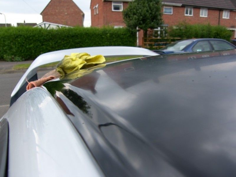
Got up early this morning, wiped the dew off the roof of the celica, masked it up and then proceeded to spray it black! The finish is pretty even, I just need to wait for it to harden over the coming week and then cut it back to a shiny finish
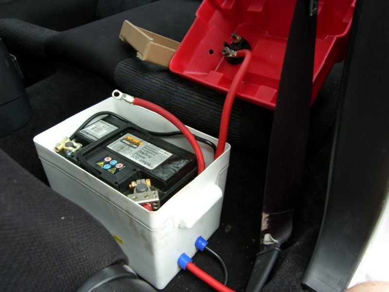
The battery box has arrived already! It fits where intended too, so that will be going in today freeing up lots of space for the straight intake 8)
And on that note, I have ordered the 70mm pipe to run between the box and turbo, it is this stuff -
http://www.ebay.co.uk/itm/70mm-2-3-4-BLUE-Silicone...
Should be ideal for the turbo intake side.
So as it stands, the items left on the list before the retro rides gathering next week are -
Smooth in painted sections (silver)
Cut and polish painted sections (roof and sill/wing)
Paint rear numberplate panel black
Paint bonnet grill black
Fix in battery box (behind passenger seat)
Wire in kill switch and battery
Build air box
Fabricate straight intake
Put extra tabs on heat shield
Modify gear stick gater to fit over quick shifter
Buy and fit blanking plug for dump valve take off
Replace radiator top hose (the reinforcement is failing inside I think)
Find clicking noise on driver side front (sounds brake related?)
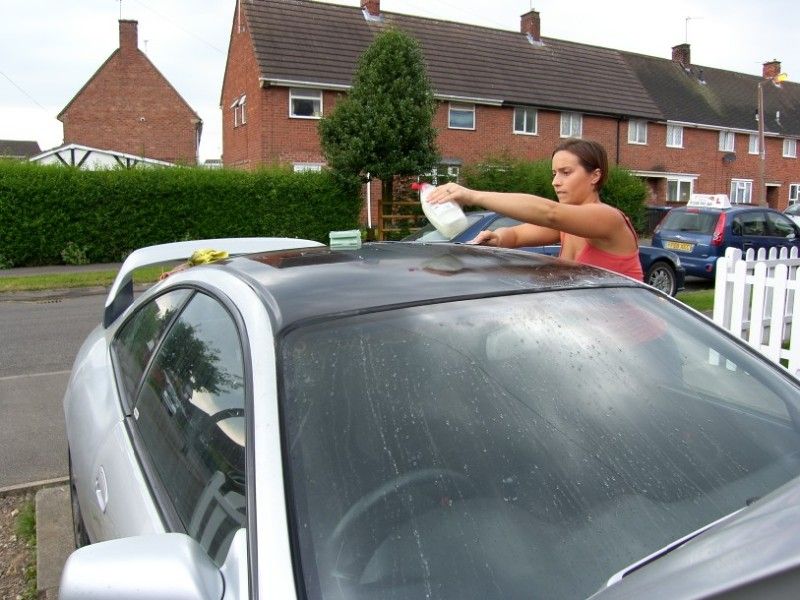
Give the car a damn good wash / clay bar / polish / wax!
I will keep you all up to date over the coming days
Cheers
J
Well yesterday I had by first go a some proper bodywork spraying, one rear wing, and the sill / lower wing on the other side.... in silver metallic with a lacquer...... outside
It did not go entirely to plan, but the car is now all the same colour and the finish is not catastrophic. I just have to be patient and see how it looks after feathering in and a cut / polish.
Got up early this morning, wiped the dew off the roof of the celica, masked it up and then proceeded to spray it black! The finish is pretty even, I just need to wait for it to harden over the coming week and then cut it back to a shiny finish
The battery box has arrived already! It fits where intended too, so that will be going in today freeing up lots of space for the straight intake 8)
And on that note, I have ordered the 70mm pipe to run between the box and turbo, it is this stuff -
http://www.ebay.co.uk/itm/70mm-2-3-4-BLUE-Silicone...
Should be ideal for the turbo intake side.
So as it stands, the items left on the list before the retro rides gathering next week are -
Smooth in painted sections (silver)
Cut and polish painted sections (roof and sill/wing)
Paint rear numberplate panel black
Paint bonnet grill black
Fix in battery box (behind passenger seat)
Wire in kill switch and battery
Build air box
Fabricate straight intake
Put extra tabs on heat shield
Modify gear stick gater to fit over quick shifter
Buy and fit blanking plug for dump valve take off
Replace radiator top hose (the reinforcement is failing inside I think)
Find clicking noise on driver side front (sounds brake related?)
Give the car a damn good wash / clay bar / polish / wax!
I will keep you all up to date over the coming days
Cheers
J
August 13th 2012
Bit more progress
I got a negative terminal from halfrauds so the battery box could be finished up, it is very neat and works perfectly
Next I tried to get the gater and plastic cover round the quick shift gear linkage, not happening
The issue was the left to right linkage touching the surround, a bit of dremel action later and we had clearance -
The result looks pretty factory, just the way I like it
Might need a little height adjustment, but it all works just the way I wanted it to
All of the rest of the time has been spent colour sanding the roof, it took ages and is a little thin in places (it is just halfrauds rattle cans), but it is shiny and looks pretty good I think
Michelle my good wife also helped
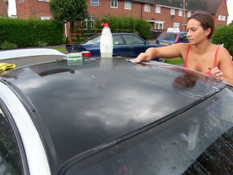
I started to compound it with some G3 -
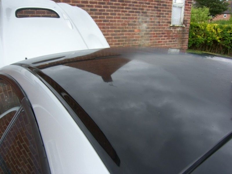
The result looks pretty good I think?
Still needs a wax but I want to do that as late as possible before retro rides gathering
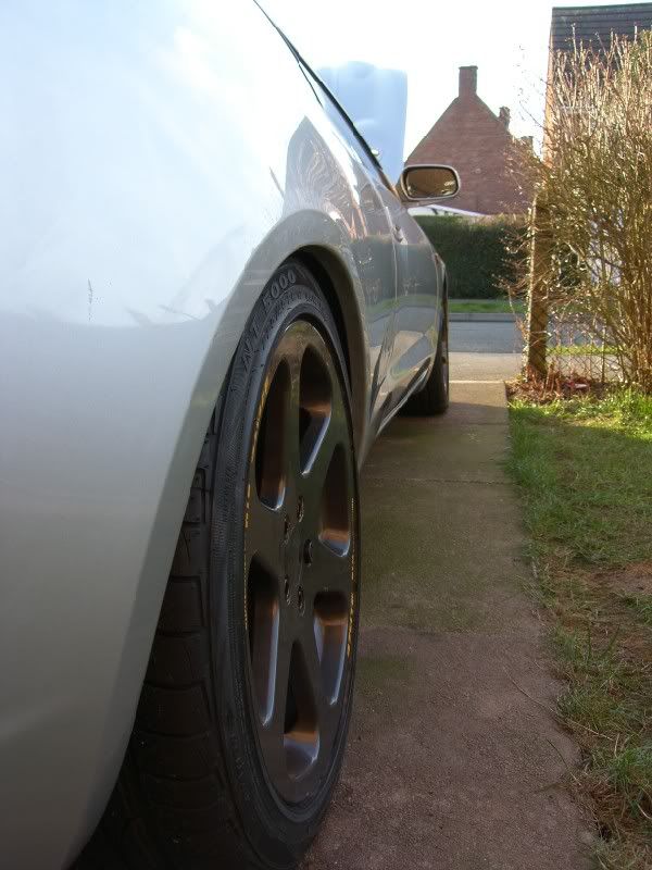
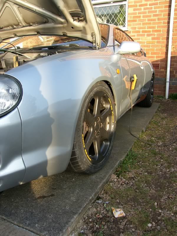
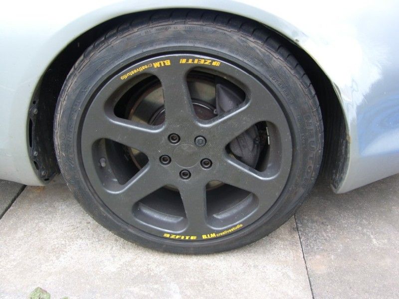
Finally I had a quick tidy up of the wheels, they look a little better, although they are still in need of a refurb. The only issue with that is the stickers, I really don’t want to lose them, even if they are yellow!
Before -
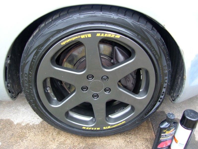
After -
So the list now looks like this -
[strike]Smooth in painted sections (silver)
Cut and polish painted sections (roof and sill/wing)[/strike]
Paint rear numberplate panel black
[strike]Paint bonnet grill black
Fix in battery box (behind passenger seat)
Wire in kill switch and battery[/strike]
Build air box
[strike]Fabricate straight intake[/strike]
Put extra tabs on heat shield
[strike]Modify gear stick gater to fit over quick shifter
Buy and fit blanking plug for dump valve take off[/strike]
Replace radiator top hose (the reinforcement is failing inside I think)
[strike]Find clicking noise on driver side front (sounds brake related?) )[/strike]
Give the car a damn good wash / clay bar / polish / wax!
Change oil
[strike]Clean strut brace bars
Lacquer billet strut brace parts[/strike]
More tomorrow
Bit more progress
I got a negative terminal from halfrauds so the battery box could be finished up, it is very neat and works perfectly
Next I tried to get the gater and plastic cover round the quick shift gear linkage, not happening
The issue was the left to right linkage touching the surround, a bit of dremel action later and we had clearance -
The result looks pretty factory, just the way I like it
Might need a little height adjustment, but it all works just the way I wanted it to
All of the rest of the time has been spent colour sanding the roof, it took ages and is a little thin in places (it is just halfrauds rattle cans), but it is shiny and looks pretty good I think
Michelle my good wife also helped
I started to compound it with some G3 -
The result looks pretty good I think?
Still needs a wax but I want to do that as late as possible before retro rides gathering
Finally I had a quick tidy up of the wheels, they look a little better, although they are still in need of a refurb. The only issue with that is the stickers, I really don’t want to lose them, even if they are yellow!
Before -
After -
So the list now looks like this -
[strike]Smooth in painted sections (silver)
Cut and polish painted sections (roof and sill/wing)[/strike]
Paint rear numberplate panel black
[strike]Paint bonnet grill black
Fix in battery box (behind passenger seat)
Wire in kill switch and battery[/strike]
Build air box
[strike]Fabricate straight intake[/strike]
Put extra tabs on heat shield
[strike]Modify gear stick gater to fit over quick shifter
Buy and fit blanking plug for dump valve take off[/strike]
Replace radiator top hose (the reinforcement is failing inside I think)
[strike]Find clicking noise on driver side front (sounds brake related?) )[/strike]
Give the car a damn good wash / clay bar / polish / wax!
Change oil
[strike]Clean strut brace bars
Lacquer billet strut brace parts[/strike]
More tomorrow
August 26th 2012
Thanks warracer, the wheels seem to be a bit marmite, some love them and some hate them! They are to my taste, that is all that matters 8) I will be getting a refurb at some point probably, not sure, either that or get some new ones, feeling like a change maybe
Well we had a brilliant weekend at retro rides gathering, the car was packed up on friday morning, the dogs sent to the kennels and we set off about 2:30pm taking the Fosse Way, a brilliant road, fast and flowing with plenty of overtaking opportunities
We encountered a bit of friday afternoon traffic about Stow on the Wold, it was the first time I had driven the car in traffic with the paddle clutch, it was not nice! :lol: Judder judder go!
The other side of the village open B roads were the name of the game and what the car has been spec'ed for, the suspension is immense on these bumpy twisty roads, firm and well damped. The twittering from the intake and popping from the exhaust add to the drama, and the new short / long shifter really make the drivers seat a fun place to be
We arrived and the camp site (on a hill and of clay type soil) was water logged from a days rain, all that work cleaning became a bit of a joke, on the bright side the celica behaved as though it was dry, we trundled around stopping to say hello to friends we had not seen in a year and to pick a place to pitch up. Not once did the GT4 slide, wheel spin, or behave anything but the rally weapon it is
By this time the sun had come out and the wet field was starting the slow process of drying out, we picked a good spot and started to put up our new tent. This was the first time it had even been out the bag, we wanted something that was big enough to stand up in and had plenty of space for friends to be in the dry for drinks and general guffaws
What we ended up with was mental, it is actually the biggest tent I have ever seen -

Bonkers!
Now Friday night was a real blur, we had six close friends round to what became known as the “Bedouin Mansion” for Chilli and drinks, this started a bit of a theme, drinks
Michelle my wife had put some ginger beer on to brew whilst I was away working last time round, this was just over 3 weeks before RRG2012, after a few calculations with Jon we came to a figure of 8%ABV. Lets just say my memories of the Friday night are patchy at best!
Saturday I was feeling a little off colour, Michelle drove the faff with me in the passenger seat to Shelsley Walsh, we had a lovely day watching monster hillclimb cars smashing the 30’s sec barrier.
I took a few photos once back at Prescott -
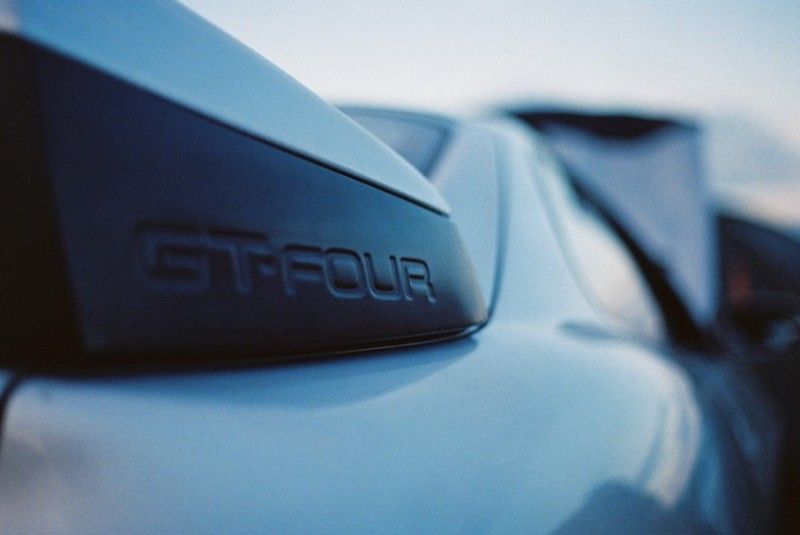
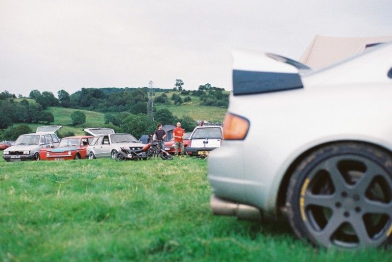
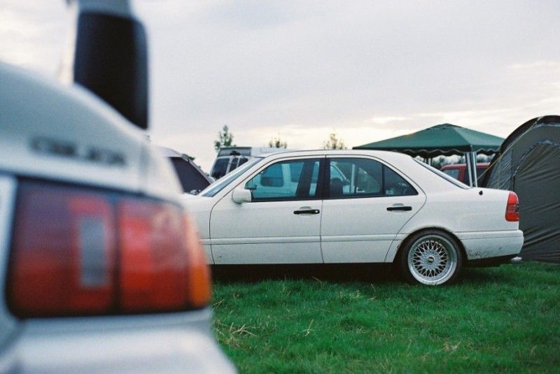
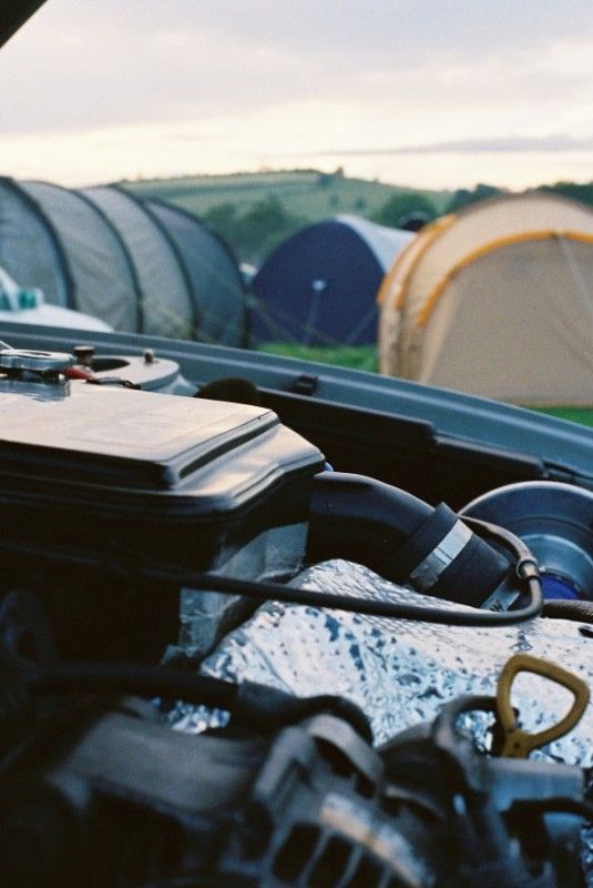
I had built a small spit for our BBQ, so dinner was a 2kg rolled pork loin, cooked for 5hrs over the embers 
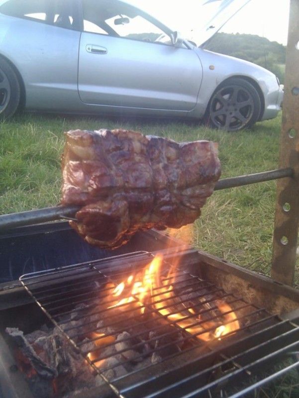
One more picture taken by a friend of the campsite on sat night, beautiful photograph -

Showday on Sunday is something Michelle and I don’t get to see, we work to help keep this wonderful show going, between us we guide cars coming back down from the top of the hillclimb into their respective lanes ready to go back to the start line again. It is non stop all day but well worth it, we meet a lot of people and see lots of cars.
One perk is that we get a guest pass for the hillclimb, the down side is finding time to use it! I got one run up the hill just after the lunch break, proof! -
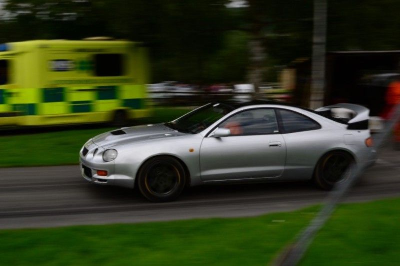
The start was very good I thought, first gear, handbrake on, 5krpm, find the bite point on the clutch and load up the drivetrain, get a little boost, and then simultaneously floor throttle dump clutch and let off handbrake. The result was a very hard start, it pulled straight and true at 1bar with no issues, that clutch is awesome!
I took most of the run very easy, I did not want to bin it on my first go (unlike the R33 skyline driver, off the steep bank last turn on his first run!).
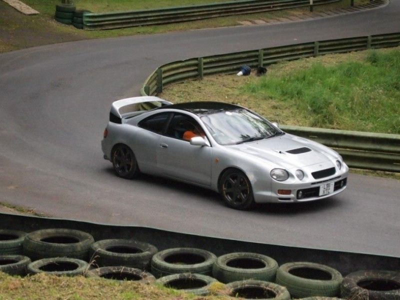
The drive home was uneventful, I did get a chance to show an RS4 which way was up, jolly funny seeing his face as I slowed to let him pass
So where does this leave us?
I think I will be keeping the car longer than I first anticipated, it has got under my skin! The brakes are excellent, the engine has character and punch, driving position is excellent, it grips the same in the wet as it does the dry. Yeah, can’t fault it.
So as it is running well and not broken, I guess it is time to fix it!
The main aims are -
400whp
Less weight over the front wheels
Simplify the turbo system
I am planning to do a split radiator system, a half width triple core Honda radiator, and a half width 100mm core intercooler, similar to Don Boyaks car but on a budget (as all my projects are!).

The theory is that usually our massive radiators are covered up with the charge cooler radiator and only a twin core unit. So a half width triple core unit would be just as capable as the full width standard unit.
The intercooler will be an ebay special used for the core, end tanks cut off and new ones made to suit the location / application.
This will be accompanied with AC removal, new PS / gearbox coolers, and a frame to mount all the new coolers and get rid of more weight from the front end.
I will be fitting one of the IHI RX6d’s that I have available to me, this should provide enough puff to reach my 400whp goal.
A set of 850cc injectors, fuel pump and swirl pot to suit, and then a new piggyback controller to modify fuelling curves to suit.
Watch this space
J
Thanks warracer, the wheels seem to be a bit marmite, some love them and some hate them! They are to my taste, that is all that matters 8) I will be getting a refurb at some point probably, not sure, either that or get some new ones, feeling like a change maybe
Well we had a brilliant weekend at retro rides gathering, the car was packed up on friday morning, the dogs sent to the kennels and we set off about 2:30pm taking the Fosse Way, a brilliant road, fast and flowing with plenty of overtaking opportunities
We encountered a bit of friday afternoon traffic about Stow on the Wold, it was the first time I had driven the car in traffic with the paddle clutch, it was not nice! :lol: Judder judder go!
The other side of the village open B roads were the name of the game and what the car has been spec'ed for, the suspension is immense on these bumpy twisty roads, firm and well damped. The twittering from the intake and popping from the exhaust add to the drama, and the new short / long shifter really make the drivers seat a fun place to be
We arrived and the camp site (on a hill and of clay type soil) was water logged from a days rain, all that work cleaning became a bit of a joke, on the bright side the celica behaved as though it was dry, we trundled around stopping to say hello to friends we had not seen in a year and to pick a place to pitch up. Not once did the GT4 slide, wheel spin, or behave anything but the rally weapon it is
By this time the sun had come out and the wet field was starting the slow process of drying out, we picked a good spot and started to put up our new tent. This was the first time it had even been out the bag, we wanted something that was big enough to stand up in and had plenty of space for friends to be in the dry for drinks and general guffaws
What we ended up with was mental, it is actually the biggest tent I have ever seen -
Bonkers!
Now Friday night was a real blur, we had six close friends round to what became known as the “Bedouin Mansion” for Chilli and drinks, this started a bit of a theme, drinks
Michelle my wife had put some ginger beer on to brew whilst I was away working last time round, this was just over 3 weeks before RRG2012, after a few calculations with Jon we came to a figure of 8%ABV. Lets just say my memories of the Friday night are patchy at best!
Saturday I was feeling a little off colour, Michelle drove the faff with me in the passenger seat to Shelsley Walsh, we had a lovely day watching monster hillclimb cars smashing the 30’s sec barrier.
I took a few photos once back at Prescott -
I had built a small spit for our BBQ, so dinner was a 2kg rolled pork loin, cooked for 5hrs over the embers 
One more picture taken by a friend of the campsite on sat night, beautiful photograph -
Showday on Sunday is something Michelle and I don’t get to see, we work to help keep this wonderful show going, between us we guide cars coming back down from the top of the hillclimb into their respective lanes ready to go back to the start line again. It is non stop all day but well worth it, we meet a lot of people and see lots of cars.
One perk is that we get a guest pass for the hillclimb, the down side is finding time to use it! I got one run up the hill just after the lunch break, proof! -
The start was very good I thought, first gear, handbrake on, 5krpm, find the bite point on the clutch and load up the drivetrain, get a little boost, and then simultaneously floor throttle dump clutch and let off handbrake. The result was a very hard start, it pulled straight and true at 1bar with no issues, that clutch is awesome!
I took most of the run very easy, I did not want to bin it on my first go (unlike the R33 skyline driver, off the steep bank last turn on his first run!).
The drive home was uneventful, I did get a chance to show an RS4 which way was up, jolly funny seeing his face as I slowed to let him pass
So where does this leave us?
I think I will be keeping the car longer than I first anticipated, it has got under my skin! The brakes are excellent, the engine has character and punch, driving position is excellent, it grips the same in the wet as it does the dry. Yeah, can’t fault it.
So as it is running well and not broken, I guess it is time to fix it!
The main aims are -
400whp
Less weight over the front wheels
Simplify the turbo system
I am planning to do a split radiator system, a half width triple core Honda radiator, and a half width 100mm core intercooler, similar to Don Boyaks car but on a budget (as all my projects are!).
The theory is that usually our massive radiators are covered up with the charge cooler radiator and only a twin core unit. So a half width triple core unit would be just as capable as the full width standard unit.
The intercooler will be an ebay special used for the core, end tanks cut off and new ones made to suit the location / application.
This will be accompanied with AC removal, new PS / gearbox coolers, and a frame to mount all the new coolers and get rid of more weight from the front end.
I will be fitting one of the IHI RX6d’s that I have available to me, this should provide enough puff to reach my 400whp goal.
A set of 850cc injectors, fuel pump and swirl pot to suit, and then a new piggyback controller to modify fuelling curves to suit.
Watch this space
J
December 18th 2012
Hi guys, little update on a few things I have been sorting out over the past couple of months and today’s fun
First of all I replaced the clips on the intake system for a pair decent constant tension clips, these are ace as you tighten them up so the spring is under tension, and then it will never come lose or ‘relax’ with age.
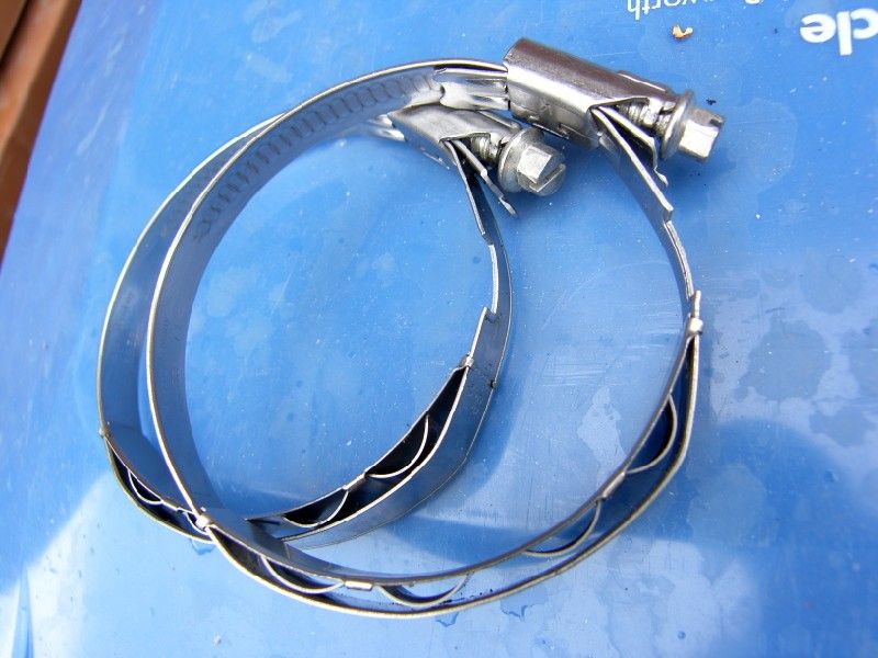
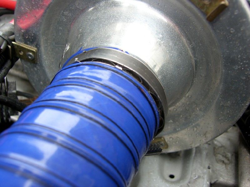
I also spotted this charge cooler on ebay, I can’t decide if it is completely OTT or just right
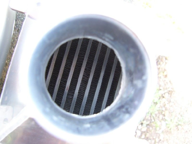
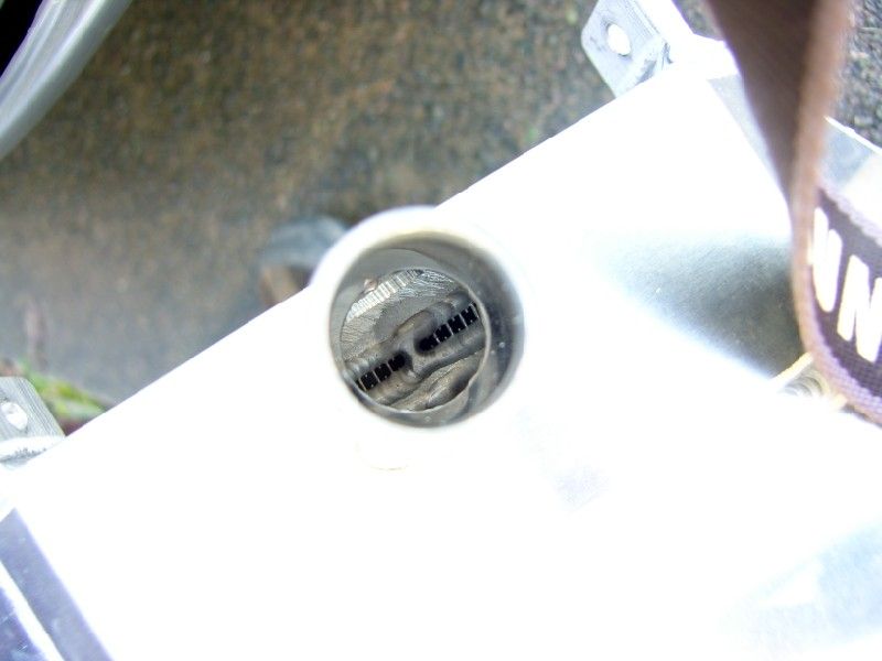

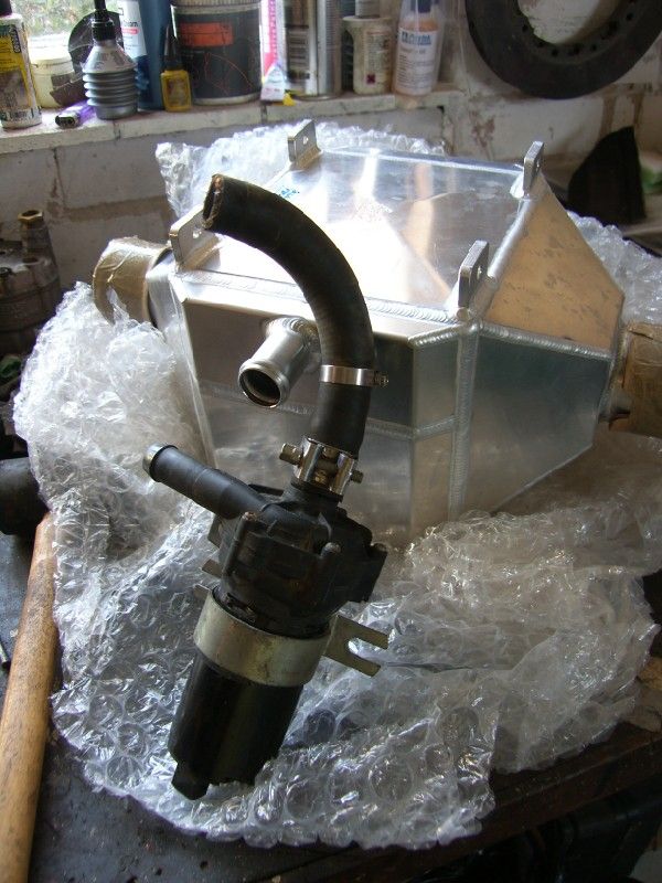
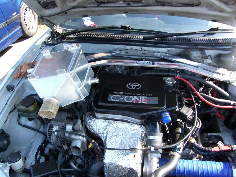
Good for around 550bhp I am really not shooting that high, so I think it might be a bit big really. I might put it back up for sale for someone else who is going for a mental build.
The other thing that I have always wanted is a lamp pod, ideal for our short days and country roads. To begin with I thought the best route was to improve on the stock fog / driving lights, these are located low in the bumper and are quite small. A set of large rally giants or something similar, mounted in a pod would be ideal and quite cheap too.
I started by making two templates, one 200mm and one 225mm, this will allow room for the lamp and mounting at the front, and be a stable base for the lamp on the bumper.
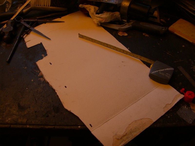
And then transferred that onto some house insulation foam and cut them out roughly with a wood saw.
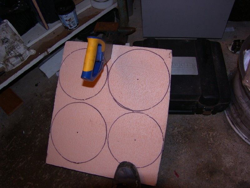
I put them onto a mandrel and roughly shaped them using the saw again, into a kind of cone?
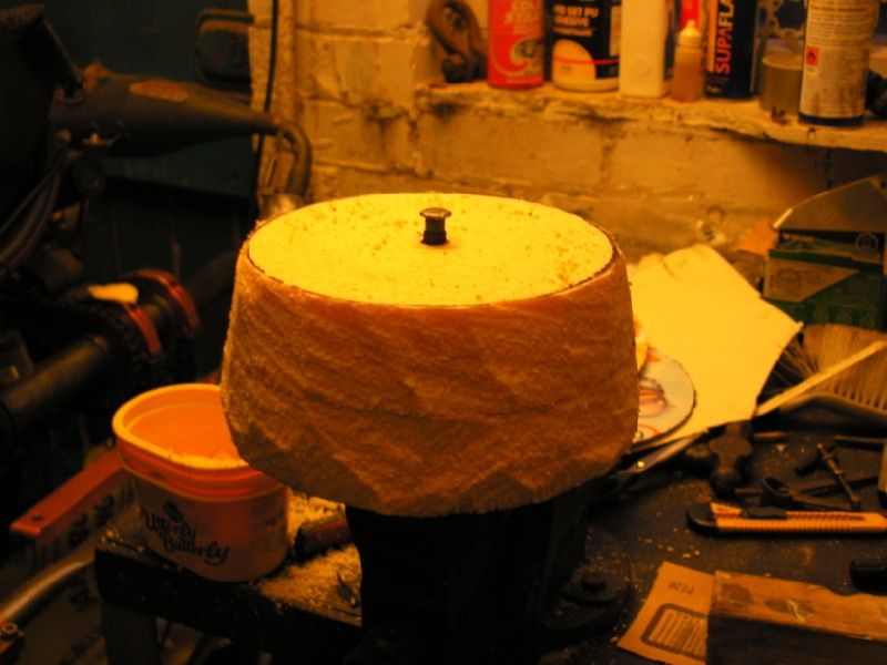
Some 120 grit on a block made a small dent in the shaping but it was a little too slow, so I put them into my cordless drill, got a Stanley knife, and then used the tip like a rotary wood carving lathe! -
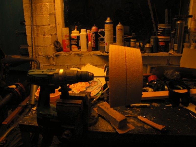
This made quite a lot of mess, but really worked
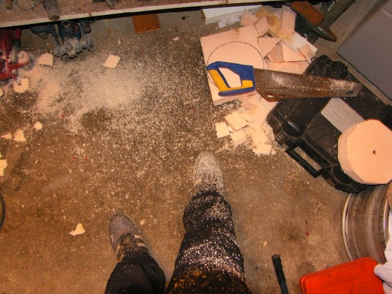
This was then give a light sanding to smooth it out, and the results balanced on the car to see where we were heading. Sorry about the pictures, by this point it was dark
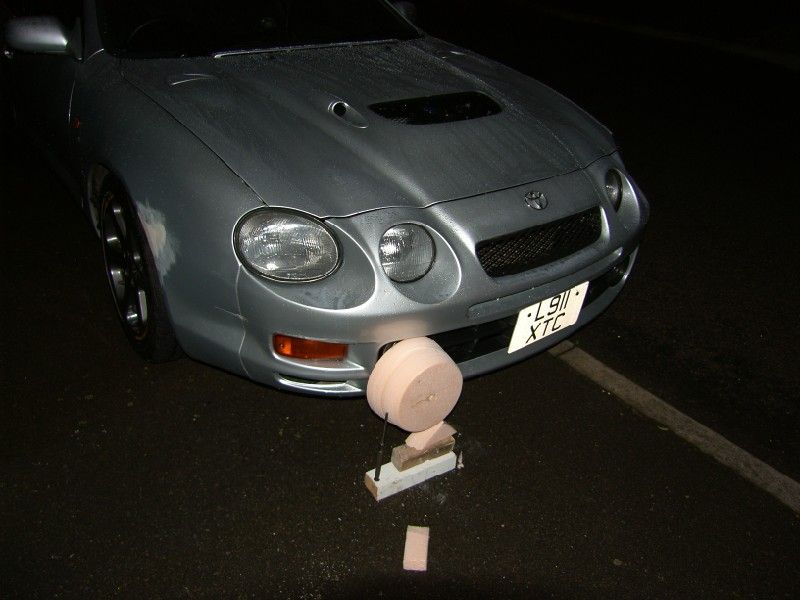
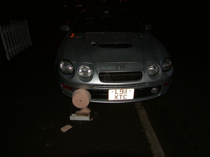
Not too bad, I will cover the front of the car in tape and take a mould of the bumper area it will mount to, then the light pod can be made in two halves and joined. It will have a foam backing in contact with the bumper and then be held in place under tension using the stock fog light mounting bracket
More tomorrow hopefully!
J
Hi guys, little update on a few things I have been sorting out over the past couple of months and today’s fun
First of all I replaced the clips on the intake system for a pair decent constant tension clips, these are ace as you tighten them up so the spring is under tension, and then it will never come lose or ‘relax’ with age.
I also spotted this charge cooler on ebay, I can’t decide if it is completely OTT or just right
Good for around 550bhp
I am really not shooting that high, so I think it might be a bit big really. I might put it back up for sale for someone else who is going for a mental build.The other thing that I have always wanted is a lamp pod, ideal for our short days and country roads. To begin with I thought the best route was to improve on the stock fog / driving lights, these are located low in the bumper and are quite small. A set of large rally giants or something similar, mounted in a pod would be ideal and quite cheap too.
I started by making two templates, one 200mm and one 225mm, this will allow room for the lamp and mounting at the front, and be a stable base for the lamp on the bumper.
And then transferred that onto some house insulation foam and cut them out roughly with a wood saw.
I put them onto a mandrel and roughly shaped them using the saw again, into a kind of cone?
Some 120 grit on a block made a small dent in the shaping but it was a little too slow, so I put them into my cordless drill, got a Stanley knife, and then used the tip like a rotary wood carving lathe! -
This made quite a lot of mess, but really worked
This was then give a light sanding to smooth it out, and the results balanced on the car to see where we were heading. Sorry about the pictures, by this point it was dark
Not too bad, I will cover the front of the car in tape and take a mould of the bumper area it will mount to, then the light pod can be made in two halves and joined. It will have a foam backing in contact with the bumper and then be held in place under tension using the stock fog light mounting bracket
More tomorrow hopefully!
J
January 15th 2013
Time for a small update
Just a bit of tinkering really, my wife, me and the two dogs drove the car all through the christmas period without a hitch (apart from the catastrophic fuel bill!).
The only thing that has been niggling me is the inevitable slight knocking that developed after one too many potholes, I had a really good look at all the joints and there was no play? I used a 3ft crowbar? Looked at bit further and there was a possiblity that the crush tubes might have gone.
I purchased a lovely pair of these JSP items -

After reading the very good installation instructions I realised I would require some way to clean the inside of the bush tube. With no sanding rolls for my dremel, I had to be creative
Take one biro -
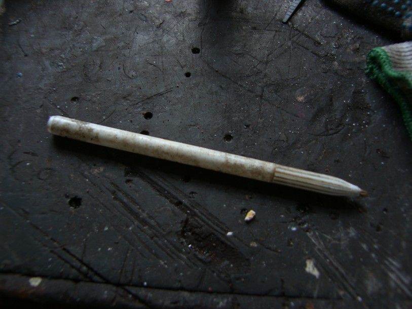
Cut a slit down one side -

Take some emery cloth and roll the end up, then slide it into the slot cut -
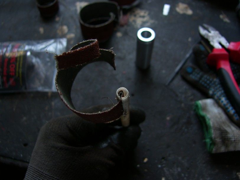
Put the whole lot into your drill ready to clean aforementioned tube
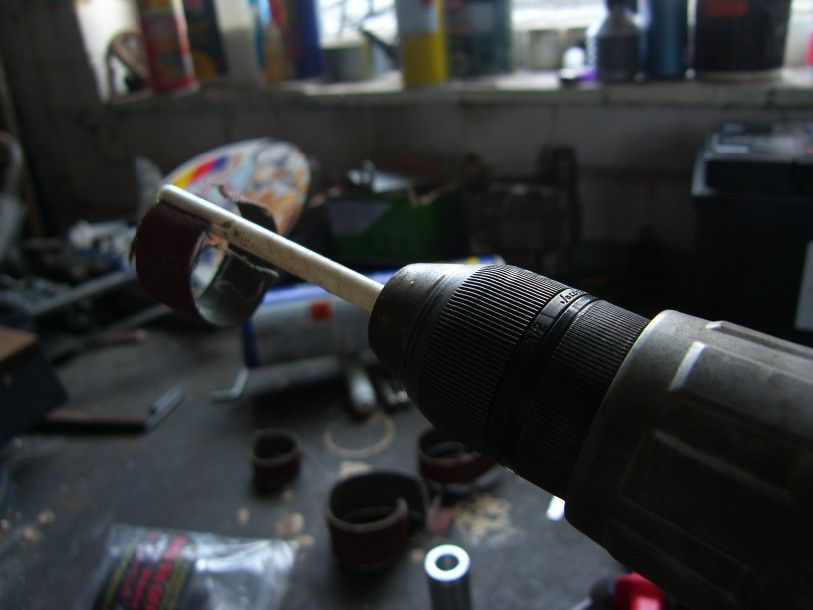
At this point my lovely wife brought out a cup of coffee, so I stopped for 10 mins and warmed up in the sunshine
Back to it, I jacked the car up, 19mm socket on a breaker bar and a short length of scaffold, then pop off the banana bar retaining bolt
I then used the technique suggested in the JSP guide, a screwdriver was 'driven' up the side of the original tube using a small lump hammer :lol: This was repeated in a number of places and the tube collapsed enough for removal.
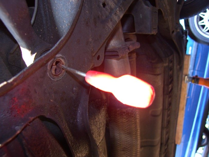
Old and new tubes next to each other -
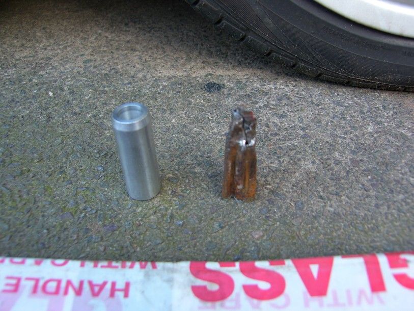
I then broke out the new biro bolthole blaster, and cleaned to my hearts content, it worked a treat
Hard to photograph, but this is the result -
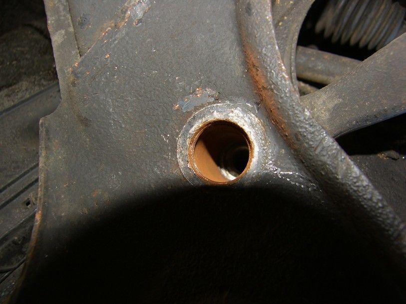
The new tubes were thoroughly greased and then inserted with a gentle tap of a rubber hammer, I did not use copper grease as it reacts with the aluminium causing even worse galvanic corrosion than if it were not used at all!
It was then all torqued up to specs and put back on it's wheels, taken for a drive, and it is still knocking slightly over bumps :confuse:
Might be steering arms?
Oh well, one less thing to think about
Apart from that, the bonnet would not latch down, that was tracked down to the steel loop that is riveted into the aluminium bonnet, losing 3 of the 4 rivets :dunno: These are TOTALLY inaccessable, I decided to get to the easiest one by drilling an access hole, and then bolting the latch down with an M5 stainless bolt and nylock. It will not be going anywhere soon!
Couple of other bits, washer pump stopped momentarily, with a poor connection, soon wiggled back into life
I also checked my catch can after a couple of months of use, nothing but a little overflow from the chargecooler system, no oil, no emulsion, nothing. So I am happy
Back to wales this weekend, ill get more pictures
J
p.s. working conditions have not improved
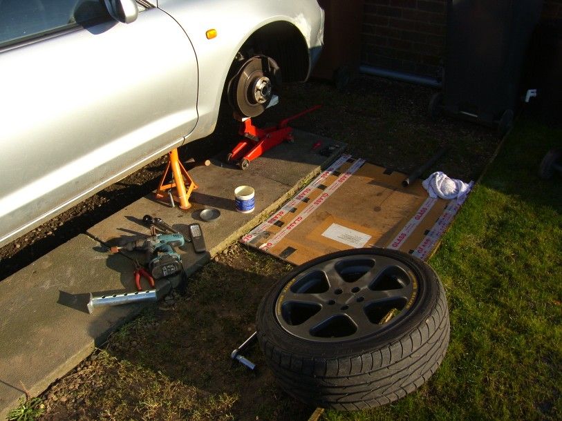
Time for a small update
Just a bit of tinkering really, my wife, me and the two dogs drove the car all through the christmas period without a hitch (apart from the catastrophic fuel bill!).
The only thing that has been niggling me is the inevitable slight knocking that developed after one too many potholes, I had a really good look at all the joints and there was no play? I used a 3ft crowbar? Looked at bit further and there was a possiblity that the crush tubes might have gone.
I purchased a lovely pair of these JSP items -
After reading the very good installation instructions I realised I would require some way to clean the inside of the bush tube. With no sanding rolls for my dremel, I had to be creative
Take one biro -
Cut a slit down one side -
Take some emery cloth and roll the end up, then slide it into the slot cut -
Put the whole lot into your drill ready to clean aforementioned tube
At this point my lovely wife brought out a cup of coffee, so I stopped for 10 mins and warmed up in the sunshine
Back to it, I jacked the car up, 19mm socket on a breaker bar and a short length of scaffold, then pop off the banana bar retaining bolt
I then used the technique suggested in the JSP guide, a screwdriver was 'driven' up the side of the original tube using a small lump hammer :lol: This was repeated in a number of places and the tube collapsed enough for removal.
Old and new tubes next to each other -
I then broke out the new biro bolthole blaster, and cleaned to my hearts content, it worked a treat
Hard to photograph, but this is the result -
The new tubes were thoroughly greased and then inserted with a gentle tap of a rubber hammer, I did not use copper grease as it reacts with the aluminium causing even worse galvanic corrosion than if it were not used at all!
It was then all torqued up to specs and put back on it's wheels, taken for a drive, and it is still knocking slightly over bumps :confuse:
Might be steering arms?
Oh well, one less thing to think about
Apart from that, the bonnet would not latch down, that was tracked down to the steel loop that is riveted into the aluminium bonnet, losing 3 of the 4 rivets :dunno: These are TOTALLY inaccessable, I decided to get to the easiest one by drilling an access hole, and then bolting the latch down with an M5 stainless bolt and nylock. It will not be going anywhere soon!
Couple of other bits, washer pump stopped momentarily, with a poor connection, soon wiggled back into life
I also checked my catch can after a couple of months of use, nothing but a little overflow from the chargecooler system, no oil, no emulsion, nothing. So I am happy
Back to wales this weekend, ill get more pictures
J
p.s. working conditions have not improved
July 7th 2013
Re-wind, start again
Well after much soul searching, the time had come to sell the Celica.
As a family this year, we have sold our house, bought a new one, been made redundant, had major surgery, been gifted our first beautiful child Ruby Madeline, found a new job, quit, found another new job and all the while getting on with normal life stuff!
The Celica dropped down the priority list and ended up being neglected, so after discussions we put it up for a very reasonable price. The result? Very little interest!
It has sat for another month or so, I contemplated splitting it for parts but in consideration of the ball ache in doing so, we concluded it would be a bit pointless.
Whilst moaning about not having a project and feeling very ‘unfulfilled’ my wife and I came to the conclusion that the Celica would be perfect (heard this before?!), and so I finished tidying the new garage and got the Celica parked in it’s new home for the coming months
Today I tucked in to the feast of stripping it down for the projected ideas. I have been contemplating many options, but the main thing will be detail and CLEAN. The shell will be stripped and deficient areas addressed, sill stand tubes added, and thinking of cage to pin the corners together. The front and rear subframes may well have tubular copies made, all the drivetrain will be stripped and coated. The engine will be a side by side rad and intercooler setup, some carbon, some wiggins clamps, and a lot of cleaning and tucking. Electric power steering, new gearbox and PS coolers. IHI RX6d ball bearing F1 turbo (it is already in the cupboard waiting for a suitable project!). Dashboard from another car, something simple, flocked, digidash / android dash, buckets set RIGHT back with extended steering and floor mounted pedals. Finally, new wheels / brakes.
Todays work started with the removal of the bonnet, front wings, and bumper, these were stashed in the roof area of the garage, keeping it tidy as we go along
[img src="http://i27.photobucket.com/albums/c186/twin_charged/Celica/SH105231_zps66e40512.jpg" style="max-width:100%;"]
[img src="http://i27.photobucket.com/albums/c186/twin_charged/Celica/SH105230_zpsf409e522.jpg" style="max-width:100%;"]
One interesting thing for non celica people, are some of the homologation parts fitted to this car, including the charge cooler radiator spray, this is teed off of the windscreen washer tank and sprays the alcohol / water mix over the cooler matrix.
[img src="http://i27.photobucket.com/albums/c186/twin_charged/Celica/P7071230_zpse29b97a1.jpg" style="max-width:100%;"]
These are the jets –
[img src="http://i27.photobucket.com/albums/c186/twin_charged/Celica/P7071231_zpsac916690.jpg" style="max-width:100%;"]
I have stripped off all of the cooling system, that is coolers for -
Engine water
Power steering fluid
Gearbox fluid
Charge cooler water
Air con gas
Remember this is a stock factory car, the engine oil is cooled using a water /oil cooler, so EVERYTHING is catered for!
More parts came off -
[img src="http://i27.photobucket.com/albums/c186/twin_charged/Celica/SH105232_zps7a7eafa6.jpg" style="max-width:100%;"]
The car has had some kind of impact at the front, the lower bar is pretty well deformed. This is no issue though as I will be cutting it out to accommodate the new cooling pack, tubular reinforcement will be put in its place.
[img src="http://i27.photobucket.com/albums/c186/twin_charged/Celica/P7071236_zps1f3caa02.jpg" style="max-width:100%;"]
The flow coming out of the turbo was pretty well defined in the oil vapour deposits! –
[img src="http://i27.photobucket.com/albums/c186/twin_charged/Celica/P7071233_zps31b2c7f2.jpg" style="max-width:100%;"]
This is where we ended up, turbo, downpipe, all cooling pack, lights etc, air con system, and a few more ancillaries all off
[img src="http://i27.photobucket.com/albums/c186/twin_charged/Celica/P7071235_zps628053c1.jpg" style="max-width:100%;"]
I also had a bash at a bit of stop motion, not too much going on but I will keep this up so we have some fun footage by the end of the project
[video src="http://s27.photobucket.com/user/twin_charged/media/Celica/Celica01_zps27aefb4e.mp4.html"][/video]
So, we are moving forwards with the project, I have a lot of tools and materials to purchase over the coming months, that combined with time and a bit of out of the box thinking should leave us with some pretty cool and unusual modifications.
More soon
J
July 11th 2013
Time for a bit of bench tuning 
The Celica uses a jolly complicated cooling pack, this consists of –
Engine water radiator
Power steering fluid
Gearbox fluid
Charge cooler water
Air con gas
The water radiator, air con radiator and charge cooler rad are all stacked one in front of the other too, so the air has to absorb the heat from each successive rad, less than ideal.
The idea is to use a narrow radiator and a narrow air to air intercooler side by side in the nose, this should allow ample cooling capacity with increased efficiency and considerably less weight. The ideal size and shape comes from a Honda Civic -

If you look on this thread, it shows plenty of evo’s running a similar setup but a full width intercooler, they seem to run without issue.
http://forums.evolutionm.net/evo-engine-turbo-driv...
Capacity wise the stock radiator has a volume of 5852cm2 (64x36x2.5), this is 2.926 times the engine capacity, actually quite oversized for the application. It is also a single row system, resulting in a low internal surface area.
The Honda radiator has a capacity of 6860cm2 (35x35x5.6), this is 3.43 times the engine capacity, this should make up for the fact that the air is having to do a little more work on the thicker core. The radiator is also a triple row design, maximising the internal surface area.
So the rad when combined with a good shroud and modern fan should make for an effective cooling system.
Next up I am looking at the exhaust size, the current thinking of the majority is that a 3” post turbo system is needed to make power. I think that this is poppy cock, and plenty of power can be made with a GOOD 2.5” system, possibly smaller.
Now I don’t want to go really small just to prove a point, but a 2.5” system will be much easier to package and still able to flow plenty.
I went through the calculations and came up with a post intercooler flow of 12.48m3/min, considering the increase in volume for a temperature rise of 800 degrees C the post turbo flow was 45.71m3/min.
Next up I calculated the SOS in a gas at 800 degrees C, this was 816m/s.
At this point I got bored and started to use web based calculators, after much digging, calculations in excel and online, I got the following figures –
Post turbo kinematic viscosity 138.6 m2/s x10-6
Post turbo dynamic viscosity 4.44 kg/m s x10-5
SOS@800C
816.1 m/s
density : 800C 0.4737 kg/m3
Reynolds number 1.16 r
Gas compressibility factor 1.0004
Pipe flow 168.8869
Gas constant 8.3145
Using these I got the maximum possible velocity in a 3” pipe of 655m/s, this is limited lower than the SOS due to the internal friction (it is possible to go higher, but the gas will abrade the pipe material).
Finally the for the temperature, gas, density, and pipe size, the peak flow speed will be around 244m/s, less than half the maximum possible. Even at 2bar boost the flow is only 326m/s.
Therefore I am going to use a 2.5” exhaust system, it will allow plenty of scope for further tuning and be much easier to package.
Just out of interest, look here for Subaru WRC stuff
http://www.subaruwrcspares.com/11.html
2.5” for gravel and 3” for tarmac, and that is MEGA boost at low RPM and huge torque
Other than that, some parts have started arriving, we have some 8mm cobalt spot weld drills to remove some of the bent metal at the front of the car. The new jack also arrived, this I am very impressed with, it is a partial aluminium jack with the lifting parallelogram in steel, 25kg so not hard to move around either. Couple of pics to brighten things up 
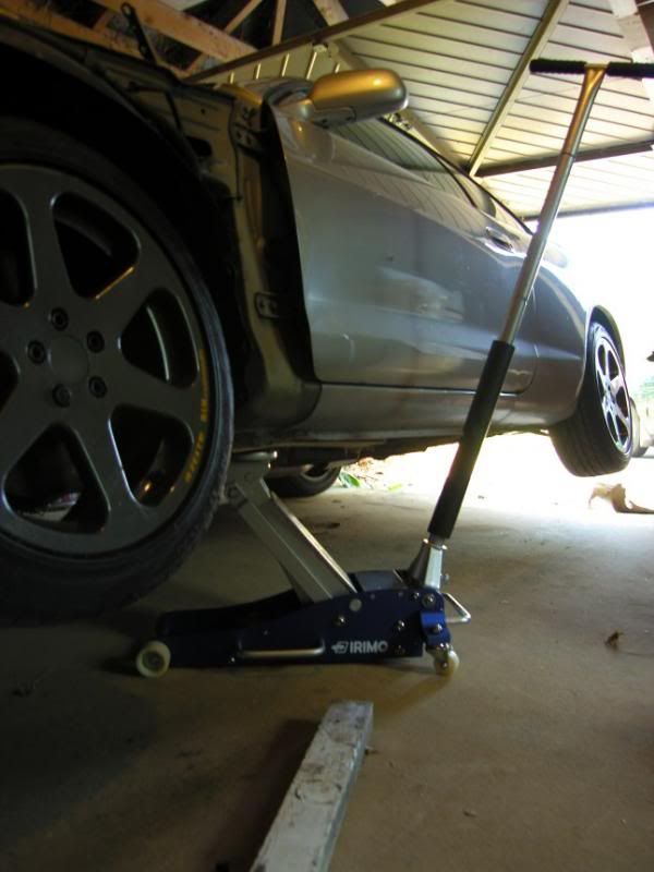
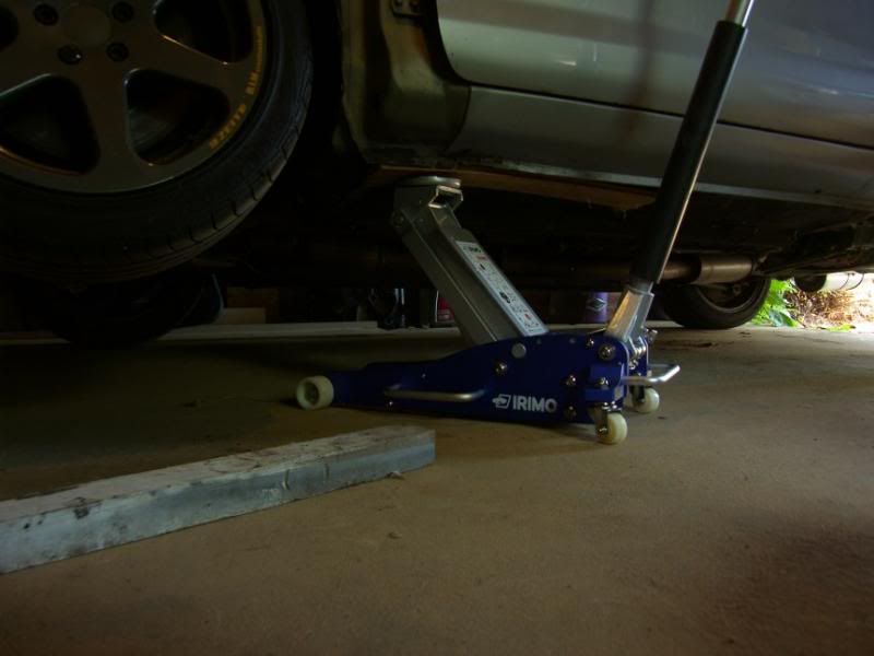
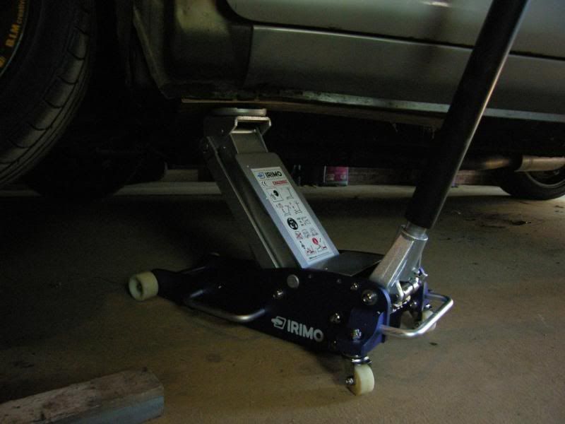
More soon
J
Time for a bit of bench tuning 
The Celica uses a jolly complicated cooling pack, this consists of –
Engine water radiator
Power steering fluid
Gearbox fluid
Charge cooler water
Air con gas
The water radiator, air con radiator and charge cooler rad are all stacked one in front of the other too, so the air has to absorb the heat from each successive rad, less than ideal.
The idea is to use a narrow radiator and a narrow air to air intercooler side by side in the nose, this should allow ample cooling capacity with increased efficiency and considerably less weight. The ideal size and shape comes from a Honda Civic -
If you look on this thread, it shows plenty of evo’s running a similar setup but a full width intercooler, they seem to run without issue.
http://forums.evolutionm.net/evo-engine-turbo-driv...
Capacity wise the stock radiator has a volume of 5852cm2 (64x36x2.5), this is 2.926 times the engine capacity, actually quite oversized for the application. It is also a single row system, resulting in a low internal surface area.
The Honda radiator has a capacity of 6860cm2 (35x35x5.6), this is 3.43 times the engine capacity, this should make up for the fact that the air is having to do a little more work on the thicker core. The radiator is also a triple row design, maximising the internal surface area.
So the rad when combined with a good shroud and modern fan should make for an effective cooling system.
Next up I am looking at the exhaust size, the current thinking of the majority is that a 3” post turbo system is needed to make power. I think that this is poppy cock, and plenty of power can be made with a GOOD 2.5” system, possibly smaller.
Now I don’t want to go really small just to prove a point, but a 2.5” system will be much easier to package and still able to flow plenty.
I went through the calculations and came up with a post intercooler flow of 12.48m3/min, considering the increase in volume for a temperature rise of 800 degrees C the post turbo flow was 45.71m3/min.
Next up I calculated the SOS in a gas at 800 degrees C, this was 816m/s.
At this point I got bored and started to use web based calculators, after much digging, calculations in excel and online, I got the following figures –
Post turbo kinematic viscosity 138.6 m2/s x10-6
Post turbo dynamic viscosity 4.44 kg/m s x10-5
SOS@800C
816.1 m/s
density : 800C 0.4737 kg/m3
Reynolds number 1.16 r
Gas compressibility factor 1.0004
Pipe flow 168.8869
Gas constant 8.3145
Using these I got the maximum possible velocity in a 3” pipe of 655m/s, this is limited lower than the SOS due to the internal friction (it is possible to go higher, but the gas will abrade the pipe material).
Finally the for the temperature, gas, density, and pipe size, the peak flow speed will be around 244m/s, less than half the maximum possible. Even at 2bar boost the flow is only 326m/s.
Therefore I am going to use a 2.5” exhaust system, it will allow plenty of scope for further tuning and be much easier to package.
Just out of interest, look here for Subaru WRC stuff
http://www.subaruwrcspares.com/11.html
2.5” for gravel and 3” for tarmac, and that is MEGA boost at low RPM and huge torque
Other than that, some parts have started arriving, we have some 8mm cobalt spot weld drills to remove some of the bent metal at the front of the car. The new jack also arrived, this I am very impressed with, it is a partial aluminium jack with the lifting parallelogram in steel, 25kg so not hard to move around either. Couple of pics to brighten things up 
More soon
J
July 20th 2013
Hi chaps,
A little more progress, I have finally managed to find a reasonable free 2D CAD program to enable me to draw up some flanges and get them water cut. It turns out that just round the corner in our tiny village, there is a cutting company capable of LASER, water, plasma and gas cutting. Ideal!
I should have those drawn up by tomorrow and have them out for quote on Monday.
I have been struggling to find an intercooler or even just a core that will fit in the nose of the celica, once a radiator is wedged in there too it is just tight. It is ok for the Subaru and Evo boys, they have a big saloon car with a tall nose, the wedgy celica is very low resulting in not much space. I refuse to have radiators one in front of the other due to the reduction in delta T across the core.
Previously I had spoken about a larger charge cooler I got for a steal, the core of this supposedly will support 500hp.
If the stock CC core is 20x30x7cm this is an capacity of 4200cc
The new CC core is 16x18x20cm, a capacity of 5760cc
As a basic comparison the celica CC can make 1hp/12cc (a conservative 350bhp)
At the same capacity the new CC should be capable of 480hp, in fact the core is a more efficient bar and plate type with a higher number of fins per unit area, so could make more.
Another good comparison is the amount of open face to the air flow, the celica has 210cm2, the new cooler has 320cm2, again considerably larger. I am confident this is an ideal upgrade for the projected turbocharger and engine setup.
So it was offered up and an ideal site found, this was previously dead space taken up by pipes, so will be put to good use.
[img src="http://i27.photobucket.com/albums/c186/twin_charged/Celica/SH105366_zps86246e97.jpg" style="max-width:100%;"]
[img src="http://i27.photobucket.com/albums/c186/twin_charged/Celica/SH105367_zps555692d6.jpg" style="max-width:100%;"]
Fits like a dream!
Next up I started looking at radiators to cool the CC and engine, the hole to fit them in is 670mm x 420mm, this is between the inner lights to the bottom of the lower cross member. My original plan to use a Honda radiator was scuppered by the fact they are 470mm deep, way lower than the cross member and liable to be clipped when pressing on
More investigation revealed that a Renault 5 turbo radiator is around 400 x 420mm, ideal for the space and available in a 70mm thick core rated to 500hp, ideal
This leaves 270mm width for the charge cooler pre-rad, more digging shows that the mini uses a radiator that is 270x260mm, fits the hole and again, available in 70mm thickness.
Now just for comparisons sake, the celica radiator core is 35x65x2.4cm this is a volume of 5460cc. The Renault rad core is 31x39x7, a volume of 8463cc, adequate!
The CC pre rad on the celica is 22.5x65x3.5 = 5119cc the mini rad 26x27x7 = 4914, comparable. I hope with a fan, some good ducting and a decent header tank set up it will perform well enough.
With all this scoped out, I eyed up the wastegate and my options. There are two available in budget, buy a Chinese knock off 50mm item, or use one that I have collected in the past. Now these arrived with the turbochargers I got many years ago, they are a 45mm valve with a well insulated diaphragm and chamber, and the body is die cast steel.
[img src="http://i27.photobucket.com/albums/c186/twin_charged/Celica/SH105371_zps9402c296.jpg" style="max-width:100%;"]
[img src="http://i27.photobucket.com/albums/c186/twin_charged/Celica/SH105370_zpsf7381da8.jpg" style="max-width:100%;"]
As you can see, I have got a few of them, so plenty of spares!
[img src="http://i27.photobucket.com/albums/c186/twin_charged/Celica/SH105372_zpsf510954d.jpg" style="max-width:100%;"]
The only issue is the inlet side of wastegate, it is an unknown V band flange. I will do some measuring and hopefully find a standard size item that will fit.
So, in need of some more motivation, I decided to mock up the turbo position, charge cooler and wastegate. These are not fixed but give me a good idea as to how the package will work.
[img src="http://i27.photobucket.com/albums/c186/twin_charged/Celica/SH105377_zpsdc8abc71.jpg" style="max-width:100%;"]
[img src="http://i27.photobucket.com/albums/c186/twin_charged/Celica/SH105383_zpsc5db7738.jpg" style="max-width:100%;"]
[img src="http://i27.photobucket.com/albums/c186/twin_charged/Celica/SH105385_zpsb2453b57.jpg" style="max-width:100%;"]
As you can see, the charge cooler end tanks will need to be chopped off and a new set fabricated, the turbo will blow directly into the core, through to the right hand side and out of a new end tank that will direct it towards the intake.
[img src="http://i27.photobucket.com/albums/c186/twin_charged/Celica/SH105381_zps451d0f97.jpg" style="max-width:100%;"]
[img src="http://i27.photobucket.com/albums/c186/twin_charged/Celica/SH105373_zpsc650e994.jpg" style="max-width:100%;"]
[img src="http://i27.photobucket.com/albums/c186/twin_charged/Celica/SH105386_zps211ba7cc.jpg" style="max-width:100%;"]
[img src="http://i27.photobucket.com/albums/c186/twin_charged/Celica/SH105380_zps0866d9e7.jpg" style="max-width:100%;"]
The wastegate will move lower and a little closer to the turbo, but in that space a down pipe will also have to reside, so the space will be a little more critical.
So next things to get sorted are mounting the charge cooler, building an adaptor for the turbocharger to std exhaust manifold and a turbocharger support, and get some parts to start building a down pipe.
I think I might use one of the excellent gt4oc ST205 WRC replica air boxes, a little more expensive than I would normally go for, but such a neat solution and I will be happy in the knowledge that it is a proven design.
More tomorrow.
J
July 30th 2013
Little update
A few parts have been arriving including two radiators and a throttle body
I have been scribbling ideas for pipe routing and tank / radiator locations, this is what I am thinking (please excuse the poor biro work!)
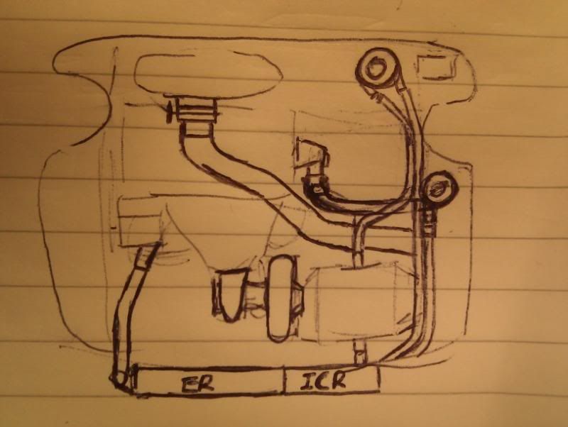
A 2L header tank for the charge cooler will be bulkhead mounted with a bottom feed going to a Bosch electric water pump, into the charge cooler then rad and back to the tank.
The radiator will have a swirl pot header tank located in front of the passenger turret allowing air to escape and hopefully improve the performance of the system.
I was greeted by this parcel when I got home today, and duly started ripping it open like a six year old on christmas day
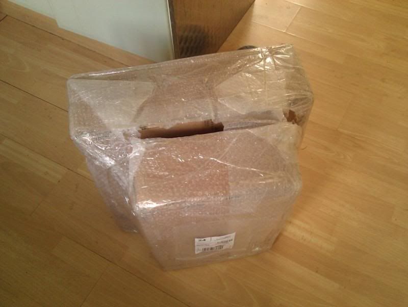
They were rushed out to the garage and tried in the hole, scary bit as I was not certain they would fit! This is how they fit best at the moment, without any cutting -
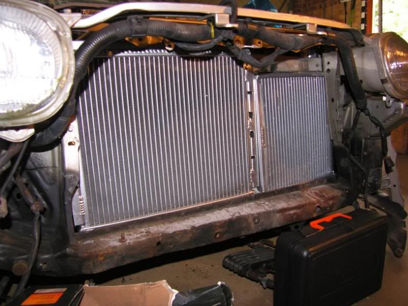
The issue is the amount of space behind the rads, it is all getting a bit cosy back there! I think there is around 5cm between the compressor outlet and the rads.
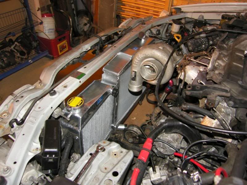
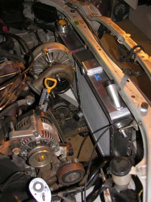
Adequate but not ideal.
I have got to remove and replace the lower bar anyway on this car, due to damage and corrosion. The option is to replace it with a smaller stronger fabrication giving me room to fit them in front of the bar, under the top cross member. This will allow room for the extra height, for the rear mounted inlet / outlets and for rad fans an cowlings.
The throttle body arrived too, this will fit onto the stock intake manifold mostly to aesthetic reasons! It will be less restrictive than the stock item, and also considerably more simple, smoothing the lines a little
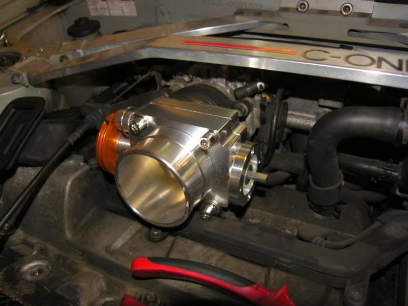
The only other thing to arrive was a set of tungsten carbide burrs for my rotary tool, £7, god bless China!
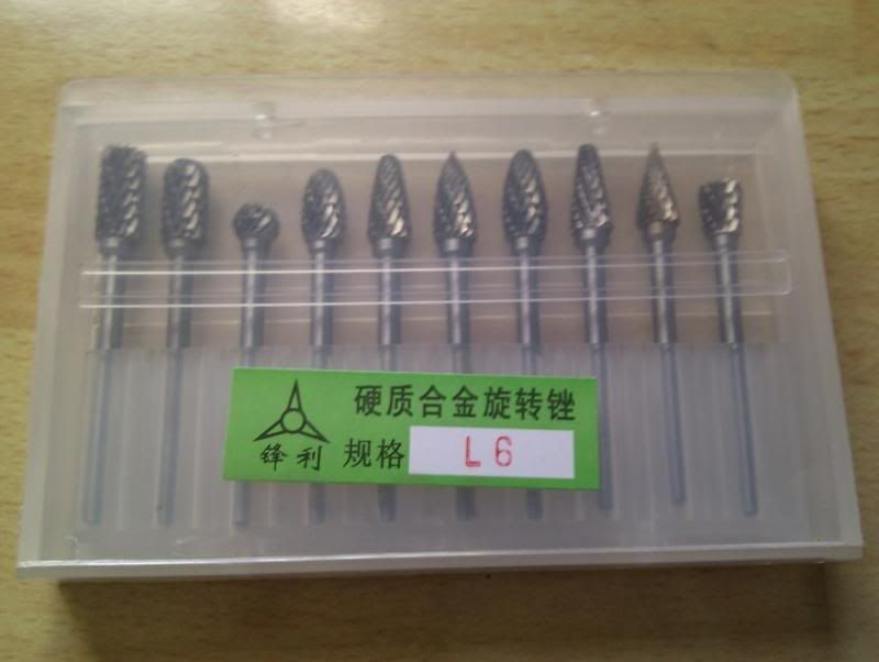
That is all for now, slowly slowly catchy monkey
J
Little update
A few parts have been arriving including two radiators and a throttle body
I have been scribbling ideas for pipe routing and tank / radiator locations, this is what I am thinking (please excuse the poor biro work!)
A 2L header tank for the charge cooler will be bulkhead mounted with a bottom feed going to a Bosch electric water pump, into the charge cooler then rad and back to the tank.
The radiator will have a swirl pot header tank located in front of the passenger turret allowing air to escape and hopefully improve the performance of the system.
I was greeted by this parcel when I got home today, and duly started ripping it open like a six year old on christmas day
They were rushed out to the garage and tried in the hole, scary bit as I was not certain they would fit! This is how they fit best at the moment, without any cutting -
The issue is the amount of space behind the rads, it is all getting a bit cosy back there! I think there is around 5cm between the compressor outlet and the rads.
Adequate but not ideal.
I have got to remove and replace the lower bar anyway on this car, due to damage and corrosion. The option is to replace it with a smaller stronger fabrication giving me room to fit them in front of the bar, under the top cross member. This will allow room for the extra height, for the rear mounted inlet / outlets and for rad fans an cowlings.
The throttle body arrived too, this will fit onto the stock intake manifold mostly to aesthetic reasons! It will be less restrictive than the stock item, and also considerably more simple, smoothing the lines a little
The only other thing to arrive was a set of tungsten carbide burrs for my rotary tool, £7, god bless China!
That is all for now, slowly slowly catchy monkey
J
July 31st 2013
Small update after thinking about a post from one of the GT4OC members about chassis balance and putting everything way out front
I dismantled more things in the engine bay, and if I do a bit of loom work to move it out of the way, then the charge cooler *just* fits

Those tabs peeking up there can be cut off and the charge cooler mounted from below.
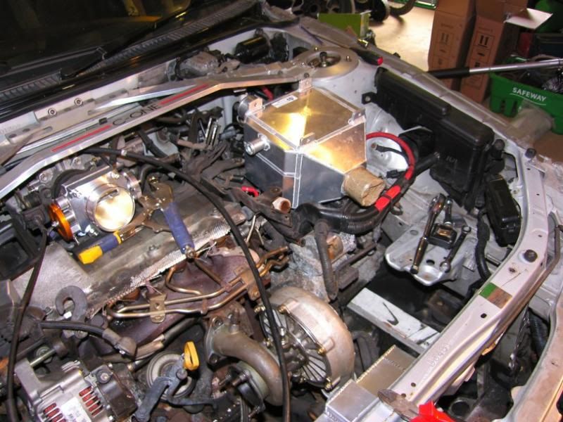
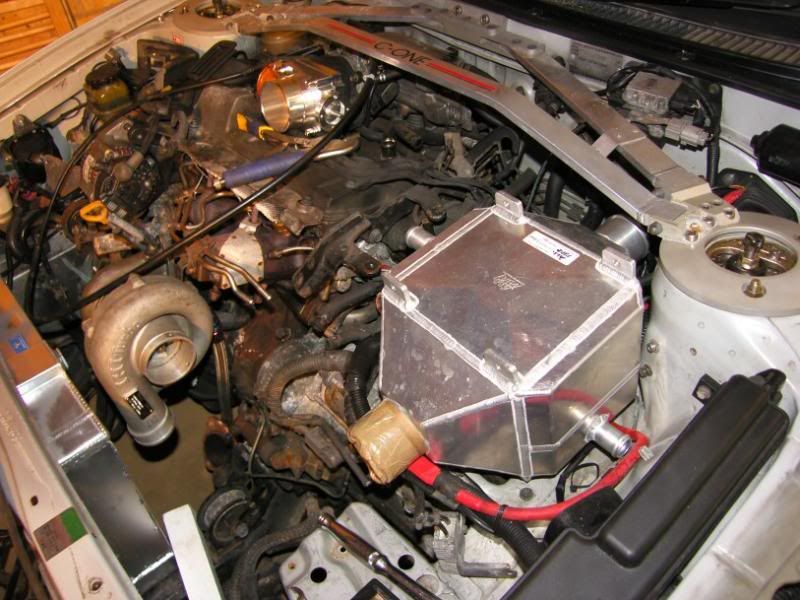
The header tanks and pipe routing will have to be re-thunk but that is okies, I will get sketching later
The charge piping will be a little more simple due to the direction of the 'cooler, 135 deg on the CC and 135 deg on the TB, job done!
Here is a little one for the non GT4 guys, it is the OEM water injection nozzle, all plumbed and wired in. There is so much stuff on this car for homologation purposes it is crazy. I really wish that new competition cars required homologation, then we would start getting proper bonkers road cars again
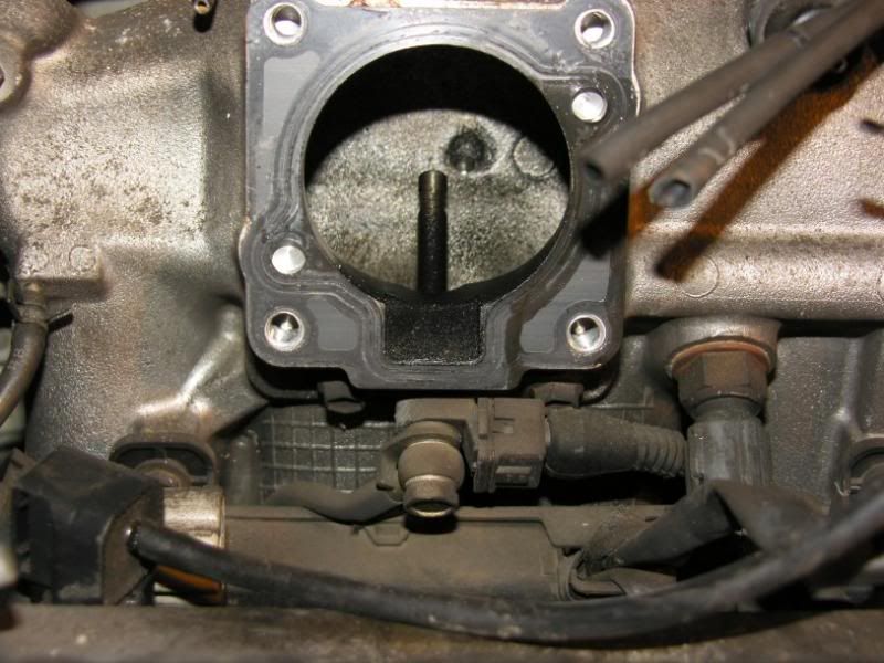
I have been doing some fun maths on the radiator system, a little look at evans coolant put me right off, with a low specific heat capacity and low thermal conductivity, it seems a little pointless. It is designed to prevent micro boiling and cavitation to improve heat transfer in problem areas / cooling systems.
One thing that really stuck in my mind from last year was the cooling systems, F1 engines use water with 2% corrosion inhibitor, that is it. They also run up to and over 150 degrees water temperature. Yep. High isn't it!
As long as the system pressure remains above the vapour pressure at a given temperature, the water WON'T boil
They way this is achieved is using a sealed cooling system that is pre-pressurised at a given temperature, with a specific volume of air left in (measured to 1cc). The system volume is known and so is the air volume, so the expansion of the water can be calculated and the air will act as a spring maintaining pressure.
I have done the maths on the system now and know what air volume I need, what pressure and how it behaves under most conditions. Only one way to find out if it works!
Right, dinner time!
Big hugs, J
Small update after thinking about a post from one of the GT4OC members about chassis balance and putting everything way out front
I dismantled more things in the engine bay, and if I do a bit of loom work to move it out of the way, then the charge cooler *just* fits
Those tabs peeking up there can be cut off and the charge cooler mounted from below.
The header tanks and pipe routing will have to be re-thunk but that is okies, I will get sketching later
The charge piping will be a little more simple due to the direction of the 'cooler, 135 deg on the CC and 135 deg on the TB, job done!
Here is a little one for the non GT4 guys, it is the OEM water injection nozzle, all plumbed and wired in. There is so much stuff on this car for homologation purposes it is crazy. I really wish that new competition cars required homologation, then we would start getting proper bonkers road cars again
I have been doing some fun maths on the radiator system, a little look at evans coolant put me right off, with a low specific heat capacity and low thermal conductivity, it seems a little pointless. It is designed to prevent micro boiling and cavitation to improve heat transfer in problem areas / cooling systems.
One thing that really stuck in my mind from last year was the cooling systems, F1 engines use water with 2% corrosion inhibitor, that is it. They also run up to and over 150 degrees water temperature. Yep. High isn't it!
As long as the system pressure remains above the vapour pressure at a given temperature, the water WON'T boil
They way this is achieved is using a sealed cooling system that is pre-pressurised at a given temperature, with a specific volume of air left in (measured to 1cc). The system volume is known and so is the air volume, so the expansion of the water can be calculated and the air will act as a spring maintaining pressure.
I have done the maths on the system now and know what air volume I need, what pressure and how it behaves under most conditions. Only one way to find out if it works!
Right, dinner time!
Big hugs, J
August 11th 2013
Bit of an update today, I got brave!
First off though, I finally managed to set up my garage PC
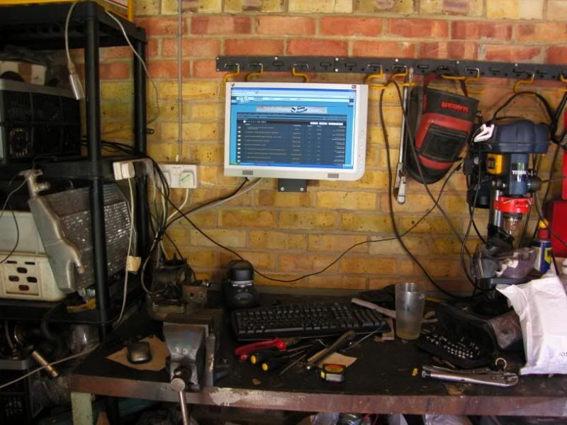
So I now spend a lot less time running in and out, and it is safer than having the laptop on my workbench
Now for the brave bit, as you know I have been a bit tight on space for the cooling pack and I also want to replace the front cross member. The solution to my problems? Get choppy
These are the normal pressings that surround the rad / headlight assembly -
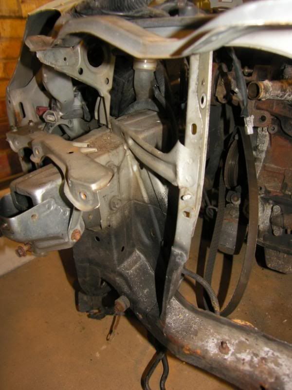
I used the spot weld drill, a pry bar and the angle grinder detach the pressings
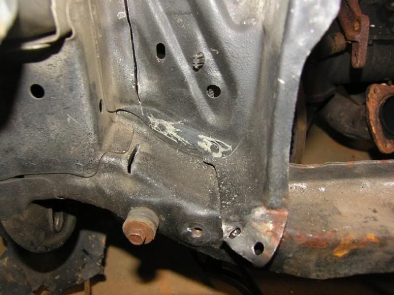

A little bit of hacksaw action to some places inaccessible to the angle grinder
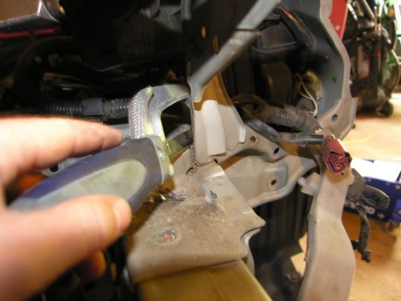
And it all came off -
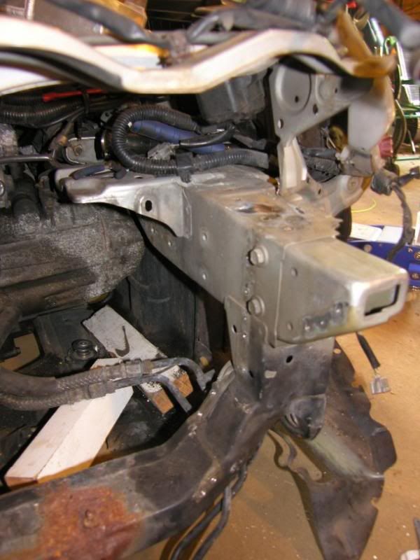
After a bit of tidying with the flap disc -
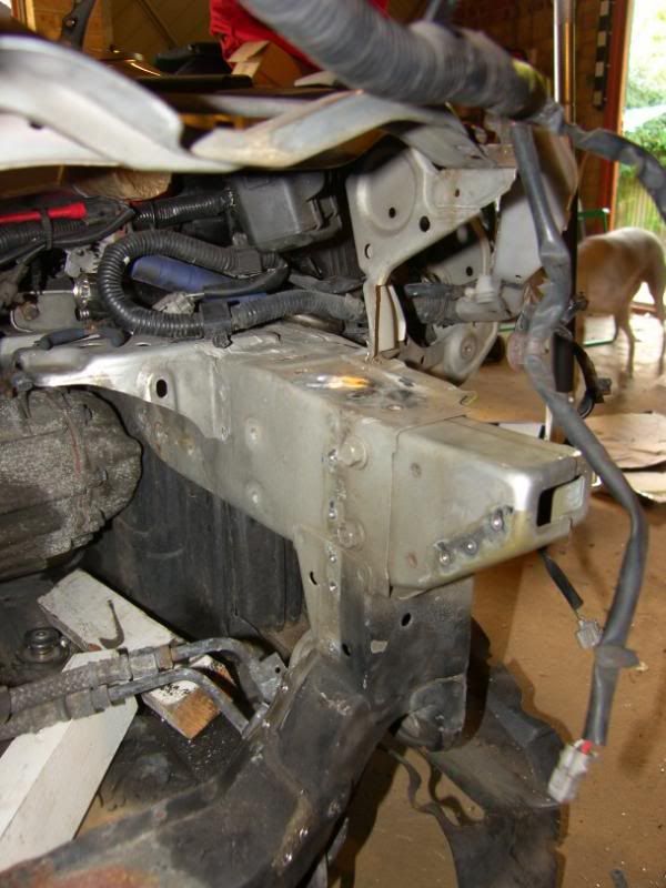
Rinse and repeat for the other side and then try the rads for size
I started to think about fans and placing of the rads, I want them to be as far back as possible but still have a fan. After a bit of rooting around in the garage I found the pusher fan I used on the supercharged imp, put it on the rad and it was perfect!
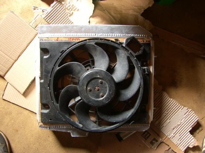
Even fits well in the front of the car!
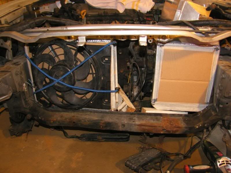
I then decided to start making up a mould for slightly better fitting fan cowl, out came the insulation foam! -
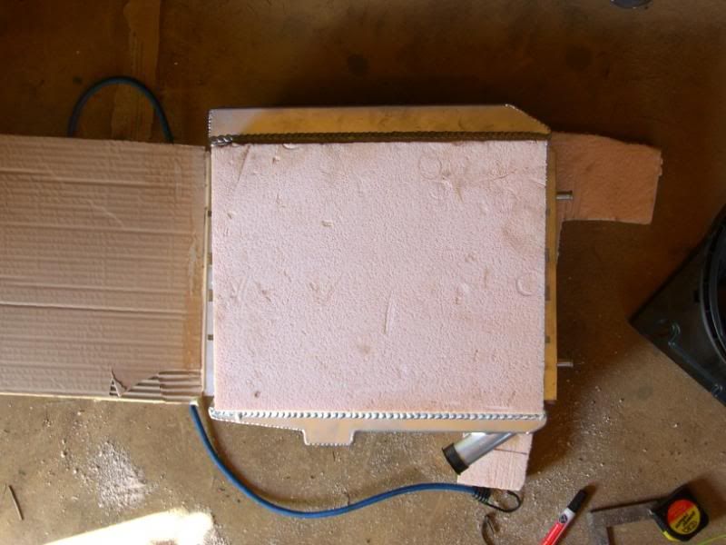
The fan traced onto the surface -
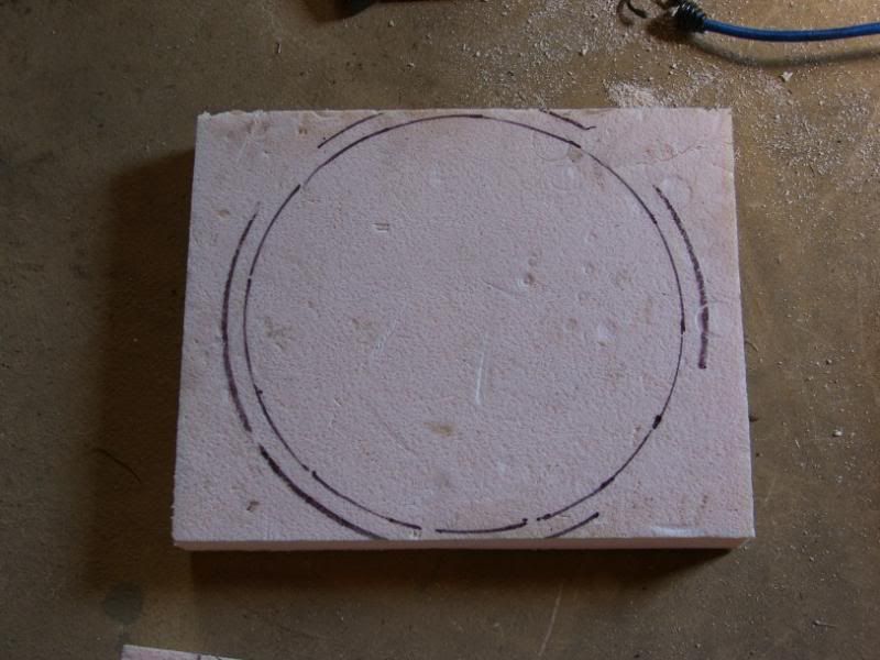
Rough cut -
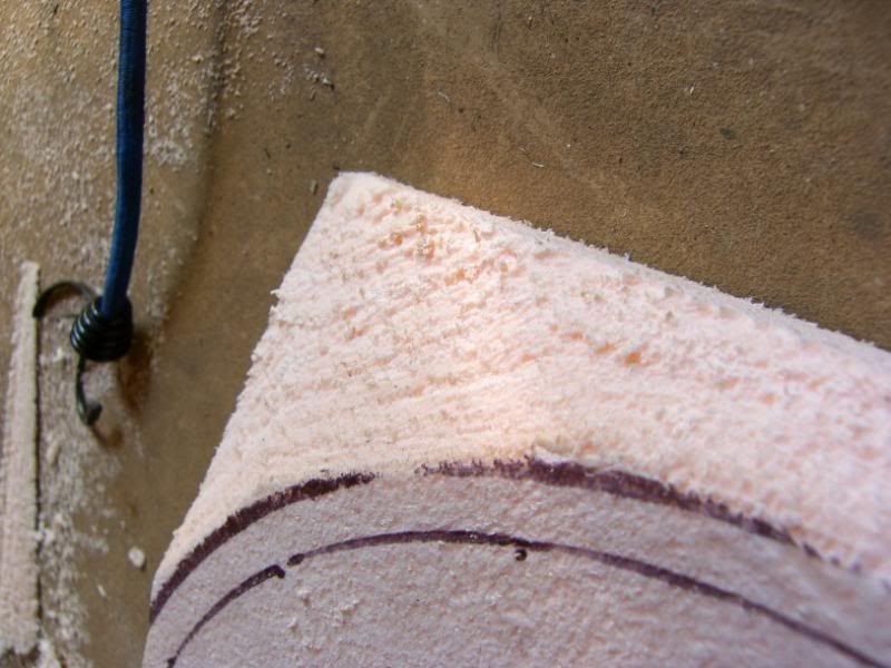
Some sanding -
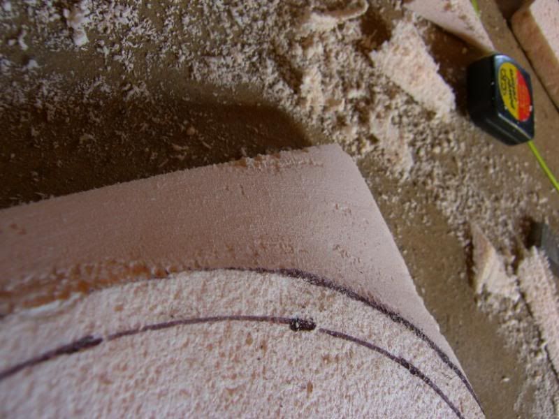
And there she is! -
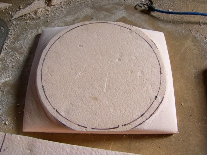
This will be covered in release agent and then laid up with epoxy and glass then carbon for the top skin
I have all the bits to make the exhaust manifold on their way, so that should be our next installment
Thats it for now, more soon!
J
Bit of an update today, I got brave!
First off though, I finally managed to set up my garage PC
So I now spend a lot less time running in and out, and it is safer than having the laptop on my workbench
Now for the brave bit, as you know I have been a bit tight on space for the cooling pack and I also want to replace the front cross member. The solution to my problems? Get choppy
These are the normal pressings that surround the rad / headlight assembly -
I used the spot weld drill, a pry bar and the angle grinder detach the pressings
A little bit of hacksaw action to some places inaccessible to the angle grinder
And it all came off -
After a bit of tidying with the flap disc -
Rinse and repeat for the other side and then try the rads for size
I started to think about fans and placing of the rads, I want them to be as far back as possible but still have a fan. After a bit of rooting around in the garage I found the pusher fan I used on the supercharged imp, put it on the rad and it was perfect!
Even fits well in the front of the car!
I then decided to start making up a mould for slightly better fitting fan cowl, out came the insulation foam! -
The fan traced onto the surface -
Rough cut -
Some sanding -
And there she is! -
This will be covered in release agent and then laid up with epoxy and glass then carbon for the top skin
I have all the bits to make the exhaust manifold on their way, so that should be our next installment
Thats it for now, more soon!
J
Gassing Station | Readers' Cars | Top of Page | What's New | My Stuff