Discussion


I had a thread up in the home mechanics forum regarding a specific tool and after describing what I had been up to duly said that I would post a few words and some pictures detailing what I’d been up to with the Tuscan.. Usually people post as they go along, but as time was tight with other commitments I’ve made this a retrospective form of write up. It may need delivering in a few parts!
This is the story of a TVR Tuscan, running one and being hands on with one. I’ve posted this here as many folk on the TVR forum will pour scorn and insist it’s a highly toleranced beast that needs the fettling of a TVR magician. It couldn’t possibly be looked after by a mortal in a home garage.
It is a story of an enthusiast having a go, getting involved and getting closer to the car, and developing a better understanding of it. Making new friends along the way, but still getting help from old ones ?.
Some of you will read this thinking this is the sort of thing I want to get my hands on, others will look at it as warning of what can happen… and this is a relatively good example of a Tuscan! And be warned if you scan the Tuscan forum closely enough for experiences you will find far, far worse.
Sit back, put your feet up, get a beer and enjoy the tale!
And before any TVR fanatics get their pants in a knot, these are simply my conclusions from the investigations I performed. They may be right they may be wrong… but they are what I have chosen to do being a risk adverse kind of chap!
Background
I bought this car in 2011, from a very nice couple near st neots. I’d been looking for some time. I wanted a car that could be a project car. Preferably not too much engine work required but maybe some tidying, suspension interior etc.
After looking at a number of cars described as “immaculate” (by what I can only assume were magic mushroom abusers), I happened upon this car. A late 2001 Tuscan 4.0L. Ideally I wanted a car that had at least received a top end rebuild (explanation to come) and didn’t have enough water in it to be an aquarium. This car had, had what I had assumed was a top end rebuild the cams and followers replaced with what many regard as the leading and highest profile TVR specialist’s cams and followers. So I had confidence that the top end would be fine, it didn’t smoke, or over heat and the chap selling it said it used very little oil. It came with its original invoice and a folder of bills big enough to buy an entry level BMW. It had every single extra specified from Air con, Hydrtrack LSD, wool carpets in the boot, and above all I had a good feeling about the car and the chap selling it.
I took the train from Kings Cross one Friday after work up to St Neots and the deal was done and I was on my way home to Kent.
Why a Tuscan of all things!
I really wanted to build an Ultima GTR but I didn’t really have the time (4 dogs, wife etc) it would never get finished. I could have bought one but I wanted one with an LS7 and those were still commanding good money. I’d had a Porsche, it was great! Never went wrong, but just seemed a bit dull.
I’d also built a Peugeot 205 MI16 by ripping the engine and management system from a 405 MI16 and putting it into the 205. I enjoyed that as I like being hands on but those were more electrical challenges transferring the management system and putting a new loom together, with a few fabrication challenges on the way.
Shortly before I bought the Tuscan I bought a VR6 engine, which I was going to Turbo charge, but to get the 500 bhp I was looking for was going to require some serious parts investment so came to my senses and sold it all on.
Something that would go like this….
I came to the conclusion that the half way house, which would give buckets of performance and give me plenty to tinker with was a TVR!
I tried Cerebra’s but I’m fairly wide, and they just felt like driving around in coffins with their very square transmission tunnel.
Then one day I went to TAG11 – TVR’s at GoodWood 2011. There I saw Tuscans and Sagaris going round on track. I heard the speed six sound track and was hooked. In particular one car got my attention a navy blue Tuscan, which was Racing Green TVRs demonstrator and went like the clappers.
The Early Days..
I bought the car with the mindset that I’d track it with my Dad. He was a biker and loved the way the speed six revved up. He had recently been diagnosed with cancer and wasn’t in the right place to drive it, so got me to give him the biking fix and take him out in the Tuscan. He would urge me to boot it at every opportunity far harder than I was willing to on the public highway, giving him the feeling that he enjoyed on the bikes. He never did get to track the car, but I had some good memories taking him out in it during his last few months so the car took on a new type of sentimental value to me. It was here to stay…
Within 2 months of having the car the fantastic servicing by the previous garage shone through.. not!
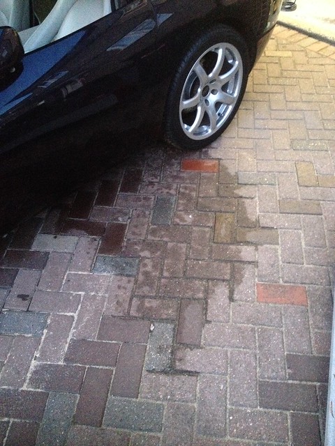
Reversing into the driveway a jubilee clip let go between the rad to oil cooler hose. After shutting her down and investigating I saw the offending jubilee clip split in half. I went to remove it only to receive a cut to my index finger. Within 4 days I would be in hospital with an infection tracking up my arm to my heart.. you could physically see the red line going up the vein in my forearm, through my upper arm, and up to my neck. After intravenous anti biotics, and a short stay in hospital I was back on my feet.. but realised you didn’t even need to drive TVR for it to kill you.
And this was a car with 10’s of thousands of pounds worth of bills.. Seriously.
In the first year I did a 12k mile service on it including valve clearances and everything seemed fine, it pulled like a train (albeit one that sounded like it was about to explode) and would show most things it encountered on the road its shrinking rear number plate.
Due to work etc I only did about 1500 miles a year over the first two years. Plus my wife hated driving in it.
In mid to late 2013 I noticed that the oil was being used more frequently than I anticipated.. to the tune of 300 miles a litre. Something wasn’t quite right.
Problems..
So in November 2013 I set about diagnosing this sudden hunger for oil. I did a compression test and all of the cylinders had cracking compression, but two were higher than the others. Reviewing the spark plugs the cylinders with the most compression were also those with the blackest, wettest, fouled spark plugs.
There was obviously valve guide/seal related issues on the rear two cylinders. I was 99% sure it was this. The car demonstrated all the classic symptoms, occasional smokey hot start and if blipping the throttle having sat in traffic (oil at its thinnest) a puff of blue smoke would come from the exhaust.
But how could this be, the car had a top end rebuild in 2010.. I carefully went through all the bills and whilst they had the engine out doing investigating the top end tick the garage in question simply replaced the cams and followers with the latest spec higher quality products. They touched nothing else. Genius!
At this point having confirmed a few things and being confident of the issue I started looking around at parts suppliers and discussing requirements with them.
The Inherent speed six problem – a brief summary:
The head consist of 24 valves, consisting of 24 finger followers actuating valves as the cam shaft lobe drives the follower.
Its fairly widely known that the majority of the speed six engine issues from the early days were caused by components being manufactured using processes/materials which were simply not fit for purpose. Cams and followers were the primary cause, as the case hardening failed so did the cams and followers allowing metallic debris to move through the engine.
The performance parts power house that is “India” was used to manufacture some of the early parts… and we all know that only the highest quality engine parts come from India (in case your reading this and believing it.. this is pure jest..they don’t)
Some said it was TVR’s meddling with the original Al Melling design causing poor oil flow to the rear of the head and thus poor lubrication to the rear of the head… But then as rumour has it TVR ran the heads submerged in oil, and still there were valve train failures.
In my research having spoken to several leading experts one of which, had engineers reviews conducted on the design, it became apparent that there was more than simply lubrication problems. The reports essentially revealed that the geometry in the head would always result in some form of cam and follower wear regardless of material used (interesting pics to follow). Add to this, that there was also the rumour that the head castings weren’t the greatest quality and in some cases “were off” contributing to the valve train geometry problem, I had some thinking to do.
The Solution..
After ringing around and speaking to various suppliers I decided to use Racing green TVR. They weren’t a million miles away and could supply me all the parts I needed to rebuild the head as is using some of the best component suppliers in the world. Above all their MD Colin was willing to spend significant time on the phone with me taking me through all of the options available.
Initially the “as is” refurb is what I had in mind. Use the highest quality parts and refurbish the head. There was a nagging doubt in my mind about this strategy that due to some of the problems outlined above this could be a lottery. It could last 10k miles or 100k miles a lot would depend on a specific head casting. I wanted to eliminate that risk.
Racing Green had another solution though… to me this was the ultimate solution to the head “issues” the triple “f” – FFF which stands for “Finger follower Free.
That’s right.. no finger followers, in the hey day of speed six head issues they went their own way commissioning a new head design, which removed the finger followers and replaced them with buckets. This original design has evolved in to what it is now, the FFF2 and this is what I went for.
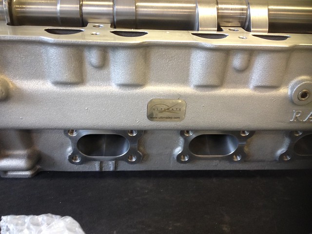
The FFF 2 is manufactured for Racing Green by Simon Armstrong of ultimate performance. Simon is well known in the performance world and has a F1 engineering back ground.
http://www.ultimatep.co.uk/shopinfo_company_backgr...
Each FFF2 is CnC machined by Simon and is simply a work of art. As well removing any inherent design issues, the FFF2 head, due to its evolved and highly accurate manufacturing process also delivers a power increase.
It was a lot more money than the simple head refurb but would give me piece of mind and a bit of a performance hike.
On top of all this it is completely interchangeable with the standard head.
Oh and there was the thought of it being able to produce this sort of power …..
http://www.pistonheads.com/gassing/topic.asp?h=3&a...
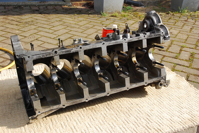
Decisions made- time to pull it apart:
Removing the Engine… Easy peasy (Not)
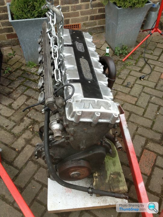
Once the decision was made to rebuild the engine I set about removing it. Fortunately I have a scissor lift type ramp in my garage. I decided I would drop the engine from below, onto a skid, which I made up from an old work top bought from a charity shop and a set of castors I found in my dads garage (he was a bit of a hoarder and I’d always shake my head wondering why he saved all this stuff but bizarrely these came in bloody handy).
Theres no magic to this, but it is a fairly length job. Everything needs to come off, Exhaust, prop shaft, gearbox plus lots of smaller parts. I had my best mate Mark helping me do the engine removal. It took us about 3 whole weekends of Sunday’s and I soon understood why specialist wanted about £1 – 1.5k to remove and refit the engine. In reality it was probably 2 Sundays doing and 1 staring at it with stellas in hand ?
The engine is canted over about 10 – 15 degrees. For it to clear the chassis it essentially needs pushing in the opposite direction… but its not as simple as you think virtually ever ancillary needs to come off to clear the chassis rails.. power steering pump, alternator, air con compressor, plus all of the oil hose which appeared to have never been touched so were seized in place.
We spent nearly a whole weekend scratching our heads as no matter what way we tilted the engine it wouldn’t clear the chassis rails. Many Stella breaks were taken at this point but with little inspiration.
After studying the engine some more whilst drinking one of the magical Stella’s it was clear that the only thing preventing the engine from being removed was the Aircon pulley. The air conditioning compressor is driven by a pulley from the Auxillary shaft located below the compressor. The pulley on the end of the auxiliary shaft sits tightly between the crank damper (literally 1.5mm ‘s from it) and the timing cover. The exposed end of the auxillary shaft was located at least 5 mm inside the pulley.. It looked impossible to remove, but sure enough after removing all of the locating screws and persuading it with a club hammer it was possible to knock it at an angle and clear the damper.. The things you wish you’d known before starting a job.
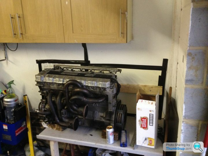
The ramp played a major part in the engine removal and it would be a pretty serious job to attempt without one. I have an engine crane, but you would need a seriously robust one with a long lifting arm on it as the engine is set a long way back and is physically long in dimensions. We did look at using the crane but when going to lift, it simply wanted to move forward and munch through the service bonnet..
One big hurdle out the way, and the engine was on the bench.
This is the story of a TVR Tuscan, running one and being hands on with one. I’ve posted this here as many folk on the TVR forum will pour scorn and insist it’s a highly toleranced beast that needs the fettling of a TVR magician. It couldn’t possibly be looked after by a mortal in a home garage.
It is a story of an enthusiast having a go, getting involved and getting closer to the car, and developing a better understanding of it. Making new friends along the way, but still getting help from old ones ?.
Some of you will read this thinking this is the sort of thing I want to get my hands on, others will look at it as warning of what can happen… and this is a relatively good example of a Tuscan! And be warned if you scan the Tuscan forum closely enough for experiences you will find far, far worse.
Sit back, put your feet up, get a beer and enjoy the tale!
And before any TVR fanatics get their pants in a knot, these are simply my conclusions from the investigations I performed. They may be right they may be wrong… but they are what I have chosen to do being a risk adverse kind of chap!
Background
I bought this car in 2011, from a very nice couple near st neots. I’d been looking for some time. I wanted a car that could be a project car. Preferably not too much engine work required but maybe some tidying, suspension interior etc.
After looking at a number of cars described as “immaculate” (by what I can only assume were magic mushroom abusers), I happened upon this car. A late 2001 Tuscan 4.0L. Ideally I wanted a car that had at least received a top end rebuild (explanation to come) and didn’t have enough water in it to be an aquarium. This car had, had what I had assumed was a top end rebuild the cams and followers replaced with what many regard as the leading and highest profile TVR specialist’s cams and followers. So I had confidence that the top end would be fine, it didn’t smoke, or over heat and the chap selling it said it used very little oil. It came with its original invoice and a folder of bills big enough to buy an entry level BMW. It had every single extra specified from Air con, Hydrtrack LSD, wool carpets in the boot, and above all I had a good feeling about the car and the chap selling it.
I took the train from Kings Cross one Friday after work up to St Neots and the deal was done and I was on my way home to Kent.
Why a Tuscan of all things!
I really wanted to build an Ultima GTR but I didn’t really have the time (4 dogs, wife etc) it would never get finished. I could have bought one but I wanted one with an LS7 and those were still commanding good money. I’d had a Porsche, it was great! Never went wrong, but just seemed a bit dull.
I’d also built a Peugeot 205 MI16 by ripping the engine and management system from a 405 MI16 and putting it into the 205. I enjoyed that as I like being hands on but those were more electrical challenges transferring the management system and putting a new loom together, with a few fabrication challenges on the way.
Shortly before I bought the Tuscan I bought a VR6 engine, which I was going to Turbo charge, but to get the 500 bhp I was looking for was going to require some serious parts investment so came to my senses and sold it all on.
Something that would go like this….
I came to the conclusion that the half way house, which would give buckets of performance and give me plenty to tinker with was a TVR!
I tried Cerebra’s but I’m fairly wide, and they just felt like driving around in coffins with their very square transmission tunnel.
Then one day I went to TAG11 – TVR’s at GoodWood 2011. There I saw Tuscans and Sagaris going round on track. I heard the speed six sound track and was hooked. In particular one car got my attention a navy blue Tuscan, which was Racing Green TVRs demonstrator and went like the clappers.
The Early Days..
I bought the car with the mindset that I’d track it with my Dad. He was a biker and loved the way the speed six revved up. He had recently been diagnosed with cancer and wasn’t in the right place to drive it, so got me to give him the biking fix and take him out in the Tuscan. He would urge me to boot it at every opportunity far harder than I was willing to on the public highway, giving him the feeling that he enjoyed on the bikes. He never did get to track the car, but I had some good memories taking him out in it during his last few months so the car took on a new type of sentimental value to me. It was here to stay…
Within 2 months of having the car the fantastic servicing by the previous garage shone through.. not!
Reversing into the driveway a jubilee clip let go between the rad to oil cooler hose. After shutting her down and investigating I saw the offending jubilee clip split in half. I went to remove it only to receive a cut to my index finger. Within 4 days I would be in hospital with an infection tracking up my arm to my heart.. you could physically see the red line going up the vein in my forearm, through my upper arm, and up to my neck. After intravenous anti biotics, and a short stay in hospital I was back on my feet.. but realised you didn’t even need to drive TVR for it to kill you.
And this was a car with 10’s of thousands of pounds worth of bills.. Seriously.
In the first year I did a 12k mile service on it including valve clearances and everything seemed fine, it pulled like a train (albeit one that sounded like it was about to explode) and would show most things it encountered on the road its shrinking rear number plate.
Due to work etc I only did about 1500 miles a year over the first two years. Plus my wife hated driving in it.
In mid to late 2013 I noticed that the oil was being used more frequently than I anticipated.. to the tune of 300 miles a litre. Something wasn’t quite right.
Problems..
So in November 2013 I set about diagnosing this sudden hunger for oil. I did a compression test and all of the cylinders had cracking compression, but two were higher than the others. Reviewing the spark plugs the cylinders with the most compression were also those with the blackest, wettest, fouled spark plugs.
There was obviously valve guide/seal related issues on the rear two cylinders. I was 99% sure it was this. The car demonstrated all the classic symptoms, occasional smokey hot start and if blipping the throttle having sat in traffic (oil at its thinnest) a puff of blue smoke would come from the exhaust.
But how could this be, the car had a top end rebuild in 2010.. I carefully went through all the bills and whilst they had the engine out doing investigating the top end tick the garage in question simply replaced the cams and followers with the latest spec higher quality products. They touched nothing else. Genius!
At this point having confirmed a few things and being confident of the issue I started looking around at parts suppliers and discussing requirements with them.
The Inherent speed six problem – a brief summary:
The head consist of 24 valves, consisting of 24 finger followers actuating valves as the cam shaft lobe drives the follower.
Its fairly widely known that the majority of the speed six engine issues from the early days were caused by components being manufactured using processes/materials which were simply not fit for purpose. Cams and followers were the primary cause, as the case hardening failed so did the cams and followers allowing metallic debris to move through the engine.
The performance parts power house that is “India” was used to manufacture some of the early parts… and we all know that only the highest quality engine parts come from India (in case your reading this and believing it.. this is pure jest..they don’t)
Some said it was TVR’s meddling with the original Al Melling design causing poor oil flow to the rear of the head and thus poor lubrication to the rear of the head… But then as rumour has it TVR ran the heads submerged in oil, and still there were valve train failures.
In my research having spoken to several leading experts one of which, had engineers reviews conducted on the design, it became apparent that there was more than simply lubrication problems. The reports essentially revealed that the geometry in the head would always result in some form of cam and follower wear regardless of material used (interesting pics to follow). Add to this, that there was also the rumour that the head castings weren’t the greatest quality and in some cases “were off” contributing to the valve train geometry problem, I had some thinking to do.
The Solution..
After ringing around and speaking to various suppliers I decided to use Racing green TVR. They weren’t a million miles away and could supply me all the parts I needed to rebuild the head as is using some of the best component suppliers in the world. Above all their MD Colin was willing to spend significant time on the phone with me taking me through all of the options available.
Initially the “as is” refurb is what I had in mind. Use the highest quality parts and refurbish the head. There was a nagging doubt in my mind about this strategy that due to some of the problems outlined above this could be a lottery. It could last 10k miles or 100k miles a lot would depend on a specific head casting. I wanted to eliminate that risk.
Racing Green had another solution though… to me this was the ultimate solution to the head “issues” the triple “f” – FFF which stands for “Finger follower Free.
That’s right.. no finger followers, in the hey day of speed six head issues they went their own way commissioning a new head design, which removed the finger followers and replaced them with buckets. This original design has evolved in to what it is now, the FFF2 and this is what I went for.
The FFF 2 is manufactured for Racing Green by Simon Armstrong of ultimate performance. Simon is well known in the performance world and has a F1 engineering back ground.
http://www.ultimatep.co.uk/shopinfo_company_backgr...
Each FFF2 is CnC machined by Simon and is simply a work of art. As well removing any inherent design issues, the FFF2 head, due to its evolved and highly accurate manufacturing process also delivers a power increase.
It was a lot more money than the simple head refurb but would give me piece of mind and a bit of a performance hike.
On top of all this it is completely interchangeable with the standard head.
Oh and there was the thought of it being able to produce this sort of power …..
http://www.pistonheads.com/gassing/topic.asp?h=3&a...
Decisions made- time to pull it apart:
Removing the Engine… Easy peasy (Not)
Once the decision was made to rebuild the engine I set about removing it. Fortunately I have a scissor lift type ramp in my garage. I decided I would drop the engine from below, onto a skid, which I made up from an old work top bought from a charity shop and a set of castors I found in my dads garage (he was a bit of a hoarder and I’d always shake my head wondering why he saved all this stuff but bizarrely these came in bloody handy).
Theres no magic to this, but it is a fairly length job. Everything needs to come off, Exhaust, prop shaft, gearbox plus lots of smaller parts. I had my best mate Mark helping me do the engine removal. It took us about 3 whole weekends of Sunday’s and I soon understood why specialist wanted about £1 – 1.5k to remove and refit the engine. In reality it was probably 2 Sundays doing and 1 staring at it with stellas in hand ?
The engine is canted over about 10 – 15 degrees. For it to clear the chassis it essentially needs pushing in the opposite direction… but its not as simple as you think virtually ever ancillary needs to come off to clear the chassis rails.. power steering pump, alternator, air con compressor, plus all of the oil hose which appeared to have never been touched so were seized in place.
We spent nearly a whole weekend scratching our heads as no matter what way we tilted the engine it wouldn’t clear the chassis rails. Many Stella breaks were taken at this point but with little inspiration.
After studying the engine some more whilst drinking one of the magical Stella’s it was clear that the only thing preventing the engine from being removed was the Aircon pulley. The air conditioning compressor is driven by a pulley from the Auxillary shaft located below the compressor. The pulley on the end of the auxiliary shaft sits tightly between the crank damper (literally 1.5mm ‘s from it) and the timing cover. The exposed end of the auxillary shaft was located at least 5 mm inside the pulley.. It looked impossible to remove, but sure enough after removing all of the locating screws and persuading it with a club hammer it was possible to knock it at an angle and clear the damper.. The things you wish you’d known before starting a job.
The ramp played a major part in the engine removal and it would be a pretty serious job to attempt without one. I have an engine crane, but you would need a seriously robust one with a long lifting arm on it as the engine is set a long way back and is physically long in dimensions. We did look at using the crane but when going to lift, it simply wanted to move forward and munch through the service bonnet..
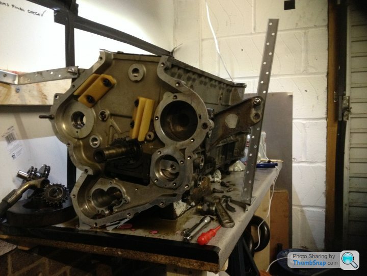
One big hurdle out the way, and the engine was on the bench.
Edited by m4tti on Monday 27th October 12:18
Part two...
In process of removing the engine there was the odd nice surprise.. I did find that there was an Race Proved slave cylinder fitted, which typically don’t fail so randomly or frequently and it also saved me buying one at £350.

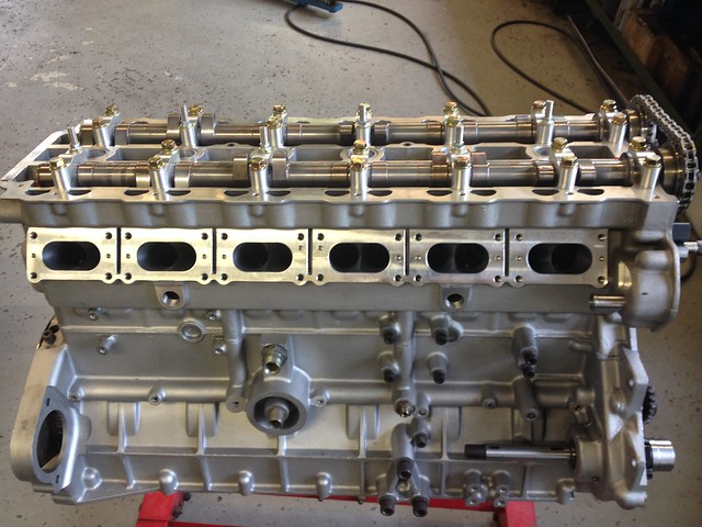
Stripping it down
I spent the next couple of weekends systematically pulling the engine apart and putting parts into zip lock bags and labelling them accordingly, and taking pictures.
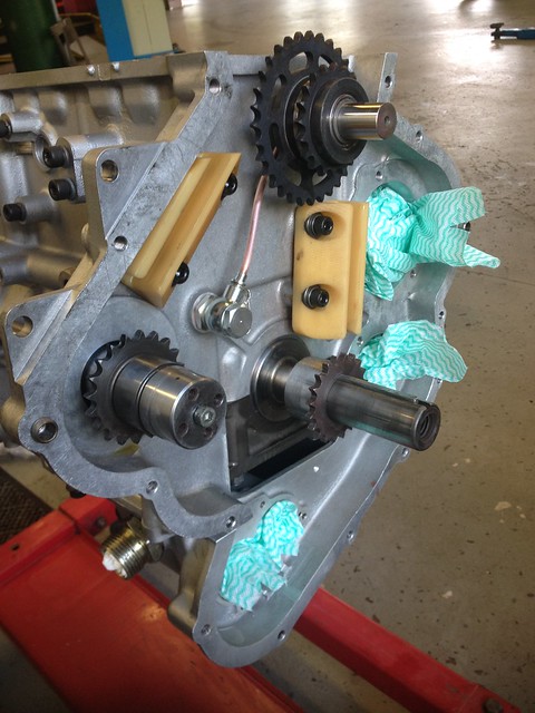
Again there was nothing particularly difficult at this stage. The crank damper seemed to have rusted nicely in place and trashed the harmonic damper removing tool I had.. it came off eventually with a 4 legged gear puller. Once removed the timing cover could come off exposing the timing chains, oil pumps and water pump.
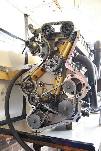
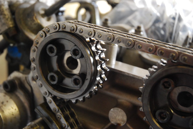
Here you can clearly see the duplex chains (these would be going)
Measuring the existing timing
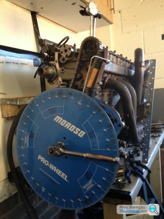
The speed six has absolutely no timing marks on it. You need a degree wheel and a DTI. Acquiring a large timing wheel in this country seem s almost impossible these days so I had a moroso degree wheel imported from the states. The larger the wheel the easier it is.
 DSC_0092 by Barkley Dogue, on Flickr
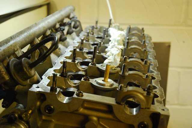
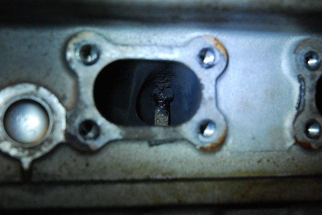
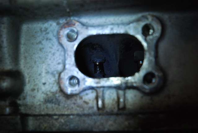
I slowly chugged through it and eventually got the head off. Once the head was removed it became clear what the issue was. Looking in several of the inlet and exhaust ports oil was evident on the valve stems. Reaching into the ports I could physically wiggle the valves in the guides! No wonder it was using oil.
In fact the majority of the guides were fubar'd
 DSC_0089 by Barkley Dogue, on Flickr
 DSC_0085 by Barkley Dogue, on Flickr
 DSC_0091 by Barkley Dogue, on Flickr
This is at 39k miles!!
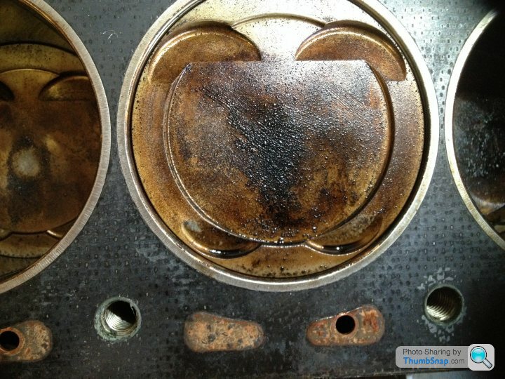
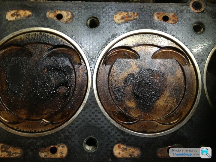
There was plenty of oil on top of the pistons too.. it was collecting in the valve pockets!! At least the pistons wouldnt get stuck in the bores.
Bit like an oil BBQ..
In process of removing the engine there was the odd nice surprise.. I did find that there was an Race Proved slave cylinder fitted, which typically don’t fail so randomly or frequently and it also saved me buying one at £350.
Stripping it down
I spent the next couple of weekends systematically pulling the engine apart and putting parts into zip lock bags and labelling them accordingly, and taking pictures.
Again there was nothing particularly difficult at this stage. The crank damper seemed to have rusted nicely in place and trashed the harmonic damper removing tool I had.. it came off eventually with a 4 legged gear puller. Once removed the timing cover could come off exposing the timing chains, oil pumps and water pump.
Here you can clearly see the duplex chains (these would be going)
Measuring the existing timing
The speed six has absolutely no timing marks on it. You need a degree wheel and a DTI. Acquiring a large timing wheel in this country seem s almost impossible these days so I had a moroso degree wheel imported from the states. The larger the wheel the easier it is.
DSC_0092 by Barkley Dogue, on FlickrI slowly chugged through it and eventually got the head off. Once the head was removed it became clear what the issue was. Looking in several of the inlet and exhaust ports oil was evident on the valve stems. Reaching into the ports I could physically wiggle the valves in the guides! No wonder it was using oil.
In fact the majority of the guides were fubar'd
DSC_0089 by Barkley Dogue, on FlickrDSC_0085 by Barkley Dogue, on FlickrDSC_0091 by Barkley Dogue, on FlickrThis is at 39k miles!!
There was plenty of oil on top of the pistons too.. it was collecting in the valve pockets!! At least the pistons wouldnt get stuck in the bores.
Bit like an oil BBQ..
Edited by m4tti on Sunday 5th October 20:05
Part 3.. The strip Down Continues
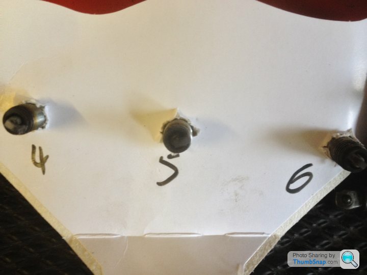
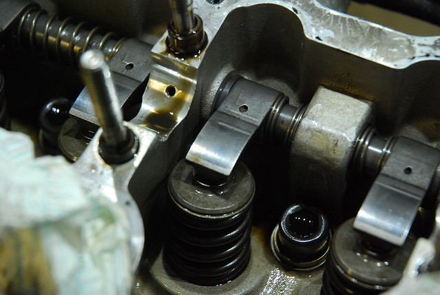
Stripping the head some more revealed more interesting (ish) evidence on its health. The cams looked all good, and the majority of the followers were ok… but as you reached the rear followers evidence of wear was visible. You could feel this wear when running your finger nail over it. When I first visited Colin the MD of Racing green I had said that I couldn't see any wear when I did the last tappet service, he'd said Id really need to remove the cams to see it and sure enough it was there, albeit in an early phase..
Front cylinder followers.. nothing too awful
 DSC_0098 by Barkley Dogue, on Flickr
and again..
 DSC_0103 by Barkley Dogue, on Flickr
Very faint markings laterally across this follower..
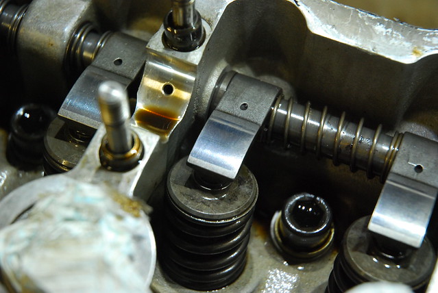 DSC_0105 by Barkley Dogue, on Flickr
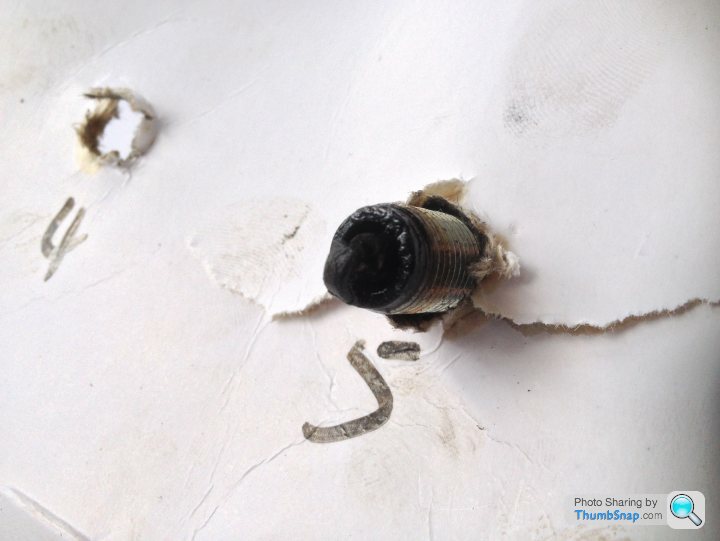
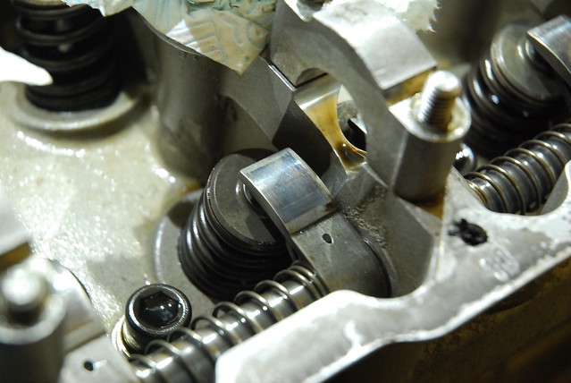
Rear cylinders, markings clearly visible, almost scoring type of wear.
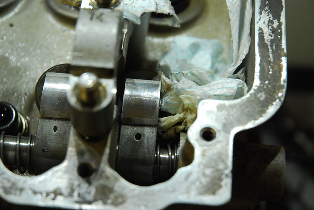 DSC_0095 by Barkley Dogue, on Flickr
Bear in mind these followers are almost in-accessible in situ as the engine is mounted a long way back, front mid. The last two followers sit under the windscreen. Essentially you wouldn't know this until you are this far.
Remember these had been replaced 10k miles ago with the latest cams and followers. Was it poor lubrication to the rear of the head or was it the geometry problems… who knows, but having got this far it confirmed in my head that the Racing Green FFF was the right long term solution.
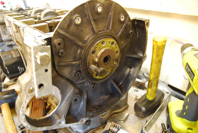
A bit more work and I'm close to revealing the bottom end. The sacavenge pump is mounted in the sump, and both the sump and crank end plate are RTF'd in place. Careful patient removal is the order of the day. Levering things ends in broken ally engine parts. That's a pretend club hanner in the picture
 DSC_0109 by Barkley Dogue, on Flickr
Sumps off..
 DSC_0111 by Barkley Dogue, on Flickr
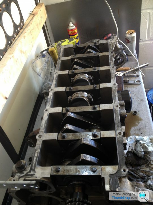
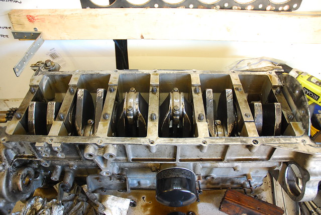
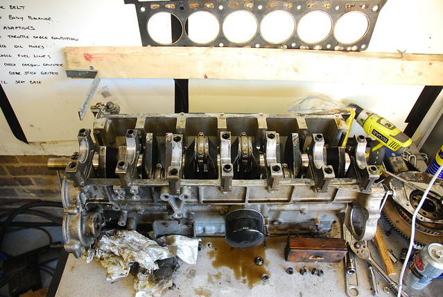
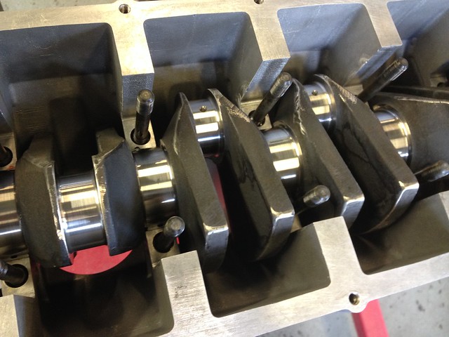
And we're there.. main bearing caps pulled. Time to have a look whats going on
 DSC_0114 by Barkley Dogue, on Flickr
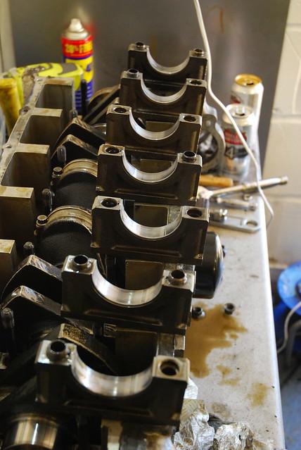 DSC_0125 by Barkley Dogue, on Flickr
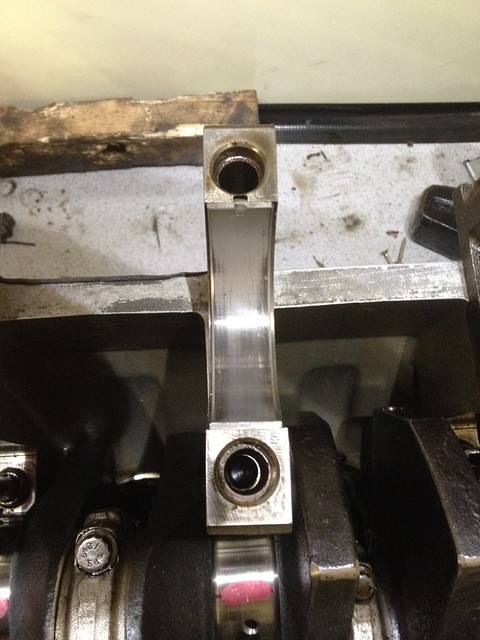
Once I was down to just block and crank I measured up the big end clearances and measured the end float. All looked in spec so I was relatively happy with the state of the bottom end. The bearings themselves looked reasonable in terms of wear, but there were some signs of metal having entered the oil system as there was some light scoring. The metal entering the oil system would have occured when the original TVR cams and followers failed (remember these have already been replaced)
 IMG_0994 by Barkley Dogue, on Flickr
 IMG_0993 by Barkley Dogue, on Flickr
 IMG_0992 by Barkley Dogue, on Flickr
 IMG_0991 by Barkley Dogue, on Flickr
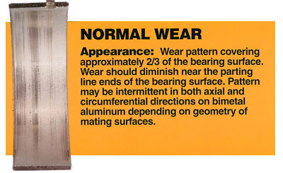
And as a benchmark for those who are interested here's the a normal wear pattern..
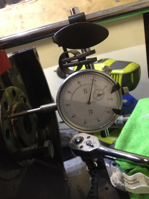
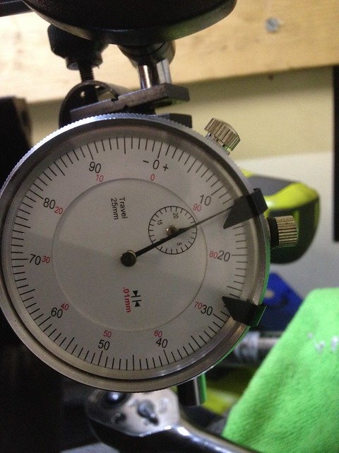
End float...acceptable
 IMG_1002 by Barkley Dogue, on Flickr
 IMG_1003 by Barkley Dogue, on Flickr
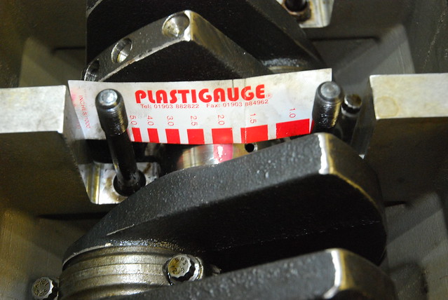
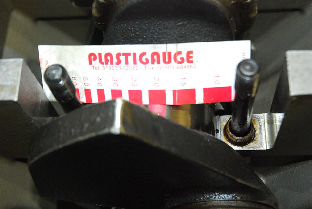
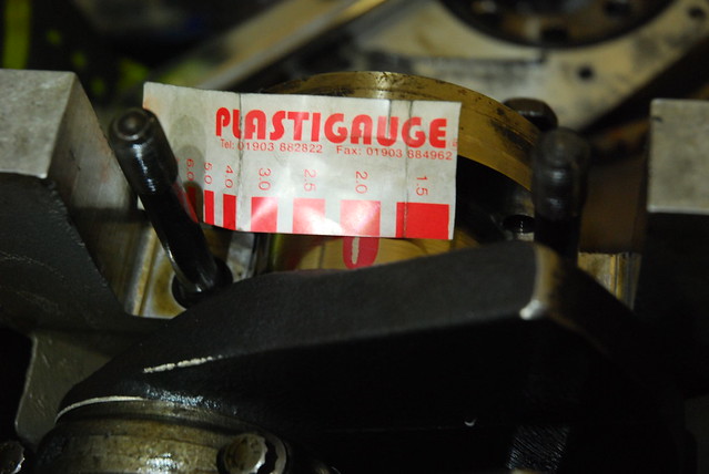
I measured the big end clearances using plastigauge, which although not the ultimate in measuring equipment it was fine for what I was doing, and in fact as I had the crank measured to determine whether it was out of round (more on this later), which it wasn’t, which provided more confidence in the measurements.
 DSC_0131 by Barkley Dogue, on Flickr
 DSC_0135 by Barkley Dogue, on Flickr
 DSC_0144 by Barkley Dogue, on Flickr
So, I'm reasonably happy at this stage.. but there's more surprises to come!!
Stripping the head some more revealed more interesting (ish) evidence on its health. The cams looked all good, and the majority of the followers were ok… but as you reached the rear followers evidence of wear was visible. You could feel this wear when running your finger nail over it. When I first visited Colin the MD of Racing green I had said that I couldn't see any wear when I did the last tappet service, he'd said Id really need to remove the cams to see it and sure enough it was there, albeit in an early phase..
Front cylinder followers.. nothing too awful
DSC_0098 by Barkley Dogue, on Flickrand again..
DSC_0103 by Barkley Dogue, on FlickrVery faint markings laterally across this follower..
DSC_0105 by Barkley Dogue, on FlickrRear cylinders, markings clearly visible, almost scoring type of wear.
DSC_0095 by Barkley Dogue, on FlickrBear in mind these followers are almost in-accessible in situ as the engine is mounted a long way back, front mid. The last two followers sit under the windscreen. Essentially you wouldn't know this until you are this far.
Remember these had been replaced 10k miles ago with the latest cams and followers. Was it poor lubrication to the rear of the head or was it the geometry problems… who knows, but having got this far it confirmed in my head that the Racing Green FFF was the right long term solution.
A bit more work and I'm close to revealing the bottom end. The sacavenge pump is mounted in the sump, and both the sump and crank end plate are RTF'd in place. Careful patient removal is the order of the day. Levering things ends in broken ally engine parts. That's a pretend club hanner in the picture
DSC_0109 by Barkley Dogue, on FlickrSumps off..
DSC_0111 by Barkley Dogue, on FlickrAnd we're there.. main bearing caps pulled. Time to have a look whats going on
DSC_0114 by Barkley Dogue, on FlickrDSC_0125 by Barkley Dogue, on FlickrOnce I was down to just block and crank I measured up the big end clearances and measured the end float. All looked in spec so I was relatively happy with the state of the bottom end. The bearings themselves looked reasonable in terms of wear, but there were some signs of metal having entered the oil system as there was some light scoring. The metal entering the oil system would have occured when the original TVR cams and followers failed (remember these have already been replaced)
IMG_0994 by Barkley Dogue, on FlickrIMG_0993 by Barkley Dogue, on FlickrIMG_0992 by Barkley Dogue, on FlickrIMG_0991 by Barkley Dogue, on FlickrAnd as a benchmark for those who are interested here's the a normal wear pattern..
End float...acceptable
IMG_1002 by Barkley Dogue, on FlickrIMG_1003 by Barkley Dogue, on FlickrI measured the big end clearances using plastigauge, which although not the ultimate in measuring equipment it was fine for what I was doing, and in fact as I had the crank measured to determine whether it was out of round (more on this later), which it wasn’t, which provided more confidence in the measurements.
DSC_0131 by Barkley Dogue, on FlickrDSC_0135 by Barkley Dogue, on FlickrDSC_0144 by Barkley Dogue, on FlickrSo, I'm reasonably happy at this stage.. but there's more surprises to come!!
Edited by m4tti on Monday 6th October 22:23
Edited by m4tti on Monday 6th October 22:54
mwstewart said:
Interesting. The cam chain sprokets look to be quite worn too.
Quite possibly. I didn't pay too much attention as I quickly realised that we weren't dealing with the internals of a volkswagen or Mercedes, so knew they had to go.Still have them if any loyal die hards want them
B'stard Child said:
I'm used to looking at C30SE (Opel Straight six) Cam setups and they are single chain and prone to lubrication shortfall - the sprockets are normally way better than the ones in that six banger
What's the parts availability like for the parts - I'm guessing better than my favorite Opel Engine
To be honest I'm not sure what the availability of the original stuff is as I decided it wouldn't be going back, but Id guess one o the big players would have the relevant bits.What's the parts availability like for the parts - I'm guessing better than my favorite Opel Engine
Some lubrication mods will be coming up when I get the next batch of pics up

And ultimately Im aiming for at least 100bhp per a litre normally aspirated
Edited by m4tti on Monday 6th October 23:20
Edited by m4tti on Monday 6th October 23:20
Mark Benson said:
Agreed.
Also, 4. OP is writing a detailed, informative account of what he's doing.
Looking forward to further instalments.
Thanks all who have posted an interest. This is a warts and all type build. Hopefully the honesty and the ultimate decisions made, won't upset too many speed six purists..Also, 4. OP is writing a detailed, informative account of what he's doing.
Looking forward to further instalments.
Edited by m4tti on Tuesday 7th October 00:17
Edited by m4tti on Tuesday 7th October 13:24
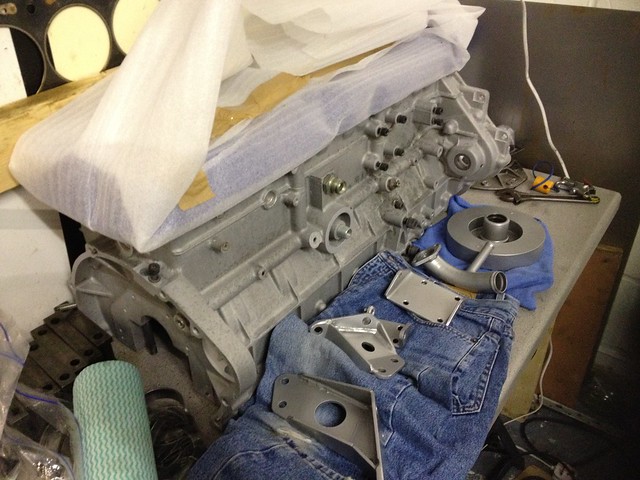
Back to it..
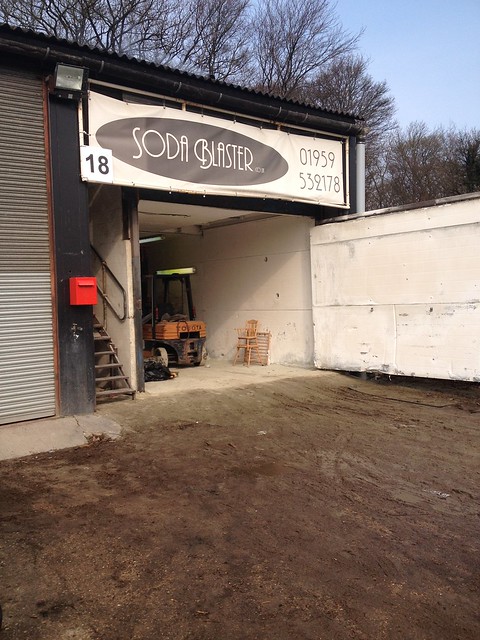
I decided I wanted the engine to look like new when it went back in the car , so literally every single thing was removed from the block so it could be soda blasted before it was relined. The block and all other ancillaries were taken to Soda Blaster in Knockholt.
 IMG_1032 by Barkley Dogue, on Flickr
They did a great job cleaning all of the metal parts I took them including the block, water pipes, engine mount brackets and damper. While they were at it they did me a good deal on powder coating, so I had all of my newly blasted metal parts powder coated. After a week or so I had a call saying everything was ready, so as part of the big team effort, my mum duly went and collected all the parts and dropped them off to me after work one evening. Everything looked great.
I did try power washing the block with Gunk, but it was fairly useless.
 DSC_0156 by Barkley Dogue, on Flickr
Thats better.. parts on bench
 [url=https:
//flic.kr/p/pCM2SD]IMG_1047[/url] by Barkley Dogue, on Flickr
 IMG_1046 by Barkley Dogue, on Flickr
Cam cover prior to polishing..
 IMG_1045 by Barkley Dogue, on Flickr
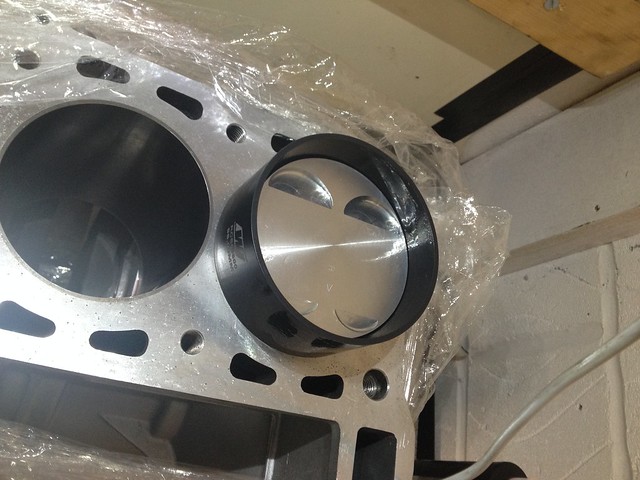
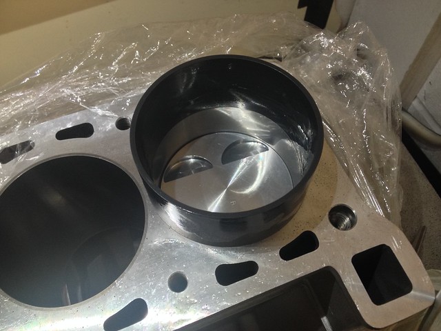
I took several days off the following week in order to get a few more bits done and take the block up to racing green to leave it with them to have it relined.
Disaster!!… upon pressure washing the soda from the block I noticed some black dirt in a line from the corner of the water jackets. I tried scraping the black dirt from the block, but to my horror this wasn’t black dirt.. it was a cracked block!! Son of Jorel, what ever next. There was also a reasonable amount of porosity.
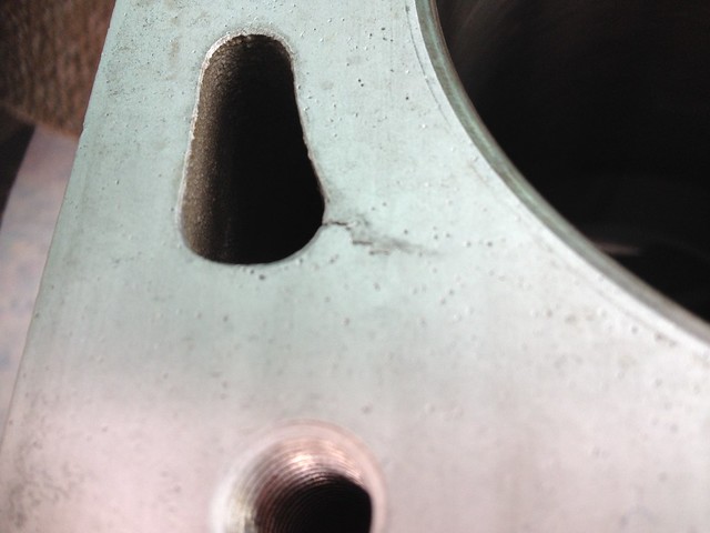 IMG_1049 by Barkley Dogue, on Flickr
Strangely the car never once over heated in my hands. You never know though what your going to get when you open a TVR engine up.
I took the block to Racing green where we reviewed the options. The cracks could be ground out and tig welded back up, but in the end (with my ultimate aim) I decided to take a refurbed block, obviously an unforeseen cost. Mildy stressing.
Racing Green, had the block relined. The engineering partner they use for this does more than simply pressing the liners in, they will heat the block, press the liners, cool the block then measure the height of the liners, then measure once again when the block has been left overnight.
It took a little while for the work on the block and for the head to be completed, so this gave me time for a couple of other important supporting activities.
Engine Work
Whilst the block was being relined I had all of the supporting build components supplied, rods, pistons, clutch cover, light weight flywheel etc. I took all of these components on a visit to Julian Godfrey Engineering to have the bottom end balanced and the crank polished.
Julian Godfrey came with a decent reputation and strong background in motorsport and big power engines builds, most notably the pikes peak Monster Energy RS200!

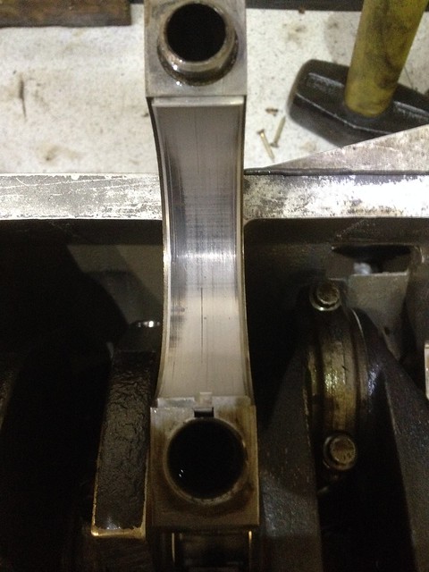
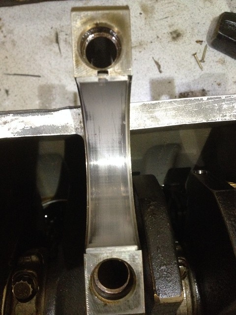
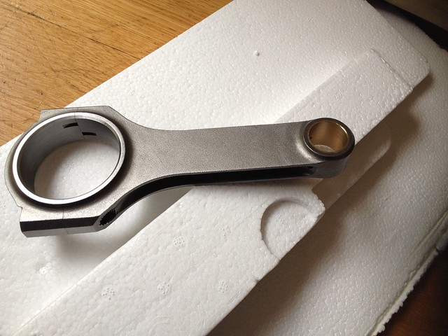
The rods as you can see were a big step up in terms of quality over the standard items, which have had documented failures. The quality of production was also evident in the fact that all of the rods weighed within <1gram of each other. The pistons were also all within 1 gram of each other.
New rods..
 IMG_1072 by Barkley Dogue, on Flickr
Old Rods.... not nice.
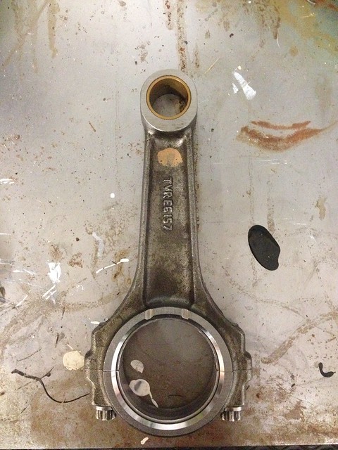 IMG_1506 by Barkley Dogue, on Flickr
Should go nicely with the lighweight flywheel..
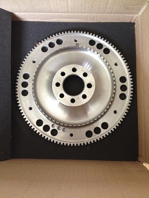 IMG_1071 by Barkley Dogue, on Flickr
The above and all of the other necessary parts were left at Julian Godfrey for several weeks, whilst the balancing and the crank polish was completed. A nice chap called Ray received the parts and went through what I wanted done and gave me a tour of the work shop and the machines used in the process, which was most appreciated.
In addition to the balancing and polishing I got the guys at JG to measure the crank journals and determine whether they were out of round, they came back and said everything was round. This gave some reassurance to the plastigauge readings I had taken as the risk with plastiguage is that the crank is out of round so on the top side of journal you could be in spec but other points could wander out.
On top of all that the price for the work wasn't too outrageous!
Engine bay
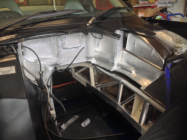
The remainder of the time I had whilst the block work was carried out set about refurbing the engine bay . Both the chassis and the heat shielding material were in a bit of a sorry state. Not awful but could definitely do with a refresh.
 IMG_1125 by Barkley Dogue, on Flickr
 IMG_1123 by Barkley Dogue, on Flickr
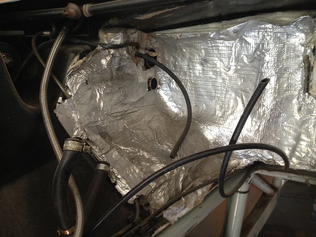
The factory heat shielding was fairly low quality. It predominantly consisted of fibre glass backed baco foil, with complex surfaces heavily taped over to form the shape. It looked fairly rough and delivered that fibreglass itch when touch. In places near the exhaust manifold it had simply disintegrated and was allowing the raw fibre glass to be exposed to the heat.
After ringing round several places I spoke with Nimbus motosport. I spoke to a chap called Chris who was very patient with me, sending out numerous samples of the products they sell, to help me make my decision. Youd think it was easy, but originally I wanted to use gold sheet, but Chris persuaded me otherwise as it would offer no sound proofing from the engine bay and wouldnt be as durable as the shielding I ultimately went for.
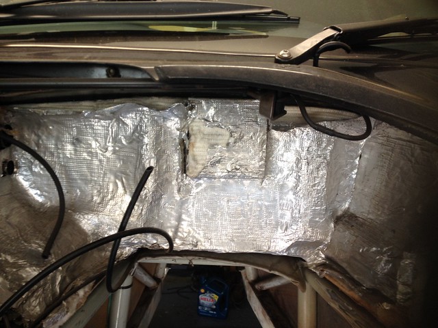
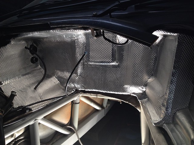
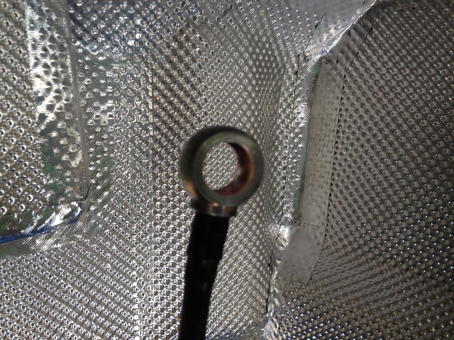
After going through a few samples (All sent out free of charge) a role of DEI floor and tunnel was supplied for the bulkhead and DEI reflect –a-Kool for the chassis and under bonnet areas which were directly exposed to the heat the exhaust manifolds these engines put out ..and they do run typically run hot.
It’s a tedious job, remove the old heat shielding dropping bits of spikey glass fibre, scrubbing the old adhesive off and preparing the bulk head surface, creating templates from the old heat shielding, then cutting out the new panels. I put the new panels in place and secured them with a wall paper roller.
 IMG_1167 by Barkley Dogue, on Flickr
 IMG_1161 by Barkley Dogue, on Flickr
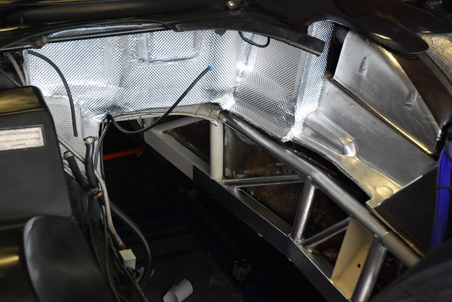 DSC_0160 by Barkley Dogue, on Flickr
I decided I wanted the engine to look like new when it went back in the car , so literally every single thing was removed from the block so it could be soda blasted before it was relined. The block and all other ancillaries were taken to Soda Blaster in Knockholt.
IMG_1032 by Barkley Dogue, on FlickrThey did a great job cleaning all of the metal parts I took them including the block, water pipes, engine mount brackets and damper. While they were at it they did me a good deal on powder coating, so I had all of my newly blasted metal parts powder coated. After a week or so I had a call saying everything was ready, so as part of the big team effort, my mum duly went and collected all the parts and dropped them off to me after work one evening. Everything looked great.
I did try power washing the block with Gunk, but it was fairly useless.
DSC_0156 by Barkley Dogue, on FlickrThats better.. parts on bench
[url=https://flic.kr/p/pCM2SD]IMG_1047[/url] by Barkley Dogue, on Flickr
IMG_1046 by Barkley Dogue, on FlickrCam cover prior to polishing..
IMG_1045 by Barkley Dogue, on FlickrI took several days off the following week in order to get a few more bits done and take the block up to racing green to leave it with them to have it relined.
Disaster!!… upon pressure washing the soda from the block I noticed some black dirt in a line from the corner of the water jackets. I tried scraping the black dirt from the block, but to my horror this wasn’t black dirt.. it was a cracked block!! Son of Jorel, what ever next. There was also a reasonable amount of porosity.
IMG_1049 by Barkley Dogue, on FlickrStrangely the car never once over heated in my hands. You never know though what your going to get when you open a TVR engine up.
I took the block to Racing green where we reviewed the options. The cracks could be ground out and tig welded back up, but in the end (with my ultimate aim) I decided to take a refurbed block, obviously an unforeseen cost. Mildy stressing.
Racing Green, had the block relined. The engineering partner they use for this does more than simply pressing the liners in, they will heat the block, press the liners, cool the block then measure the height of the liners, then measure once again when the block has been left overnight.
It took a little while for the work on the block and for the head to be completed, so this gave me time for a couple of other important supporting activities.
Engine Work
Whilst the block was being relined I had all of the supporting build components supplied, rods, pistons, clutch cover, light weight flywheel etc. I took all of these components on a visit to Julian Godfrey Engineering to have the bottom end balanced and the crank polished.
Julian Godfrey came with a decent reputation and strong background in motorsport and big power engines builds, most notably the pikes peak Monster Energy RS200!
The rods as you can see were a big step up in terms of quality over the standard items, which have had documented failures. The quality of production was also evident in the fact that all of the rods weighed within <1gram of each other. The pistons were also all within 1 gram of each other.
New rods..
IMG_1072 by Barkley Dogue, on FlickrOld Rods.... not nice.
IMG_1506 by Barkley Dogue, on FlickrShould go nicely with the lighweight flywheel..
IMG_1071 by Barkley Dogue, on FlickrThe above and all of the other necessary parts were left at Julian Godfrey for several weeks, whilst the balancing and the crank polish was completed. A nice chap called Ray received the parts and went through what I wanted done and gave me a tour of the work shop and the machines used in the process, which was most appreciated.
In addition to the balancing and polishing I got the guys at JG to measure the crank journals and determine whether they were out of round, they came back and said everything was round. This gave some reassurance to the plastigauge readings I had taken as the risk with plastiguage is that the crank is out of round so on the top side of journal you could be in spec but other points could wander out.
On top of all that the price for the work wasn't too outrageous!
Engine bay
The remainder of the time I had whilst the block work was carried out set about refurbing the engine bay . Both the chassis and the heat shielding material were in a bit of a sorry state. Not awful but could definitely do with a refresh.
IMG_1125 by Barkley Dogue, on FlickrIMG_1123 by Barkley Dogue, on FlickrThe factory heat shielding was fairly low quality. It predominantly consisted of fibre glass backed baco foil, with complex surfaces heavily taped over to form the shape. It looked fairly rough and delivered that fibreglass itch when touch. In places near the exhaust manifold it had simply disintegrated and was allowing the raw fibre glass to be exposed to the heat.
After ringing round several places I spoke with Nimbus motosport. I spoke to a chap called Chris who was very patient with me, sending out numerous samples of the products they sell, to help me make my decision. Youd think it was easy, but originally I wanted to use gold sheet, but Chris persuaded me otherwise as it would offer no sound proofing from the engine bay and wouldnt be as durable as the shielding I ultimately went for.
After going through a few samples (All sent out free of charge) a role of DEI floor and tunnel was supplied for the bulkhead and DEI reflect –a-Kool for the chassis and under bonnet areas which were directly exposed to the heat the exhaust manifolds these engines put out ..and they do run typically run hot.
It’s a tedious job, remove the old heat shielding dropping bits of spikey glass fibre, scrubbing the old adhesive off and preparing the bulk head surface, creating templates from the old heat shielding, then cutting out the new panels. I put the new panels in place and secured them with a wall paper roller.
IMG_1167 by Barkley Dogue, on FlickrIMG_1161 by Barkley Dogue, on FlickrDSC_0160 by Barkley Dogue, on FlickrEdited by m4tti on Monday 13th October 11:50
Hi Rob, the sequence is a bit arse about face, I'll put up what I did with the chassis shortly. The silver on the chassis rail you can see is the Reflect -a-kool heat shield.
Hope the head gasket is going well. Good time to swap your heat shielding
Hope the head gasket is going well. Good time to swap your heat shielding
Edited by m4tti on Sunday 12th October 19:37
Honestly I have no idea. This was supplied as-is by racing green. A number of their parts suppliers are a closely guarded secret. Although I can say the one supplier I know of is ferrari OEM, hence I had confidence in them as the standout parts supplier in the TVR game, so used them exclusively.
Whilst the engine bay was empty I also cleaned the chassis up. I wire brushed any signs of rust and repainted the majority of the area with KBS Rust seal. The chassis areas closest to the Exhaust manifolds got a coating of KBS Extreme heat before receiving the reflective layer. To top the chassis and match the original colour I mixed white and black Hammerite, which was rollered on and looked just as good as the original coating. Things were starting to take on a fresh appearance.
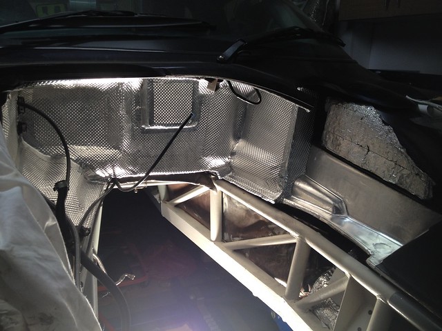
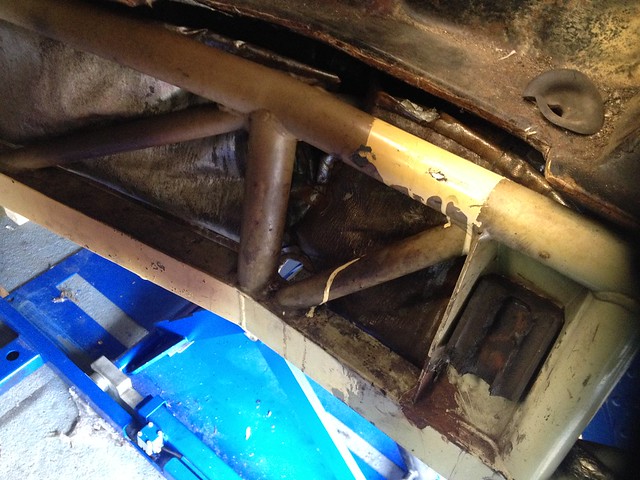
Heat damaged chassis coating next to cats.. It looked a bit grisly where someone had splodged some paint over the cracked chassis coating. You can see where the heat is so severe in that area that the engine mount has crumbled to nothing.
 IMG_1095 by Barkley Dogue, on Flickr
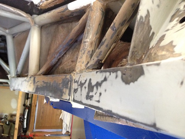
Flaking coating and rust ground back -
 IMG_1127 by Barkley Dogue, on Flickr
A rust removal solution KBS Rust Blast was applied to the area which would etch it with a zinc coating.
High temp paint applied..
 IMG_1150 by Barkley Dogue, on Flickr
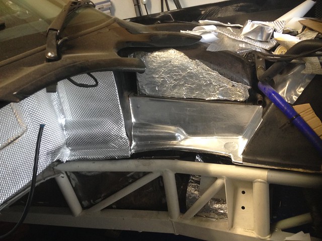
Finally I applied the heat reflective material to the area just to make sure..
 IMG_1179 by Barkley Dogue, on Flickr
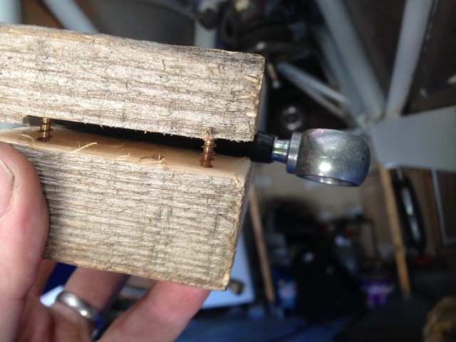
The last thing I had left to do in the engine bay was to re-install the banjo into the rigid fuel line which I foolishly cut off when removing the engine. At the time I removed the engine I couldn’t get the rear banjo bolt to budge and was nervous about damaging the rail and the throttle bodies it mounted on to. I should have persisted and re-fitting that banjo into the rigid nylon fuel line in-situ was a b*tch and. I had make a clamp to support the hose to stop it from kinking. Even when heated the banjo needed some serious oomph to go back in. It would only o back in a couple of mm at a time, otherwise the hose would kink. Each mm, involved heating it in a cup of boiling water and slowly pushing the banjo back in An afternoon spent swearing. Lesson learned, never ever cut that banjo off.
To clamp the hose I took a block of wood and drilled a hole the same diameter as the hose. I then cut the wood in half through the center of the drilled hole.
 IMG_1268 by Barkley Dogue, on Flickr
After many hours it was back in ...
 IMG_1276 by Barkley Dogue, on Flickr
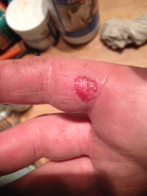
Plus a nice blister for my efforts..
 IMG_1278 by Barkley Dogue, on Flickr
I swear the car hated me!
Heat damaged chassis coating next to cats.. It looked a bit grisly where someone had splodged some paint over the cracked chassis coating. You can see where the heat is so severe in that area that the engine mount has crumbled to nothing.
IMG_1095 by Barkley Dogue, on FlickrFlaking coating and rust ground back -
IMG_1127 by Barkley Dogue, on FlickrA rust removal solution KBS Rust Blast was applied to the area which would etch it with a zinc coating.
High temp paint applied..
IMG_1150 by Barkley Dogue, on FlickrFinally I applied the heat reflective material to the area just to make sure..
IMG_1179 by Barkley Dogue, on FlickrThe last thing I had left to do in the engine bay was to re-install the banjo into the rigid fuel line which I foolishly cut off when removing the engine. At the time I removed the engine I couldn’t get the rear banjo bolt to budge and was nervous about damaging the rail and the throttle bodies it mounted on to. I should have persisted and re-fitting that banjo into the rigid nylon fuel line in-situ was a b*tch and. I had make a clamp to support the hose to stop it from kinking. Even when heated the banjo needed some serious oomph to go back in. It would only o back in a couple of mm at a time, otherwise the hose would kink. Each mm, involved heating it in a cup of boiling water and slowly pushing the banjo back in An afternoon spent swearing. Lesson learned, never ever cut that banjo off.
To clamp the hose I took a block of wood and drilled a hole the same diameter as the hose. I then cut the wood in half through the center of the drilled hole.
IMG_1268 by Barkley Dogue, on FlickrAfter many hours it was back in ...
IMG_1276 by Barkley Dogue, on FlickrPlus a nice blister for my efforts..
IMG_1278 by Barkley Dogue, on FlickrI swear the car hated me!
Engine Build
I had a call letting me know the block and head were ready so I made my way up to RG to collect all the necessary parts. I took everything I needed to put the engine together except for the head. This was assembled by RG and it was agreed with them that I would return the bottom end to them for their engine builder “woody” to put on and time up. An initial install of the crank was performed to ensure my crank and the new block were a good match. Luckily they were and I could run with standard bearings and not need any form of adjustment on the crank or main bearings.
Polished crank journals..
 IMG_1218 - Copy by Barkley Dogue, on Flickr
Assembling the bottom end was fairly straight forward. I wont go in to intricate detail as there are loads of decent books and resources out there to guide you through this. One which I found really useful was actually a US Honda tuning site they had a fairly interesting video http://www.evans-tuning.com/tech-videos/how-to-bui...
Before I did the real assembly I did a dry build to establish the pistons height above deck. I measured this with a dti and relayed the figures to RG, and everything was in order.
I bought a tapered ring compressor to install the pistons. Using the tapered ring compressor made installing the pistons incredibly easy. Obtaining one of these in this size in the UK took some doing.. to my knowledge this was the last one left in this country.
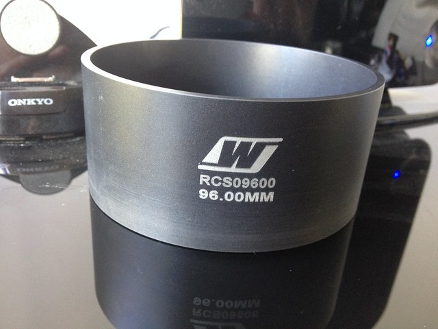 IMG_1171 by Barkley Dogue, on Flickr
Put piston on rod, put rings on piston, verify ring gaps on piston, align rings, line up ring compressor and simply push in. The pistons could be installed in this way with just finger pressure. I lubricated all gudgeon pins with Toroco engine build lube and coated the cylinders with standard mineral oil.
Pistons, rods, and gudgeon pins ready for assembly..
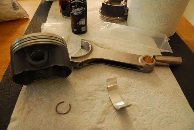 DSC_0180 by Barkley Dogue, on Flickr
Piston and rod dropped in through tapered ring compressor..
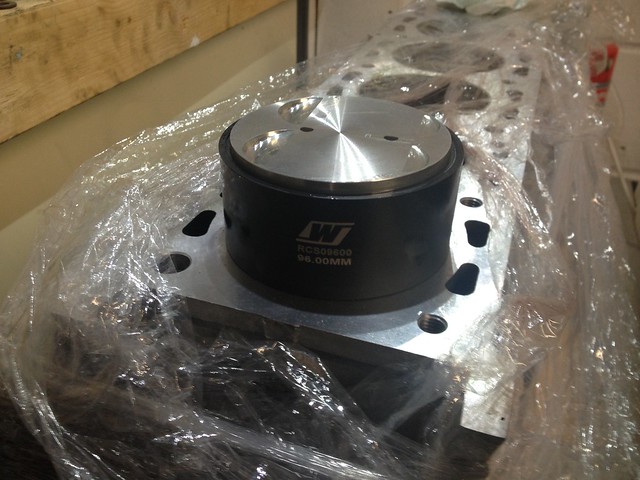 IMG_1247 by Barkley Dogue, on Flickr
Gentle pressure and it starts to locate into the bore...
 IMG_1248 by Barkley Dogue, on Flickr
And its in..
 IMG_1249 by Barkley Dogue, on Flickr
Taking no chances with dirt, I kept the bottom end heavily wrapped only unwrapping areas I needed access to when required.
Con rod installations was completed using Arp bolts. I’d never assembled the bottom end of an engine before so was fairly nervous considering the total cost of the parts involved, but I think if I had to do it again I’d feel more comfortable. The main thing is to take your time, and double check, and triple check everything, and at all stages make sure the engine feels right. Nothing should be binding. I marked everything as I went indicating it had been torque up as necessary.
The water pump and high pressure oil pump were rebuilt by RG as some tooling which I didn’t have was required, I could probably have fabricated these my self, but I really wanted to get the car back on the road before the end of summer. I did rebuild the scavenge pump which returns oil from the sump to the dry sump tank.
Scavenge pump..lots of bits..
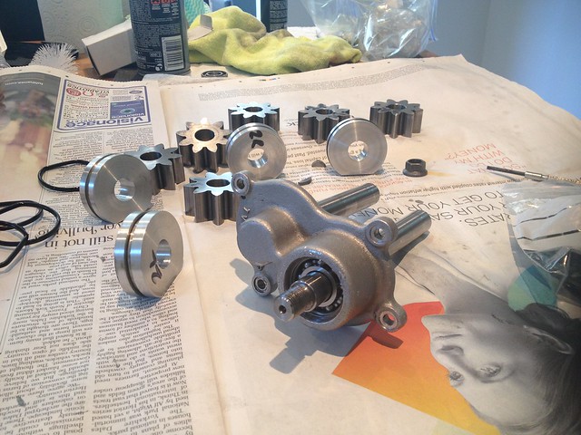 IMG_1250 by Barkley Dogue, on Flickr
And back together again.. bearings replaced and all O-rings renewed
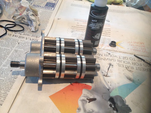 IMG_1251 by Barkley Dogue, on Flickr
Again no rocket science here but it needs a patient logical approach, and thorough inspection of parts.
Although I completely understood the principal of timing the engine up with a degree wheel there were zero reference points to use. You essentially use a Degree wheel on the crank to find TDC, and a DTI on number 1 cam to determine the centre line angle. I took the decision in the end to have the head put on and timed up by RG, I had timed up the old engine, but felt more comfortable having it done by someone familiar with the FFF considering its cost and the fact I had to collect it as it required assembly. I couldn't even compare to the reference marks I made on my old head as the timing pf the new head would be somewhat different.
First glimpse of head waiting for assembly..
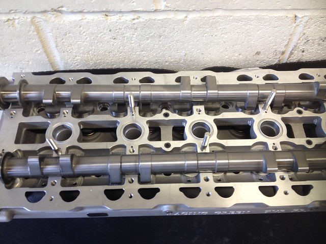 IMG_1227 by Barkley Dogue, on Flickr
 IMG_1223 by Barkley Dogue, on Flickr
It was almost too nice to use
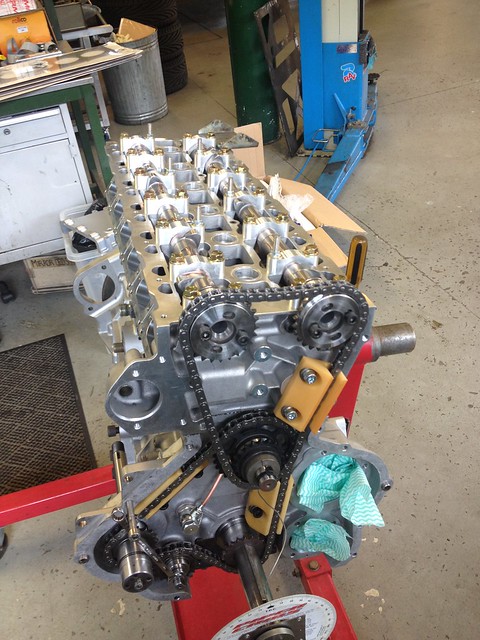
Whilst the head was installed the existing duplex timing gear was replaced with RG’s simplex timing set up. The standard half time shaft of this engine was originally supported by a splash fed bearing, this was replaced by a pressure fed roller bearing. As well as the improved oiling to the bearing the simplex setup dropped a considerable weight from the timing set up, in the region of a kilo. On top of that specification of the simplex chain was more than good enough to offer the same load carrying capabilities to remove the duplex setup. In the January when I was researching components, I ended up in the RG parts warehouse along with Colin their MD, where we weighed the standard timing setup and the simplex on their mail room scales. I was suitably impressed.
Phwooooarrrr
 IMG_1258 by Barkley Dogue, on Flickr
The standard head bolts were replaced with studs.
The simplex set up and the lightweight flywheel should ultimately help the engine spin up quicker!
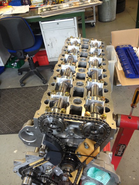
In the RG workshop the head was put on by their engine builder “woody” (Steve Woodrow), I was lucky enough to get the chance to observe. Woody is another top guy who I’ve met along this journey, he was extremely patient and endured all of my questions. It was a really good learning experience and he gave me some top tips, which I wouldn’t have thought of, again giving me more confidence should the need arise in the future. Thanks again Woody!
A few shots of the engine going back together
 IMG_1261 by Barkley Dogue, on Flickr
 IMG_1264 by Barkley Dogue, on Flickr
 IMG_1254 by Barkley Dogue, on Flickr
I had a call letting me know the block and head were ready so I made my way up to RG to collect all the necessary parts. I took everything I needed to put the engine together except for the head. This was assembled by RG and it was agreed with them that I would return the bottom end to them for their engine builder “woody” to put on and time up. An initial install of the crank was performed to ensure my crank and the new block were a good match. Luckily they were and I could run with standard bearings and not need any form of adjustment on the crank or main bearings.
Polished crank journals..
IMG_1218 - Copy by Barkley Dogue, on FlickrAssembling the bottom end was fairly straight forward. I wont go in to intricate detail as there are loads of decent books and resources out there to guide you through this. One which I found really useful was actually a US Honda tuning site they had a fairly interesting video http://www.evans-tuning.com/tech-videos/how-to-bui...
Before I did the real assembly I did a dry build to establish the pistons height above deck. I measured this with a dti and relayed the figures to RG, and everything was in order.
I bought a tapered ring compressor to install the pistons. Using the tapered ring compressor made installing the pistons incredibly easy. Obtaining one of these in this size in the UK took some doing.. to my knowledge this was the last one left in this country.
IMG_1171 by Barkley Dogue, on FlickrPut piston on rod, put rings on piston, verify ring gaps on piston, align rings, line up ring compressor and simply push in. The pistons could be installed in this way with just finger pressure. I lubricated all gudgeon pins with Toroco engine build lube and coated the cylinders with standard mineral oil.
Pistons, rods, and gudgeon pins ready for assembly..
DSC_0180 by Barkley Dogue, on FlickrPiston and rod dropped in through tapered ring compressor..
IMG_1247 by Barkley Dogue, on FlickrGentle pressure and it starts to locate into the bore...
IMG_1248 by Barkley Dogue, on FlickrAnd its in..
IMG_1249 by Barkley Dogue, on FlickrTaking no chances with dirt, I kept the bottom end heavily wrapped only unwrapping areas I needed access to when required.
Con rod installations was completed using Arp bolts. I’d never assembled the bottom end of an engine before so was fairly nervous considering the total cost of the parts involved, but I think if I had to do it again I’d feel more comfortable. The main thing is to take your time, and double check, and triple check everything, and at all stages make sure the engine feels right. Nothing should be binding. I marked everything as I went indicating it had been torque up as necessary.
The water pump and high pressure oil pump were rebuilt by RG as some tooling which I didn’t have was required, I could probably have fabricated these my self, but I really wanted to get the car back on the road before the end of summer. I did rebuild the scavenge pump which returns oil from the sump to the dry sump tank.
Scavenge pump..lots of bits..
IMG_1250 by Barkley Dogue, on FlickrAnd back together again.. bearings replaced and all O-rings renewed
IMG_1251 by Barkley Dogue, on FlickrAgain no rocket science here but it needs a patient logical approach, and thorough inspection of parts.
Although I completely understood the principal of timing the engine up with a degree wheel there were zero reference points to use. You essentially use a Degree wheel on the crank to find TDC, and a DTI on number 1 cam to determine the centre line angle. I took the decision in the end to have the head put on and timed up by RG, I had timed up the old engine, but felt more comfortable having it done by someone familiar with the FFF considering its cost and the fact I had to collect it as it required assembly. I couldn't even compare to the reference marks I made on my old head as the timing pf the new head would be somewhat different.
First glimpse of head waiting for assembly..
IMG_1227 by Barkley Dogue, on FlickrIMG_1223 by Barkley Dogue, on FlickrIt was almost too nice to use
Whilst the head was installed the existing duplex timing gear was replaced with RG’s simplex timing set up. The standard half time shaft of this engine was originally supported by a splash fed bearing, this was replaced by a pressure fed roller bearing. As well as the improved oiling to the bearing the simplex setup dropped a considerable weight from the timing set up, in the region of a kilo. On top of that specification of the simplex chain was more than good enough to offer the same load carrying capabilities to remove the duplex setup. In the January when I was researching components, I ended up in the RG parts warehouse along with Colin their MD, where we weighed the standard timing setup and the simplex on their mail room scales. I was suitably impressed.
Phwooooarrrr
IMG_1258 by Barkley Dogue, on FlickrThe standard head bolts were replaced with studs.
The simplex set up and the lightweight flywheel should ultimately help the engine spin up quicker!
In the RG workshop the head was put on by their engine builder “woody” (Steve Woodrow), I was lucky enough to get the chance to observe. Woody is another top guy who I’ve met along this journey, he was extremely patient and endured all of my questions. It was a really good learning experience and he gave me some top tips, which I wouldn’t have thought of, again giving me more confidence should the need arise in the future. Thanks again Woody!
A few shots of the engine going back together
IMG_1261 by Barkley Dogue, on FlickrIMG_1264 by Barkley Dogue, on FlickrIMG_1254 by Barkley Dogue, on FlickrEdited by m4tti on Wednesday 15th October 23:08
Edited by m4tti on Wednesday 15th October 23:09
Edited by m4tti on Saturday 18th October 20:04
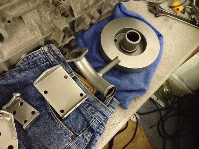
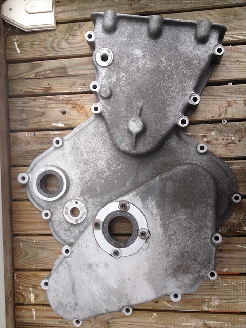
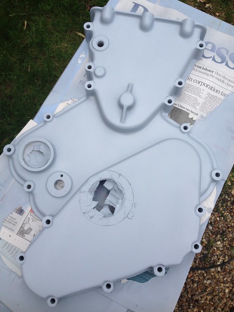
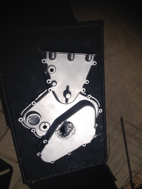
Missed this from the last instalment.. The engine was finished off nicely with a refurbed timing cover. It had been soda blasted but sat around long enough to get furry again. The alloy came up ok with some wonder wheels, acid etch and engine paint.
 IMG_1202 - Copy by Barkley Dogue, on Flickr
Cleaned up..
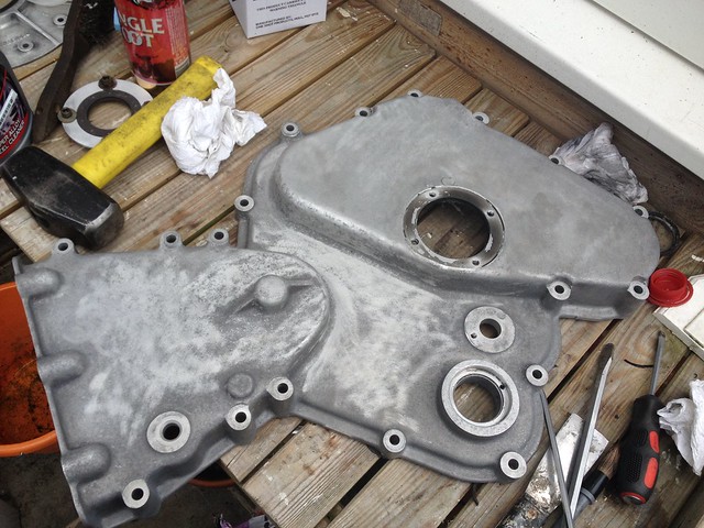 IMG_1203 - Copy by Barkley Dogue, on Flickr
Acid Etch..
 IMG_1204 - Copy by Barkley Dogue, on Flickr
Finished..
 IMG_1234 by Barkley Dogue, on Flickr
Putting it all back…
We unloaded the engine from the landrover and put it back on the home made skid ready to be positioned in its old home.
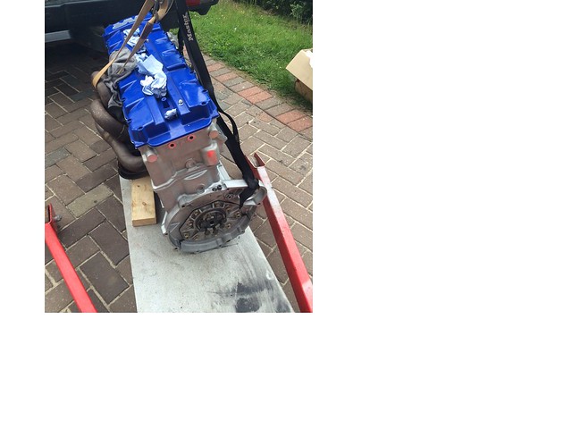 NewEngine2 by Barkley Dogue, on Flickr
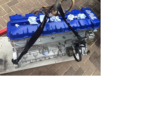 NewEngine3 by Barkley Dogue, on Flickr
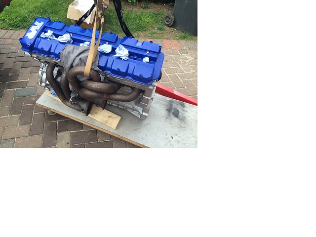 NewEngine1 by Barkley Dogue, on Flickr
Putting all of this lot back was just about a frustrating as taking it out. Certain parts (again) had a very distinct order of operations.
The engine on the skid was pushed back under the raised chassis. It was fairly straight forward getting the engine physically in the engine bay, but it was a two man job to cant it back over the necessary degrees and bolt the engine mounts in place.
Slowly but surely things were starting to take shape.
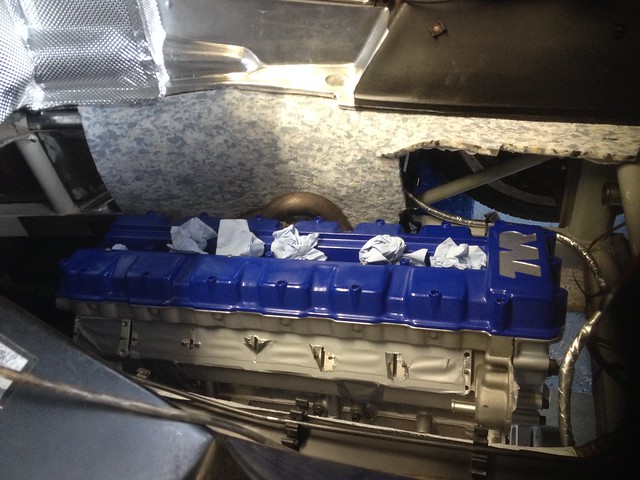 IMG_1287 by Barkley Dogue, on Flickr
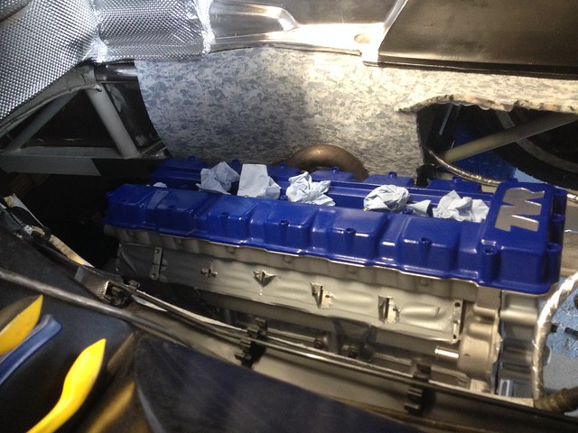 IMG_1286 by Barkley Dogue, on Flickr
 IMG_1288 by Barkley Dogue, on Flickr
I had bought a set of refurbed roller bearing-ed throttle bodies the year previous. Instead of a floating shaft with a felt washed behind a nut locking the shaft in place, these used sealed roller bearings. They certainly looked the part, but things weren’t quite as good as they seemed.. we’ll come back to that
New body with roller bearing
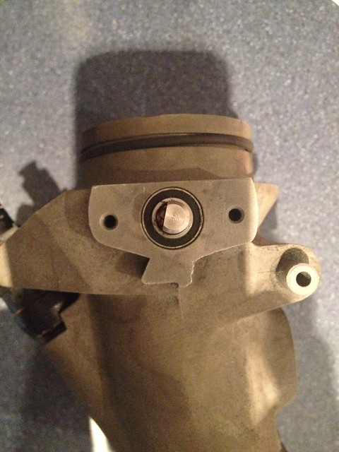 IMG_1302 by Barkley Dogue, on Flickr
Old body with felt bush
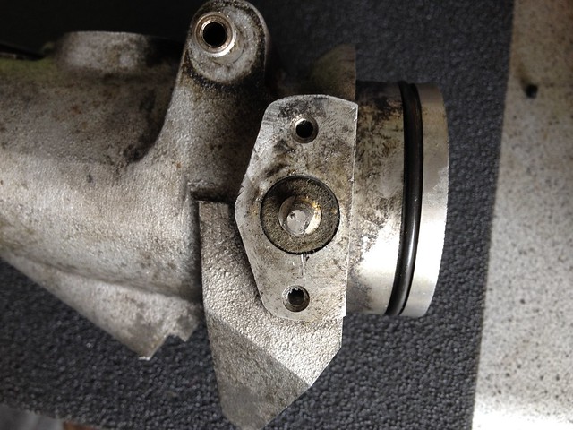 IMG_1301 by Barkley Dogue, on Flickr
The throttle bodies were mounted on the head with a set of bespoke gaskets. The gaskets were provided by Andy_MR2Sc who advertises on PH. Another good guy I’ve met on this journey who is a top machinist and has some great ideas for improved parts. Typically the throttle bodies are sealed in place using hylomar…. These I felt were a good improvement on the standard process, certainly in terms of ease of fitment.
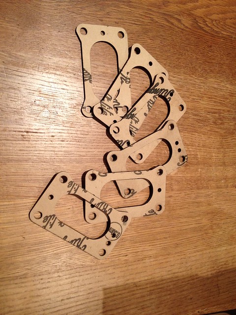 IMG_1294 by Barkley Dogue, on Flickr
Before the oil system could be connected back up, it needed to be flushed so the dry sump tank was removed and paraffin was left in it for several days. I then flushed it with a hose to ensure everything ran clear and gave it one last flush with paraffin. I decided to replace the oil lines as they were looking tired around the fitting.
Again this was all fairly simple stuff but laborious.
Minor issues cropped up all the way, such as the stud on the power steering bracket that locates the power steering tensioner had somehow been snapped off… annoyingly I hadn’t noticed before it was powder coated. Luckily I had a spare block at my mums with one of these still on it, otherwise it would have a been a bit of hunt for one.
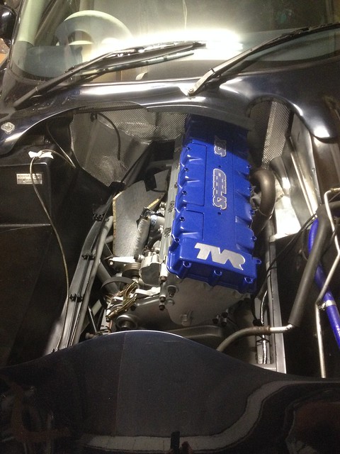
Piece by piece it all went back..
 IMG_1317 by Barkley Dogue, on Flickr
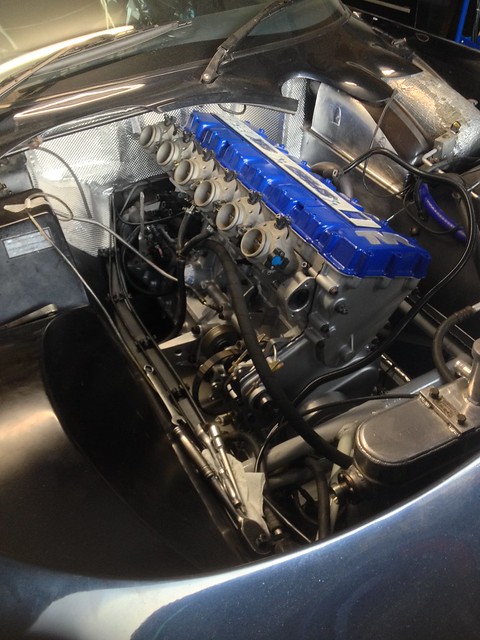
Eventually it was all back and the day of the first fire came along!
First fire, just lucky it wasn’t a real fire!
After priming the oil system and letting the car turn over on the starter, and seeing strong oil pressure I went for the first fire up.
To my amazement the thing fired on the first start of the key. I quickly got the revs up for the initial cam break in. I was prepared, I had my mum holding a fire extinguisher and my wife and little brother checking for leaks. I held the revs up at about 2k, at which the noise is fairly deafening .. You couldn’t hear much. Mum shouted over to me that there was liquid at the back of the car….
“Liquid” I thought, so shouted back, “what liquid”. She checked it out and shouted back petrol… woah! I quickly shut it down. I checked the banjo I’d replaced and it was dry as a bone. Where was this coming from?? There were no leaks when I put it in the garage and started the strip down.
A lot of petrol
 IMG_1336 by Barkley Dogue, on Flickr
The car was wheeled back into the garage, I felt a bit deflated, so near but so far. What had happened? How could this be!
I got the car back on the ramp and that weekend set about trying to diagnose the issue. There was so much fuel it must have been the fuel feed.. Every time I primed the fuel pump fuel would pish down from above. After messing about taking the rusty banjo off the fuel filter and blowing in it there was no leak on that side (what a waste of time). I then took the return off the fuel rail and blew down that.. to my amazement I could hear air escaping under the car. As I cast my mind back it dawned on me, what had happened.
When the car was up on the ramp and I was doing some of the engine bay re-furb I went to roll the car off the ramp a few feet. I didn’t realise at the time the return line was trapped under one of the ramps skid plates..un-beknown to me when I went to roll the car forward, with the trapped return line, it was simply dragging the pipe out of place. I noticed it at the time but was more concerned about it being crushed by the weight of the ramp platform. On the crushing front it was fine... Son of beech.
In the end I replaced the return line, it had gone too stiff to relocate without kinking. Thinking that was the end of it I rolled the car back out for a test fire and unbelievable there were more leaks.. this time the fittings on the fuel filter which were disturbed. I discovered this on Thursday night but wanted to get the car going at the weekend, so I took a trip down to Pirtek Medway who sorted out a new filter to pump hose for me. I primed the system again and luckily that was the end of the leaks. Two weeks of weekends wasted…
After a morning of putting it all back together the moment came when I could fire her up. Again she started on the button, Great I thought. I ran the car back up to temperature and began to feel a sense of relief. Once up to temperature I started balancing the throttle bodies.
After many attempts I simply couldn’t get the hot idle below about 1200 rpm. Was it the new head drawing so much air.. of course not! I relayed the info to RG and they too had never heard this, but instantly asked whether I was using my original throttle bodies. Obviously I wasn’t.
I tried all sorts of things. I looked at the balance springs between the butterflies and thought they might be worn and not providing enough return force, so replaced these.. Nope wasn’t this.
I loosened the butterflies and tickled them about to try and make them more central in case they were put out by the refurb, but still no joy. The idle was high and I just didn’t want to drive the car until it was running perfect. In the end the new bodies had to come off and were put on the bench to do some comparison tests.
Once on the bench I compared the bodies to the old bodies. A simple test of sealing a new closed throttle body over my mouth and blowing, and repeating the same test with the old body revealed the new bodies simply leaked a lot of air. It would appear that the interior of the body mouth was blasted. It perhaps only removed a thou or two of material and possibly left a microscopic dimpled surface, but it left them leaking air horribly. They were essentially junk, and were supposed to enhance that completely new feel of the set up. Annoying!! Not a lot I could do after having had them sat there for over a year waiting.
The moral of this story is to tread carefully with specialist parts. Don’t take anything for granted… it made me think how I could have validated the part before leaving the cash behind..
After discovering that the new bodies were effectively useless I set about stripping off the throttle bodies and mounting the old throttle bodies and putting everything back together.
After wrestling the fuel rail back on, I pressurised the system. No leaks!
This time I fired her up, balanced the throttle bodies and was able to get a hot idle of 900 rpm. Halleluiah!
So that was it… oh no it wasn’t. Upon my first real test drive doing one of my favourite loops round the local country side I pulled into a petrol station and discovered that with the high under bonnet temps the car wouldn’t restart. So now theres a hot start problem. Turn the key and the voltage would plummet and the starter just didn’t want to even click. I waited 20 mins and got it going again.
The following weekend I set about cleaning all the earth points. Of course this is easier said than done on these things.. wheel off, battery out, under tray off etc etc After a couple of hours and a load of di-electric grease everything was sorted and I was back on the road again.
Whats it like…
Although im still getting used to the car and its still in its running in phase the engine is awesome. Cold oil pressure at start up is now in the 90 psi range… and hot idle oil pressure is now in the the 30 psi range, not the 9 – 12 psi range.. yes you heard right that’s right 9psi. Which is simply bonkers. Gone is the sewing machine sound, this has been replaced by a methodical rythm of the cams and turbine sound of the simplex chain system.. No more clattering chains. Can you tell im pleased so far… Its worlds apart from the original engine, but it has in fact enhanced its character.
I’ve done about 600 miles, and haven’t really taken it above 4750 rpm .. but even at that level it really starts coming on song.. there’s no gear where 4750 rpm is legal.
The finished engine bay
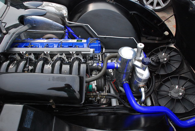 DSC_0193 by Barkley Dogue, on Flickr
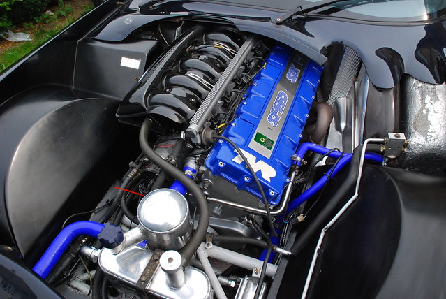 DSC_0188 by Barkley Dogue, on Flickr
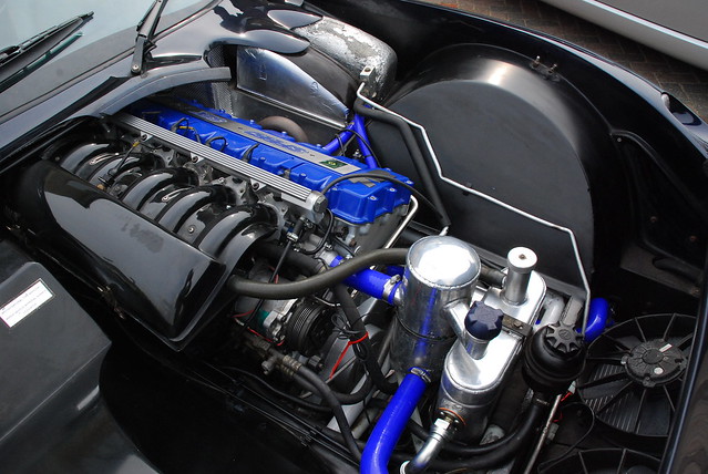 DSC_0192 by Barkley Dogue, on Flickr
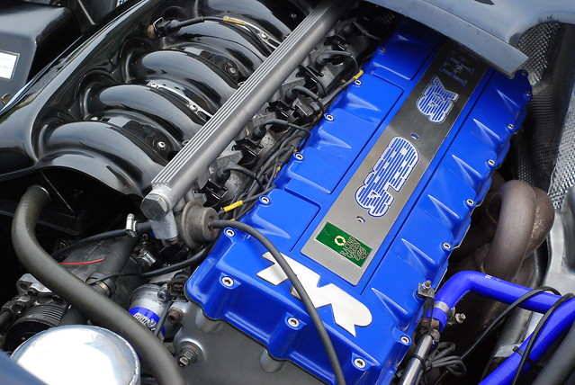 DSC_0185 by Barkley Dogue, on Flickr
Ahh but that’s not all!
Well with all the knock backs I had with the mechanical stuff I had to do a bit of retail therapy and do some cosmetic stuff. Carbon Fibre Seat backs…. Well not just cosmetic. The original seat backs crack, and believe it or not they do actually serve a purpose. They prevent your back from becoming concave and being squirted out the back of the seat frame. Trust me this isn’t pleasant for any longer than an hour, you can develop a high quality bad back from this posture very rapidly.
These came from Carbon Delight. It took Phil (owner of Carbon Delight) a little while to do them as the first pair he did were moulded from leather backed seat backs and weren’t the right shape, but he had no problem in taking them back, taking one of my original backs and creating a new former.
Again Phil is another top man, he took me through the process of the making carbon fibre parts in his workshop. He came across as passionate about creating quality parts and above all even though the original backs were wrong he came through with replacements. The finish is awesome! What more can you want! Unsung heroes of Britains niche industries, lets make sure we keep them alive.
 IMG_0506 by Barkley Dogue, on Flickr
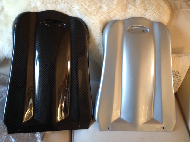 IMG_1323 by Barkley Dogue, on Flickr
What Next..
Ive got a list of things (copied below) I’d like to do, but now the big bits done so is the challenge... I’ve lately been thinking of maybe getting hold of a Noble that could do with some TLC.. or the wife would like a break from these sort of cars
Stuff to do..
Syvecs stand alone management
Larger injectors
Large bore exhaust- Most fit the act large bore exhaust system for increased power, but I think more time could be spent on this looking for a better sound and flow!
Bespoke map
Configure traction control
Refurb steering wheel
Replace Carpets
Refurb wheels.. in black!
Respray in original colour, but perhaps with a stronger metallic!
Thanks to…
Just like to say thanks for all the help the following people have provided.
Mainly my wife for enduring the swearing and the tantrums, Colin at RG for listening to many questions many times some even repeated, my little brother for helping and enduring the tempers and swearing.
My best mate mark for helping me getting the engine out and back in, and helping me reduce the EU beer mountain. We drank a few whilst contemplating tactics..
AndyMr2sc who I met via piston heads, who helped me solve my throttle body issues and have since have had a couple of good afternoons out,
John (Sagi_badger) for answering a whole bunch of texts, whilst he was going though his own rebuild.
And lastly my mum for listening to weekly whingeing and holding the fire extinguisher! That’s what mums are for.
There's bound to be others I've forgotten as I sit here.... So Alan, rich and and any one else who spared some hours on the way. Thanks again.
Thanks for listening.
Good luck in your own projects!
Children let this TVR tale be a warning to you :P
IMG_1202 - Copy by Barkley Dogue, on FlickrCleaned up..
IMG_1203 - Copy by Barkley Dogue, on FlickrAcid Etch..
IMG_1204 - Copy by Barkley Dogue, on FlickrFinished..
IMG_1234 by Barkley Dogue, on FlickrPutting it all back…
We unloaded the engine from the landrover and put it back on the home made skid ready to be positioned in its old home.
NewEngine2 by Barkley Dogue, on FlickrNewEngine3 by Barkley Dogue, on FlickrNewEngine1 by Barkley Dogue, on FlickrPutting all of this lot back was just about a frustrating as taking it out. Certain parts (again) had a very distinct order of operations.
The engine on the skid was pushed back under the raised chassis. It was fairly straight forward getting the engine physically in the engine bay, but it was a two man job to cant it back over the necessary degrees and bolt the engine mounts in place.
Slowly but surely things were starting to take shape.
IMG_1287 by Barkley Dogue, on FlickrIMG_1286 by Barkley Dogue, on FlickrIMG_1288 by Barkley Dogue, on FlickrI had bought a set of refurbed roller bearing-ed throttle bodies the year previous. Instead of a floating shaft with a felt washed behind a nut locking the shaft in place, these used sealed roller bearings. They certainly looked the part, but things weren’t quite as good as they seemed.. we’ll come back to that
New body with roller bearing
IMG_1302 by Barkley Dogue, on FlickrOld body with felt bush
IMG_1301 by Barkley Dogue, on FlickrThe throttle bodies were mounted on the head with a set of bespoke gaskets. The gaskets were provided by Andy_MR2Sc who advertises on PH. Another good guy I’ve met on this journey who is a top machinist and has some great ideas for improved parts. Typically the throttle bodies are sealed in place using hylomar…. These I felt were a good improvement on the standard process, certainly in terms of ease of fitment.
IMG_1294 by Barkley Dogue, on FlickrBefore the oil system could be connected back up, it needed to be flushed so the dry sump tank was removed and paraffin was left in it for several days. I then flushed it with a hose to ensure everything ran clear and gave it one last flush with paraffin. I decided to replace the oil lines as they were looking tired around the fitting.
Again this was all fairly simple stuff but laborious.
Minor issues cropped up all the way, such as the stud on the power steering bracket that locates the power steering tensioner had somehow been snapped off… annoyingly I hadn’t noticed before it was powder coated. Luckily I had a spare block at my mums with one of these still on it, otherwise it would have a been a bit of hunt for one.
Piece by piece it all went back..
IMG_1317 by Barkley Dogue, on FlickrEventually it was all back and the day of the first fire came along!
First fire, just lucky it wasn’t a real fire!
After priming the oil system and letting the car turn over on the starter, and seeing strong oil pressure I went for the first fire up.
To my amazement the thing fired on the first start of the key. I quickly got the revs up for the initial cam break in. I was prepared, I had my mum holding a fire extinguisher and my wife and little brother checking for leaks. I held the revs up at about 2k, at which the noise is fairly deafening .. You couldn’t hear much. Mum shouted over to me that there was liquid at the back of the car….
“Liquid” I thought, so shouted back, “what liquid”. She checked it out and shouted back petrol… woah! I quickly shut it down. I checked the banjo I’d replaced and it was dry as a bone. Where was this coming from?? There were no leaks when I put it in the garage and started the strip down.
A lot of petrol
IMG_1336 by Barkley Dogue, on FlickrThe car was wheeled back into the garage, I felt a bit deflated, so near but so far. What had happened? How could this be!
I got the car back on the ramp and that weekend set about trying to diagnose the issue. There was so much fuel it must have been the fuel feed.. Every time I primed the fuel pump fuel would pish down from above. After messing about taking the rusty banjo off the fuel filter and blowing in it there was no leak on that side (what a waste of time). I then took the return off the fuel rail and blew down that.. to my amazement I could hear air escaping under the car. As I cast my mind back it dawned on me, what had happened.
When the car was up on the ramp and I was doing some of the engine bay re-furb I went to roll the car off the ramp a few feet. I didn’t realise at the time the return line was trapped under one of the ramps skid plates..un-beknown to me when I went to roll the car forward, with the trapped return line, it was simply dragging the pipe out of place. I noticed it at the time but was more concerned about it being crushed by the weight of the ramp platform. On the crushing front it was fine... Son of beech.
In the end I replaced the return line, it had gone too stiff to relocate without kinking. Thinking that was the end of it I rolled the car back out for a test fire and unbelievable there were more leaks.. this time the fittings on the fuel filter which were disturbed. I discovered this on Thursday night but wanted to get the car going at the weekend, so I took a trip down to Pirtek Medway who sorted out a new filter to pump hose for me. I primed the system again and luckily that was the end of the leaks. Two weeks of weekends wasted…
After a morning of putting it all back together the moment came when I could fire her up. Again she started on the button, Great I thought. I ran the car back up to temperature and began to feel a sense of relief. Once up to temperature I started balancing the throttle bodies.
After many attempts I simply couldn’t get the hot idle below about 1200 rpm. Was it the new head drawing so much air.. of course not! I relayed the info to RG and they too had never heard this, but instantly asked whether I was using my original throttle bodies. Obviously I wasn’t.
I tried all sorts of things. I looked at the balance springs between the butterflies and thought they might be worn and not providing enough return force, so replaced these.. Nope wasn’t this.
I loosened the butterflies and tickled them about to try and make them more central in case they were put out by the refurb, but still no joy. The idle was high and I just didn’t want to drive the car until it was running perfect. In the end the new bodies had to come off and were put on the bench to do some comparison tests.
Once on the bench I compared the bodies to the old bodies. A simple test of sealing a new closed throttle body over my mouth and blowing, and repeating the same test with the old body revealed the new bodies simply leaked a lot of air. It would appear that the interior of the body mouth was blasted. It perhaps only removed a thou or two of material and possibly left a microscopic dimpled surface, but it left them leaking air horribly. They were essentially junk, and were supposed to enhance that completely new feel of the set up. Annoying!! Not a lot I could do after having had them sat there for over a year waiting.
The moral of this story is to tread carefully with specialist parts. Don’t take anything for granted… it made me think how I could have validated the part before leaving the cash behind..
After discovering that the new bodies were effectively useless I set about stripping off the throttle bodies and mounting the old throttle bodies and putting everything back together.
After wrestling the fuel rail back on, I pressurised the system. No leaks!
This time I fired her up, balanced the throttle bodies and was able to get a hot idle of 900 rpm. Halleluiah!
So that was it… oh no it wasn’t. Upon my first real test drive doing one of my favourite loops round the local country side I pulled into a petrol station and discovered that with the high under bonnet temps the car wouldn’t restart. So now theres a hot start problem. Turn the key and the voltage would plummet and the starter just didn’t want to even click. I waited 20 mins and got it going again.
The following weekend I set about cleaning all the earth points. Of course this is easier said than done on these things.. wheel off, battery out, under tray off etc etc After a couple of hours and a load of di-electric grease everything was sorted and I was back on the road again.
Whats it like…
Although im still getting used to the car and its still in its running in phase the engine is awesome. Cold oil pressure at start up is now in the 90 psi range… and hot idle oil pressure is now in the the 30 psi range, not the 9 – 12 psi range.. yes you heard right that’s right 9psi. Which is simply bonkers. Gone is the sewing machine sound, this has been replaced by a methodical rythm of the cams and turbine sound of the simplex chain system.. No more clattering chains. Can you tell im pleased so far… Its worlds apart from the original engine, but it has in fact enhanced its character.
I’ve done about 600 miles, and haven’t really taken it above 4750 rpm .. but even at that level it really starts coming on song.. there’s no gear where 4750 rpm is legal.
The finished engine bay
DSC_0193 by Barkley Dogue, on FlickrDSC_0188 by Barkley Dogue, on FlickrDSC_0192 by Barkley Dogue, on FlickrDSC_0185 by Barkley Dogue, on FlickrAhh but that’s not all!
Well with all the knock backs I had with the mechanical stuff I had to do a bit of retail therapy and do some cosmetic stuff. Carbon Fibre Seat backs…. Well not just cosmetic. The original seat backs crack, and believe it or not they do actually serve a purpose. They prevent your back from becoming concave and being squirted out the back of the seat frame. Trust me this isn’t pleasant for any longer than an hour, you can develop a high quality bad back from this posture very rapidly.
These came from Carbon Delight. It took Phil (owner of Carbon Delight) a little while to do them as the first pair he did were moulded from leather backed seat backs and weren’t the right shape, but he had no problem in taking them back, taking one of my original backs and creating a new former.
Again Phil is another top man, he took me through the process of the making carbon fibre parts in his workshop. He came across as passionate about creating quality parts and above all even though the original backs were wrong he came through with replacements. The finish is awesome! What more can you want! Unsung heroes of Britains niche industries, lets make sure we keep them alive.
IMG_0506 by Barkley Dogue, on FlickrIMG_1323 by Barkley Dogue, on FlickrWhat Next..
Ive got a list of things (copied below) I’d like to do, but now the big bits done so is the challenge... I’ve lately been thinking of maybe getting hold of a Noble that could do with some TLC.. or the wife would like a break from these sort of cars
Stuff to do..
Syvecs stand alone management
Larger injectors
Large bore exhaust- Most fit the act large bore exhaust system for increased power, but I think more time could be spent on this looking for a better sound and flow!
Bespoke map
Configure traction control
Refurb steering wheel
Replace Carpets
Refurb wheels.. in black!
Respray in original colour, but perhaps with a stronger metallic!
Thanks to…
Just like to say thanks for all the help the following people have provided.
Mainly my wife for enduring the swearing and the tantrums, Colin at RG for listening to many questions many times some even repeated, my little brother for helping and enduring the tempers and swearing.
My best mate mark for helping me getting the engine out and back in, and helping me reduce the EU beer mountain. We drank a few whilst contemplating tactics..
AndyMr2sc who I met via piston heads, who helped me solve my throttle body issues and have since have had a couple of good afternoons out,
John (Sagi_badger) for answering a whole bunch of texts, whilst he was going though his own rebuild.
And lastly my mum for listening to weekly whingeing and holding the fire extinguisher! That’s what mums are for.
There's bound to be others I've forgotten as I sit here.... So Alan, rich and and any one else who spared some hours on the way. Thanks again.
Thanks for listening.
Good luck in your own projects!
Children let this TVR tale be a warning to you :P
Edited by m4tti on Monday 20th October 21:55
Edited by m4tti on Monday 20th October 22:43
Edited by m4tti on Saturday 25th October 10:31
Edited by m4tti on Sunday 26th October 21:58
Sagi Badger said:
Hi Matt,
Sweet looking build. I've heard enough about it by text.... first real pics I've seen. I missed this thread, just been so busy. Can I ask what you gapped your rings to, I have skim read this as I am supposed to be something else right now so excuse if you have noted a figure.
Fancy a bacon roll n cuppa soon on a dry morning soon..?
Cheers,
J
Hello John. Would be good to meet up.. just let me know whenSweet looking build. I've heard enough about it by text.... first real pics I've seen. I missed this thread, just been so busy. Can I ask what you gapped your rings to, I have skim read this as I am supposed to be something else right now so excuse if you have noted a figure.
Fancy a bacon roll n cuppa soon on a dry morning soon..?
Cheers,
J
What a coincidence.. I just posted the last installment up mentioning your text assistance

Annoyingly I did have all these numbers that I had been provided on scraps of paper in the garage, but cant seem to locate the things at the moment. I'll keep looking.
B'stard Child said:
I'm impressed by the efforts but can I ask a couple of questions
1. How proven is the simplex timing set up - especially bearing in mind the wear on the previous duplex set up and did I miss anything on improving the lubrication of the chains and guides
2. Could the throttle bodies be re-bored and have slightly larger butterflies fitted
With regard to the simplex upgrade I think I had the same questions when I was first reviewing it. The standard duplex set up is fairly old fashioned and is the sort of set up you'd see on a 60's jaguar.1. How proven is the simplex timing set up - especially bearing in mind the wear on the previous duplex set up and did I miss anything on improving the lubrication of the chains and guides
2. Could the throttle bodies be re-bored and have slightly larger butterflies fitted
The simplex chain is improved and from memory has at least the same strength as the duplex chains.
The chain tensioner in the original setup was almost like a brake shoe which the chain carried over. This was fairly worn and again replaced with an uprated part which (from memory) is a solid teflon type material.
With regard to the oil supply, one of the weak points was the half time bearing, which originally was splash fed. This is now pressure fed from a feed taken from one of the oil gallerys. The gallery had a threaded plug in which was removed. You can see the copper feed pipe leading to the half time shaft in some of the pics with the engine front cover removed. The bearing itself has been uprated to a needle roller bearing. A number of cars have had half time bearing failure. The pressure fed oil is also now thrown from the half time shaft on to the surrounding timing chains. Resulting in improved lubrication.
Some of the wear seen may have been due to the chains being over tightened. The chains commonly hit the cam cover (mine had witness marks on the under side). The chains are then tightened so they dont hit. This typically results in them being overtightened, especially as the alloy block behaves differently in terms of thermal expansion to the timing set up. One of the remedies is to fit a nitrile gasket to the cam cover rather than sealing it with RTV. This raises the cover.
More detailed info on the simplex kit
http://www.thetvrshop.com/TVR/Parts_details/TVR%20...
http://www.racinggreentvr.com/parts-news/Complete-...
With regard to the throttle bodies. Im not sure how easy boring them would be. We're talking a thou or two, but you dont want to start increasing the shaft aperture as a result of opening the throat. This could result in air leaking round the spindle.
I may look at having some new butterflies made, but again these will need to be really accurate and may be different accross the bodies. The butterflies are also chamfered on their edges.. so not a quick job.
Andy_Mr2sc whos posted above could probably add more detail on the potential machining options. Ive only got very basic machining skills
FWDRacer said:
The next odious little turd showing us his chipped shopping trolley will be getting a hyperlink to this thread
This is PH with swarfega applied
Even worse is when you have a chipped shopping trolley on your jacksi, when your doing the running in miles, and you really want to show them what 8000rpm looks, sounds, and smells like This is PH with swarfega applied

Edited by m4tti on Wednesday 22 October 16:43
Gassing Station | Readers' Cars | Top of Page | What's New | My Stuff