Rover 200 BRM - 1.8 K-Series turbo project
Discussion


Hello!
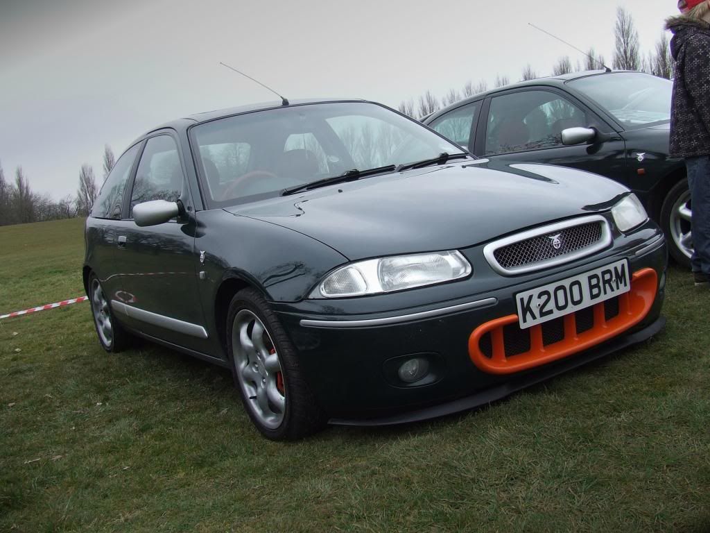
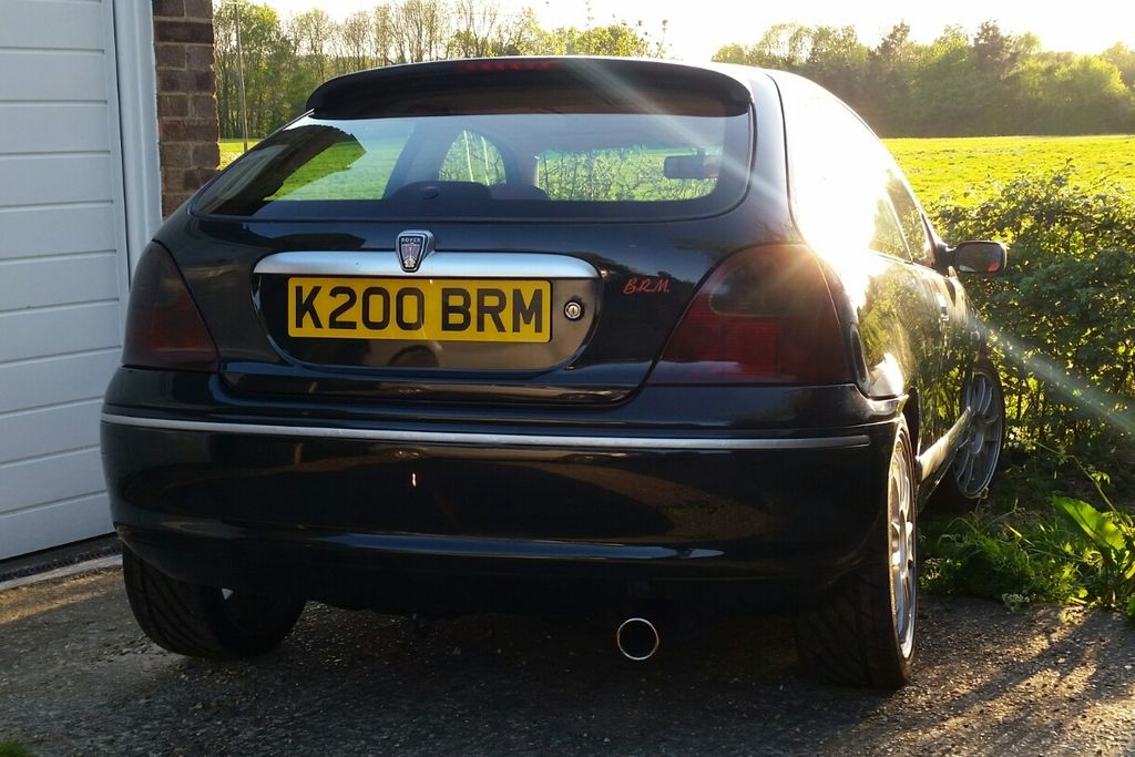
Thought I would share my project here. I've always had a soft spot for Rovers with my first car being a 1.4 200 Si. The BRM is not to everyone's taste but I love how different it is and always wanted one. I bought this one a few years ago for £600! If you're not familiar with it, it was an (arguably ill-advised) attempt by Rover to revamp the brand in this limited-run hot hatch, which was derived from the 200Vi. It has the same 143PS 1.8 VVC engine but with Torsen LSD and various cosmetic tweaks which are a nod to the BRM racing car of the 60's.
My plan is to make it better but retain road manners and driveability. It's a great car but could do with more power to back up its crazy looks. More power will require uprated brakes and suspension. More power in a K-series will require much better cooling.
The K-series has traditionally been tuned in normally aspirated form with headwork, hot cams, and throttle bodies getting you up near 200bhp. However in recent years there has been a growth in guys playing around with turbocharging the k-series. Some of you may recall Lee Conner's Elise on here powered by a K-Turbo...
So I decided to go TURBO!
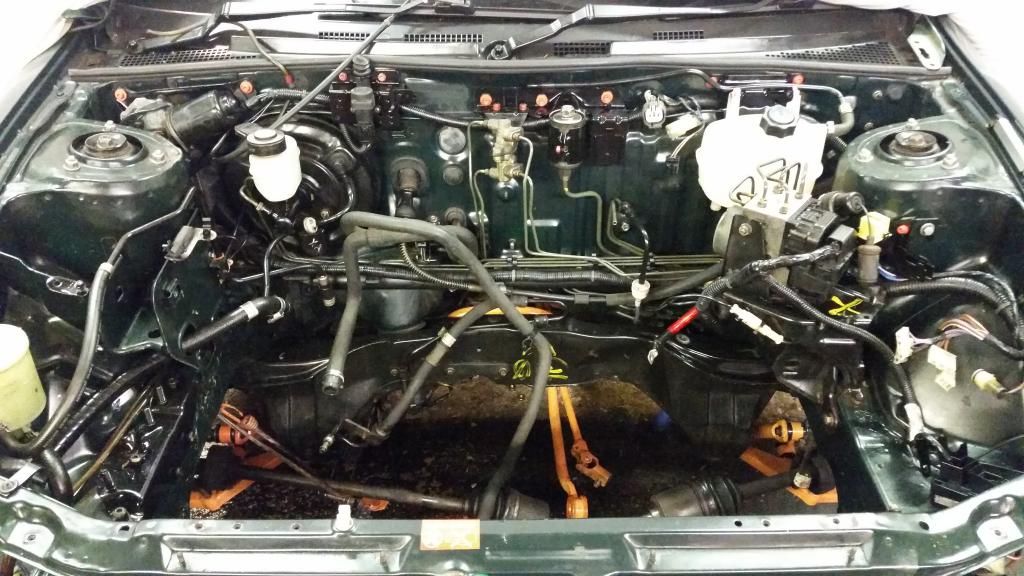
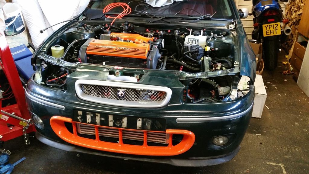
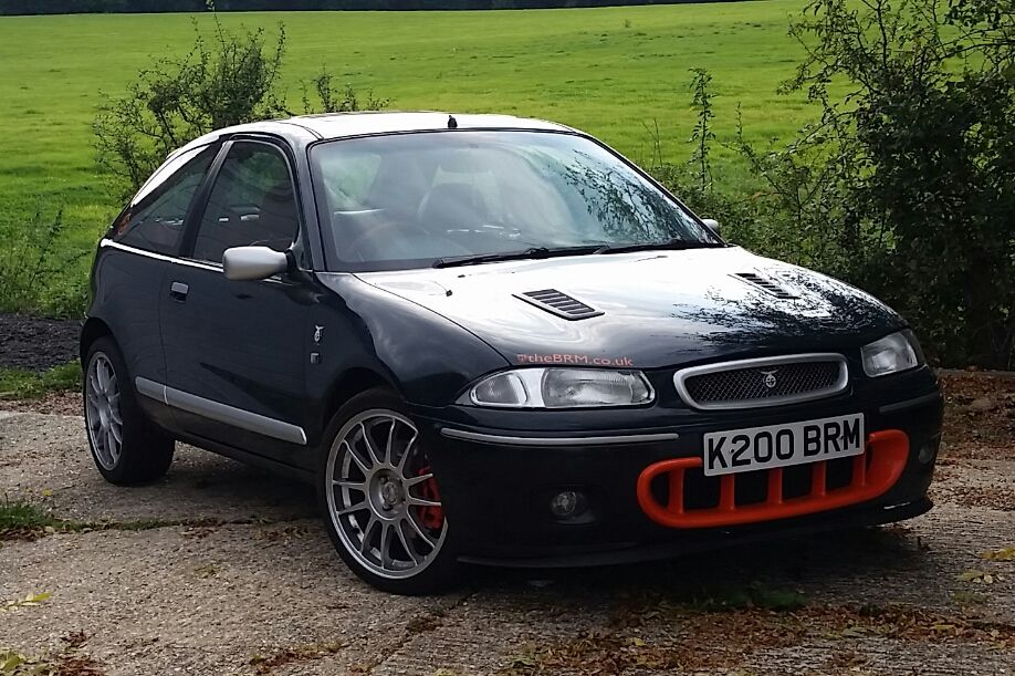
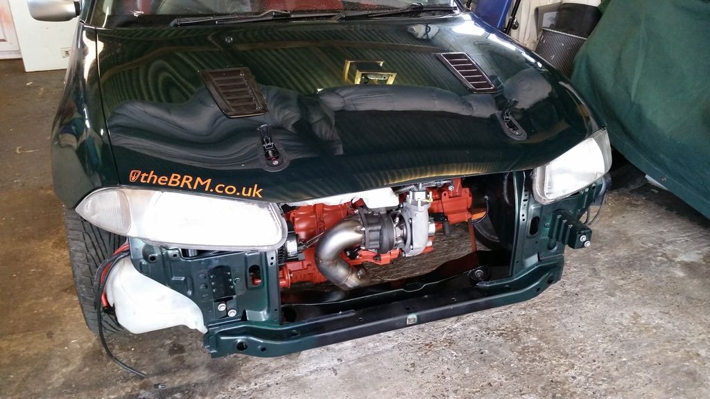
This is how the car looked before work started:
Basic spec of engine
- 1.8 k-series block
- Wossner low comp (9:1) 80mm forged pistons
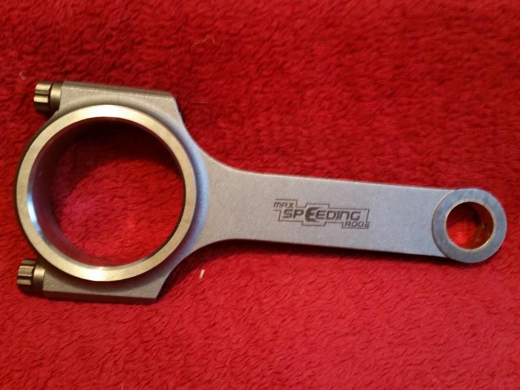
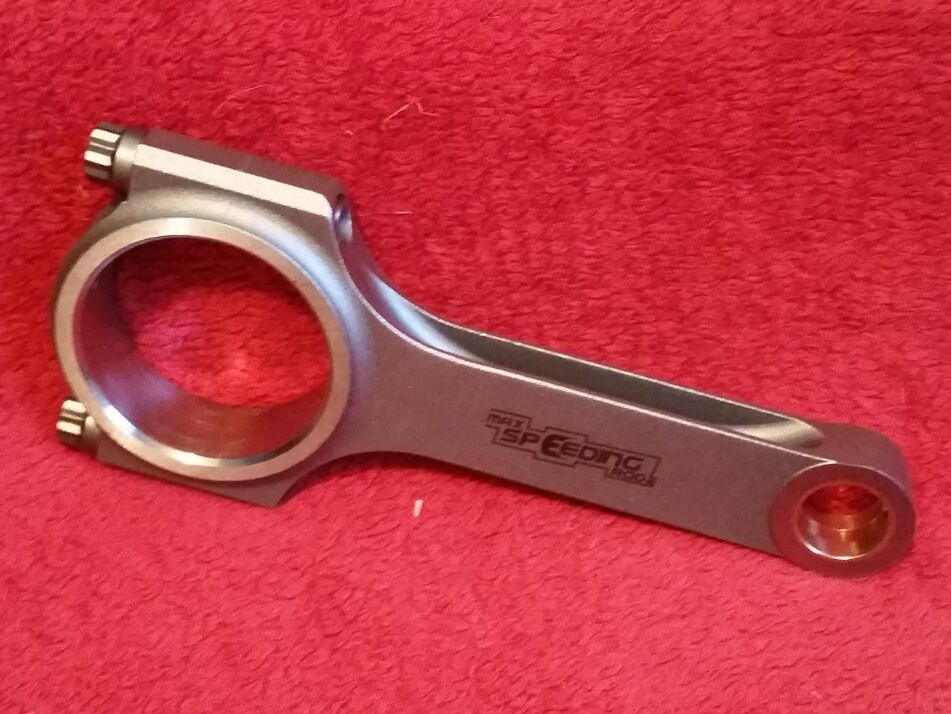
- Maxspeeding steel rods
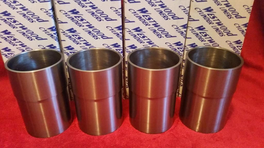
- Westwood Ductile liners
- Ported VVC head with solid cam conversion
- T28R ball-bearing turbo (from a 200SX S15) with billet comp wheel
- Emerald management
The weaknesses of the k-series are well known and it obviously has a reputation for eating head gaskets. The problem I had initially was that there are lots of unknowns. Rover made a low-boost (5psi) turbocharged 1.8 K-series which was originally for the Mexican market due to emissions regs. But it actually worked so well they used it worldwide in the Rover 75 and MG ZT. It turned out the K-series responded well to forced induction.
When it comes to aftermarket tuning with higher boost, however, So few people have turbo or supercharged the k-series (and even fewer have documented their results in detail) that I was working blind for the most part. It was clear that much more than 200bhp would probably require stronger cylinder liners, pistons and rods to be reliable long term. More than 300bhp would probably be unusable/unnecessary in a front wheel drive road car and I’d be placing other parts under stress that are difficult and/or expensive to upgrade (Crankshaft for example). Revs will be kept at a sensible 7,000rpm. So 300bhp became my upper limit, with a rough target of 250-270bhp. Not ground-breaking but the extra torque from the forced induction combined with relatively lightweight chassis and a turbo choice giving very little lag, should make for a very fun car to drive every day.
My first hurdle was to find suitable forged pistons and steel rods, as without viable upgrades the build was going nowhere. I needed a low compression ratio for forced induction. The stock 1.8T uses 2mm shorter rods to lower the CR to 9.2:1. My upgrade options were few and far between but eventually settled on Wossner pistons custom designed by Jonathan at JDM Dyno (well-known up north for tuning Elises).
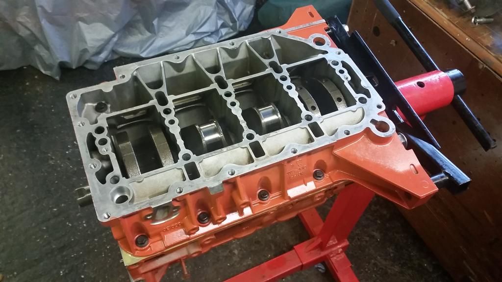
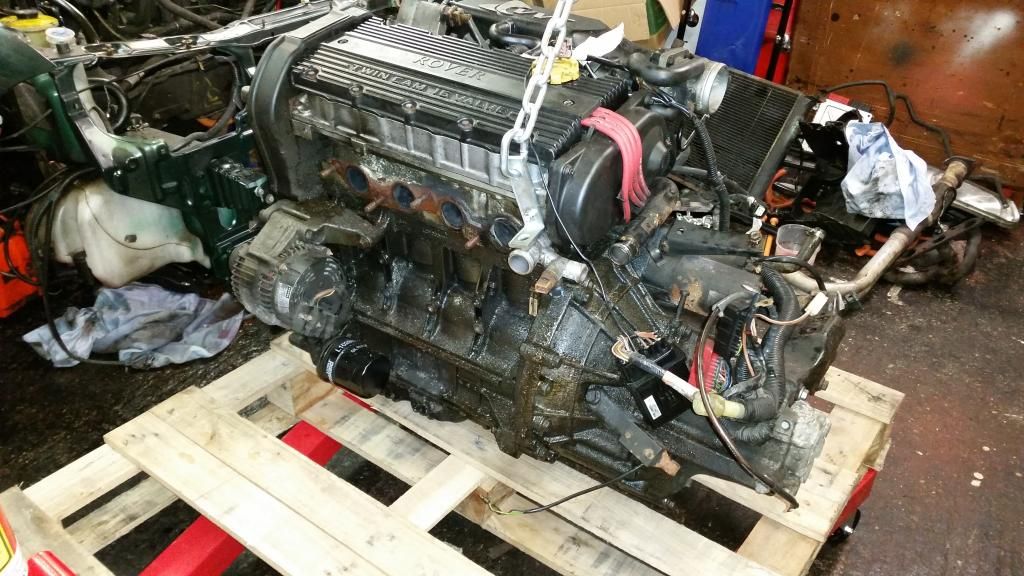
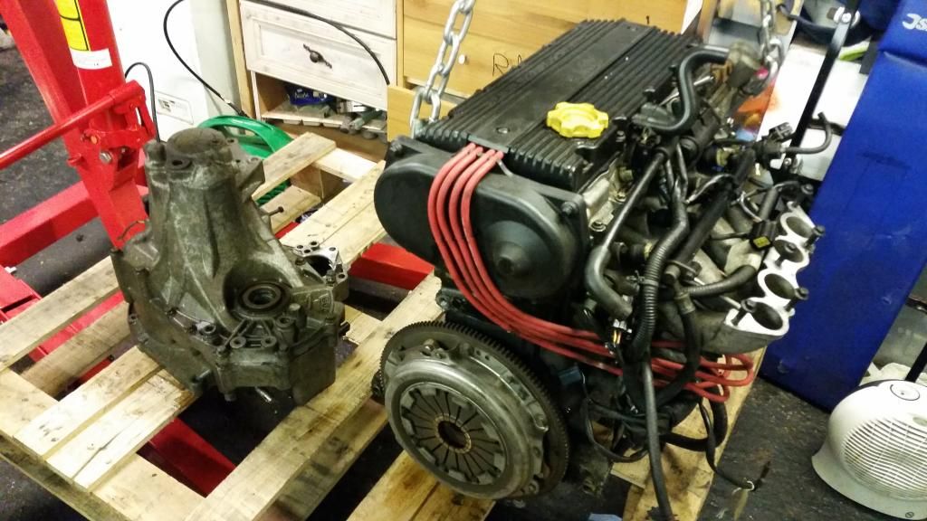
Donor engine - I started with a low-mileage turbo engine as it came with all the outside bits I would need - K-Turbo manifold, oil filter housing with the fittings for turbo feed, etc.
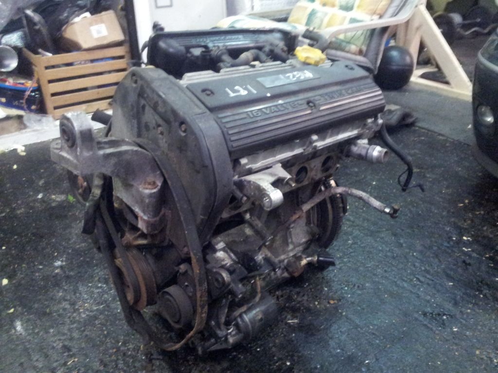
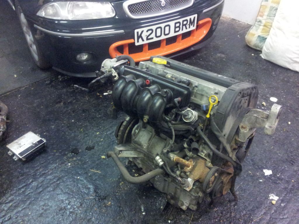
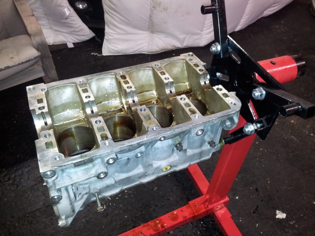
Got it up on the engine stand and started stripping it.
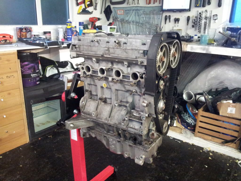
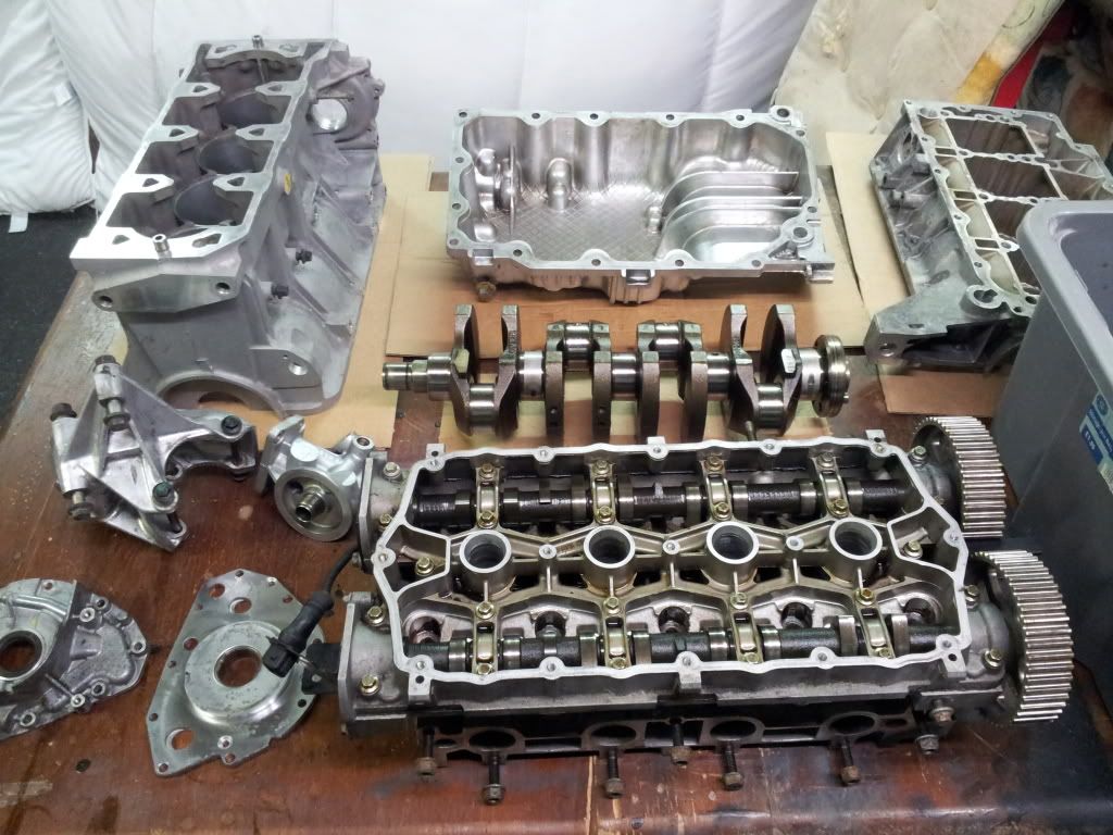
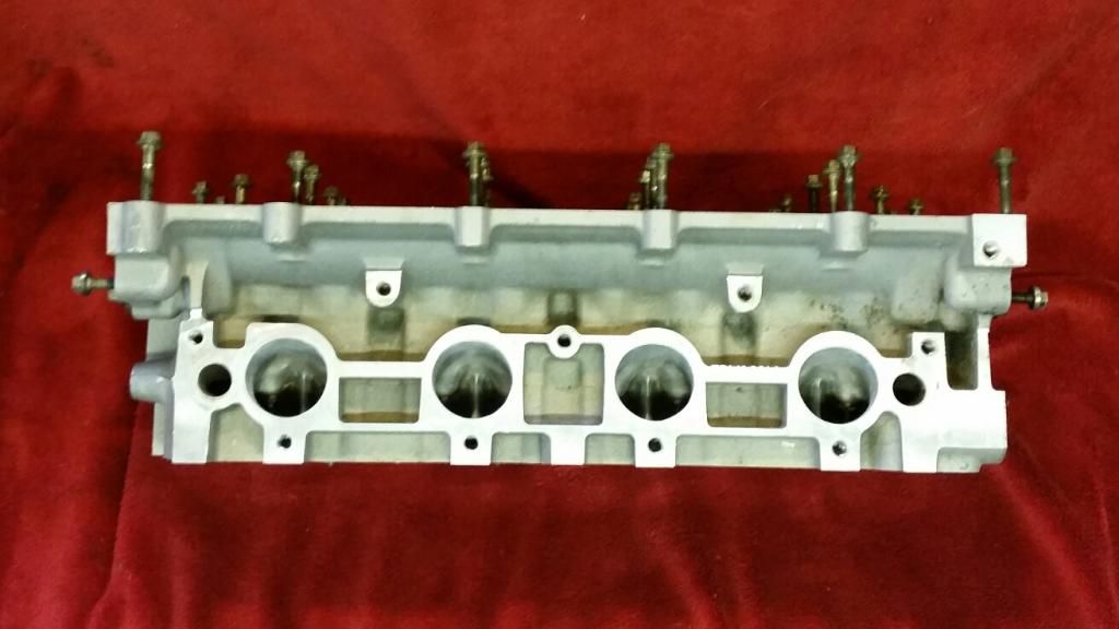
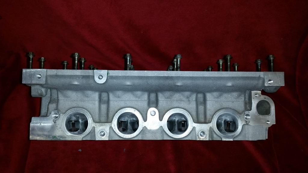
All stripped and cleaned (not using this head):
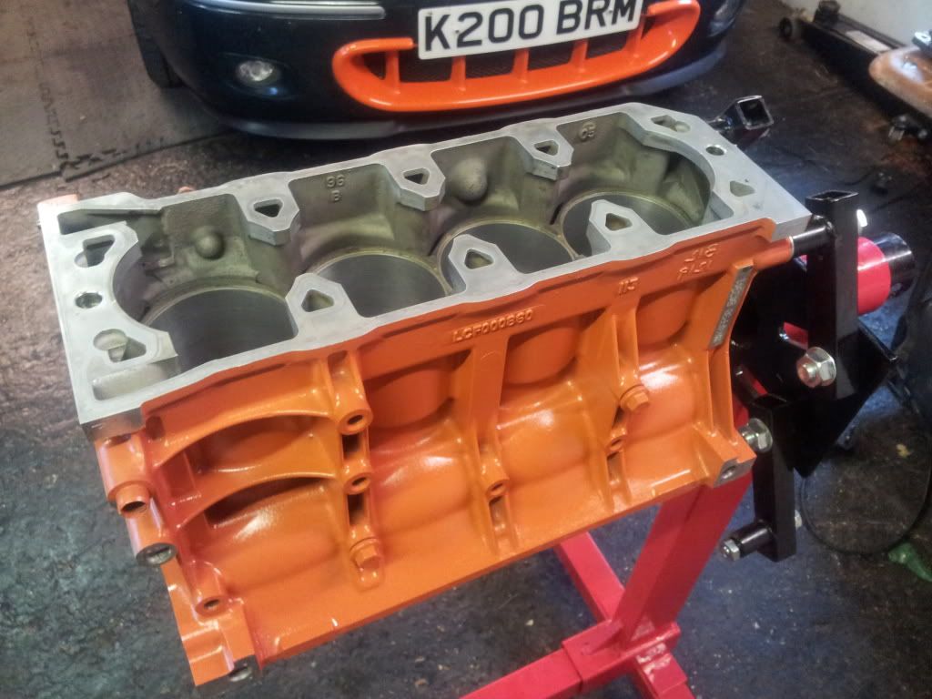
Naturally, a splash of colour:
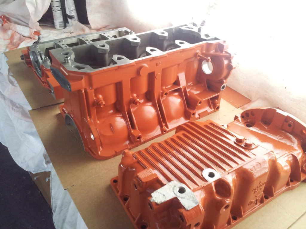
Back on the engine stand
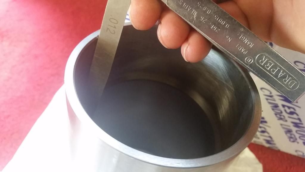
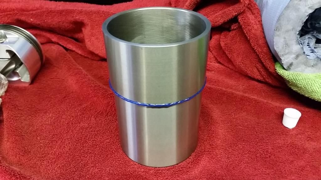
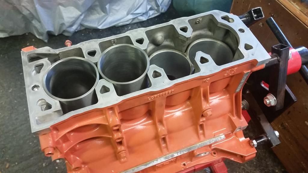
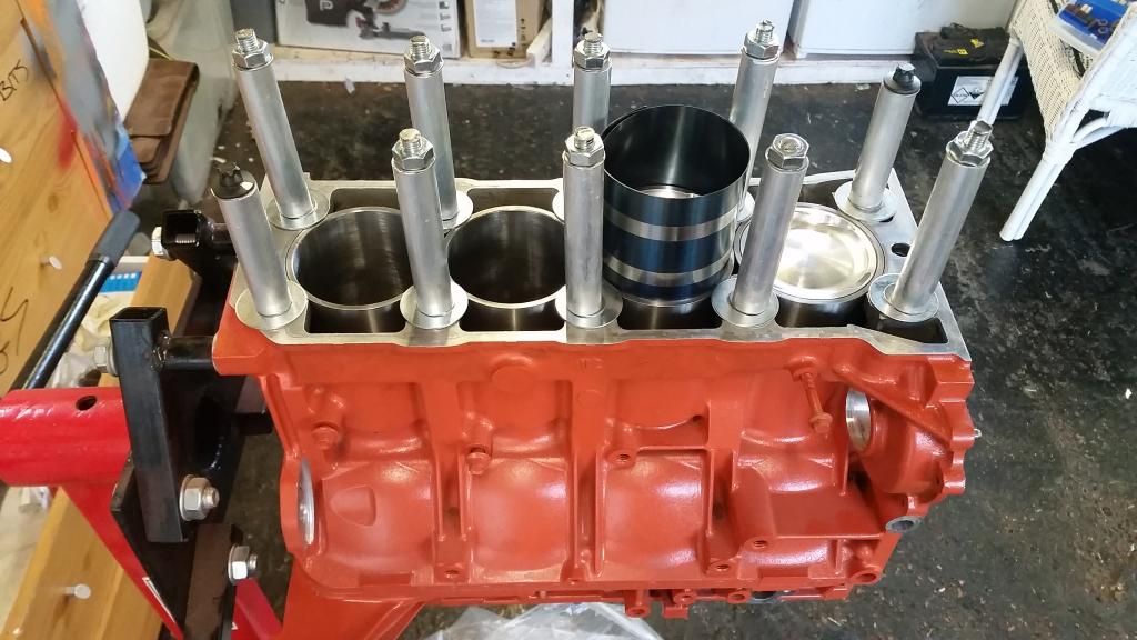
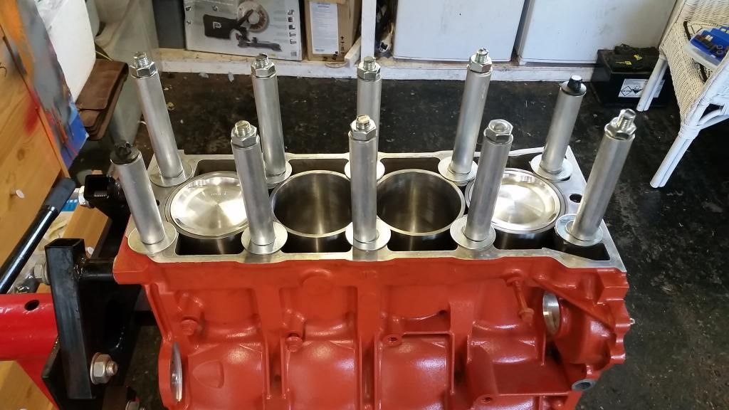
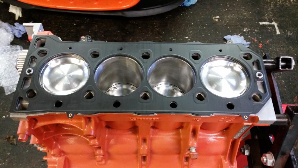
Essential for a reliable tuned k-series: Uprated liners. A few options but I went for the most robust - Westwood ductile iron liners. Liners on the 1.8 K-Series are very thin as it was not originally designed as a 1.4.
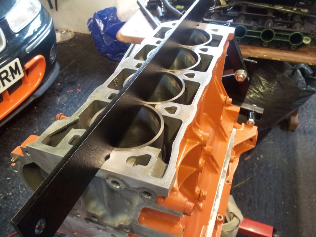
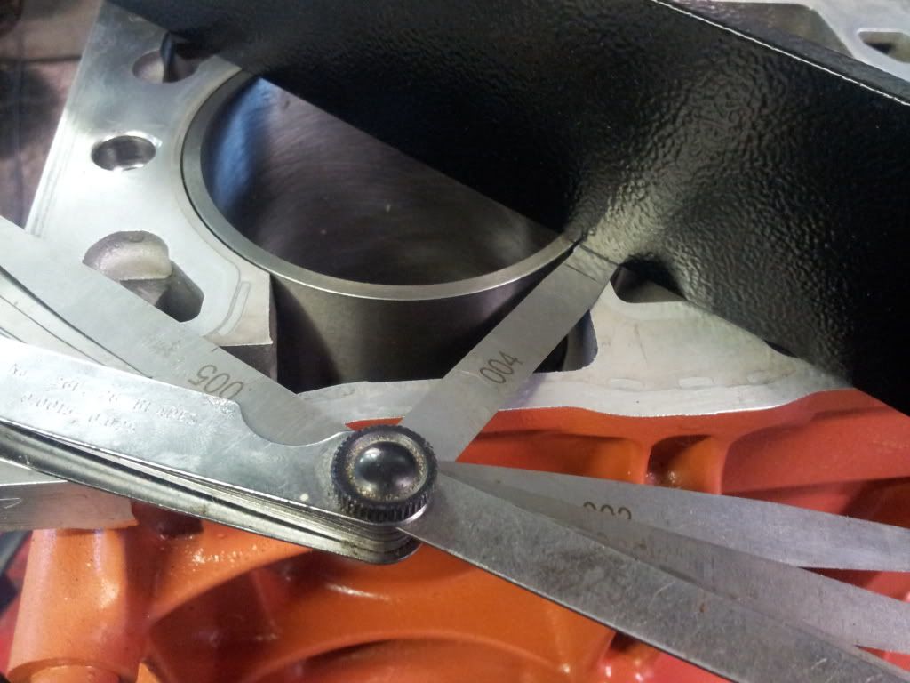
Trial fitting and measuring the stand-proud. Happily have a universal 0.004" above the deck. Bang on!
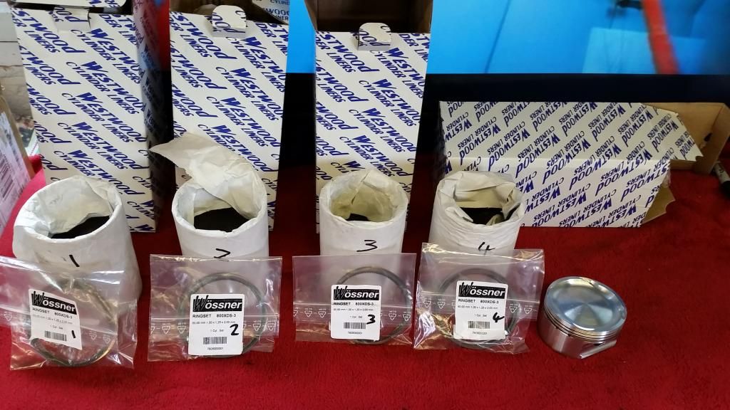
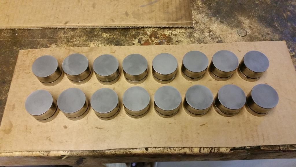
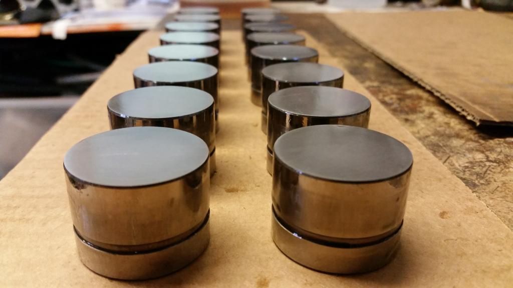
This project couldn't really get going until I got the pistons. As I said earlier there were a few options. In the end I opted for JDM Dyno designed Wossner pistons. Jon at JDM has the rights to these pistons so you can only order through him. Annoyingly, an order couldn't go through until there were several confirmed orders. I waited over a year for this to happen and in the end just ordered two sets to get it through!
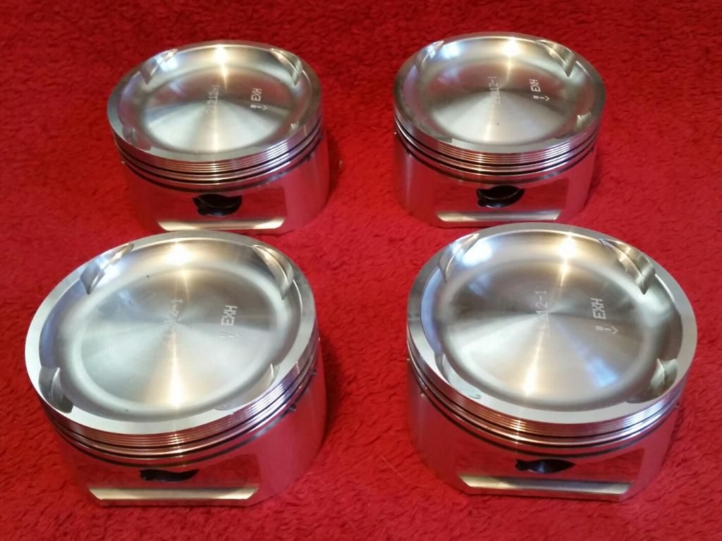
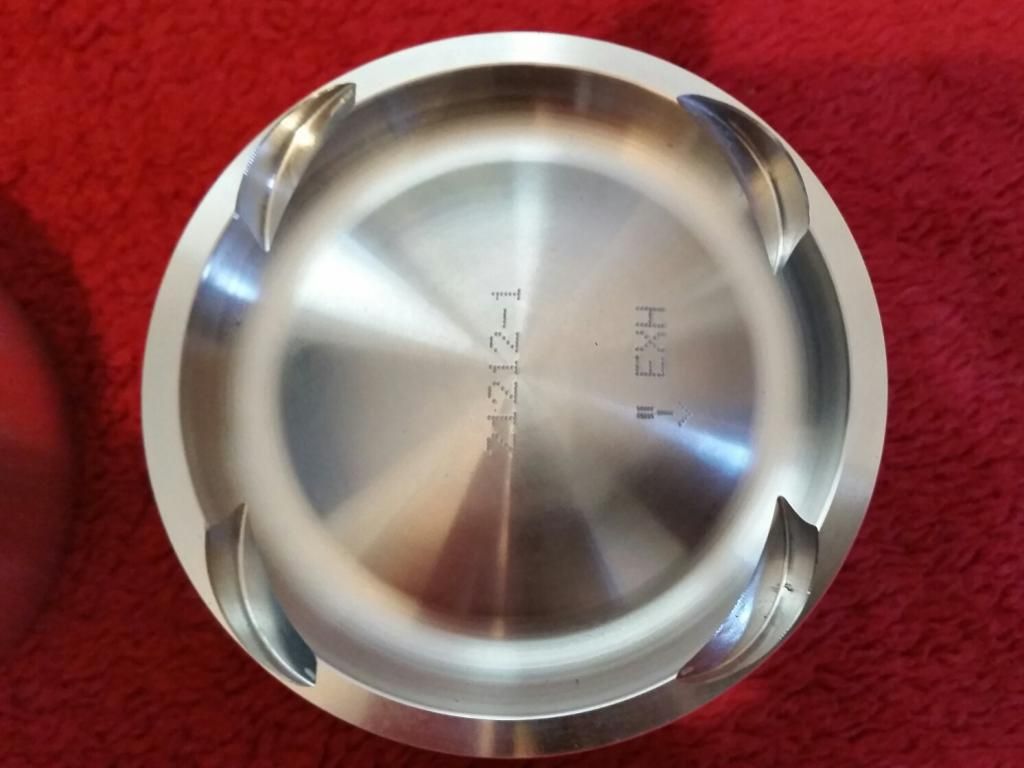
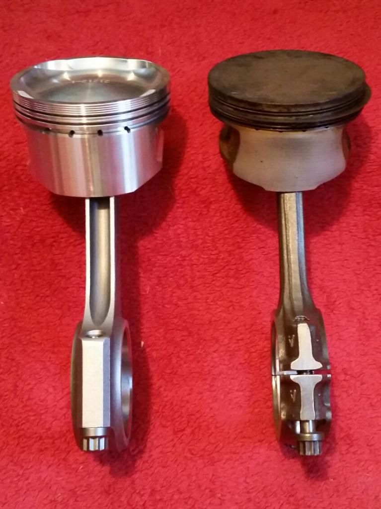
They are basically a dished piston which reduce the compression ratio to about 9:1. Big boost would require less than that (8:1) but these are designed for moderate boost (12psi) to retain good off-boost driveability. That's the idea anyway! They also retain the 18mm pin (floating).
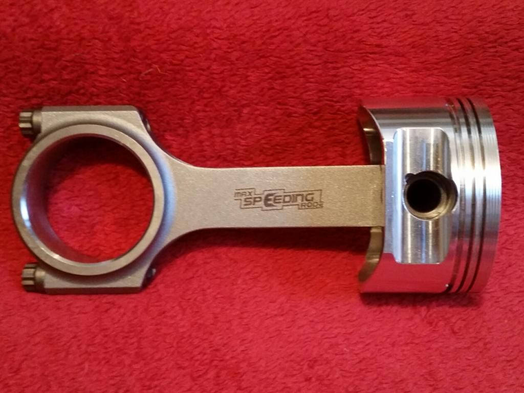
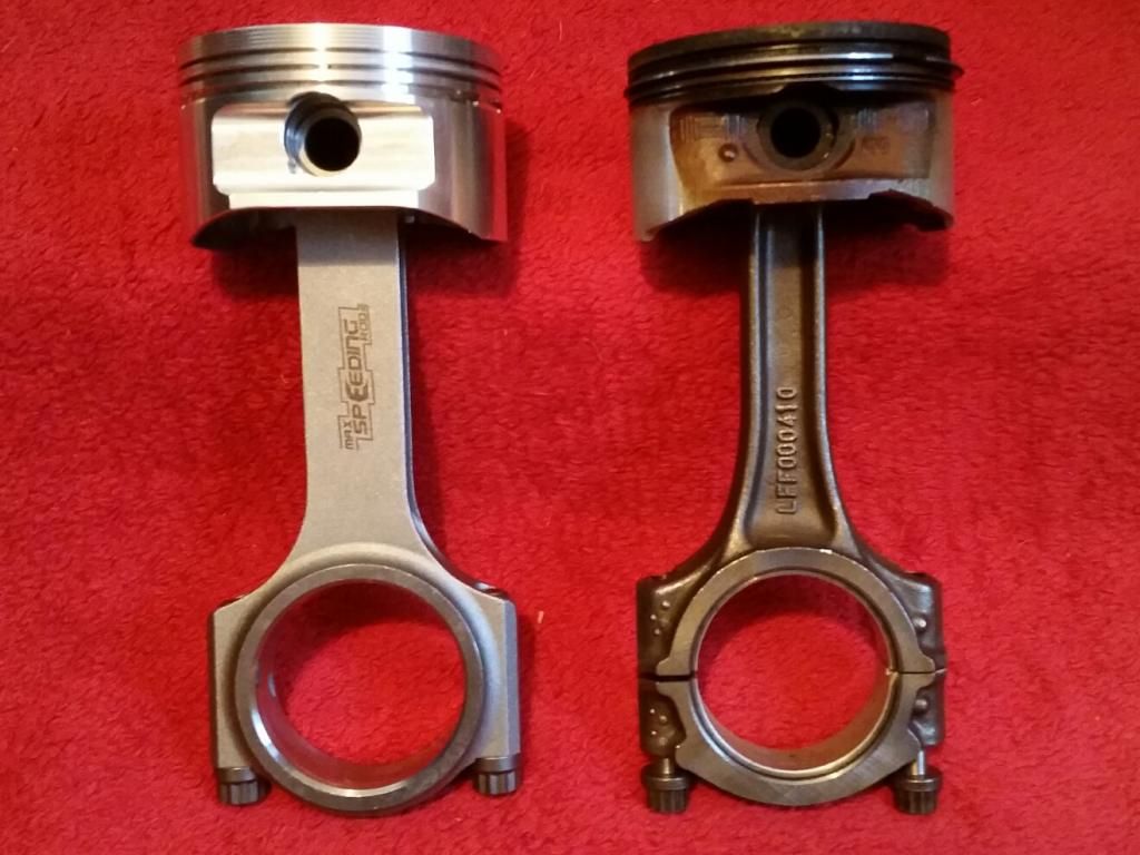
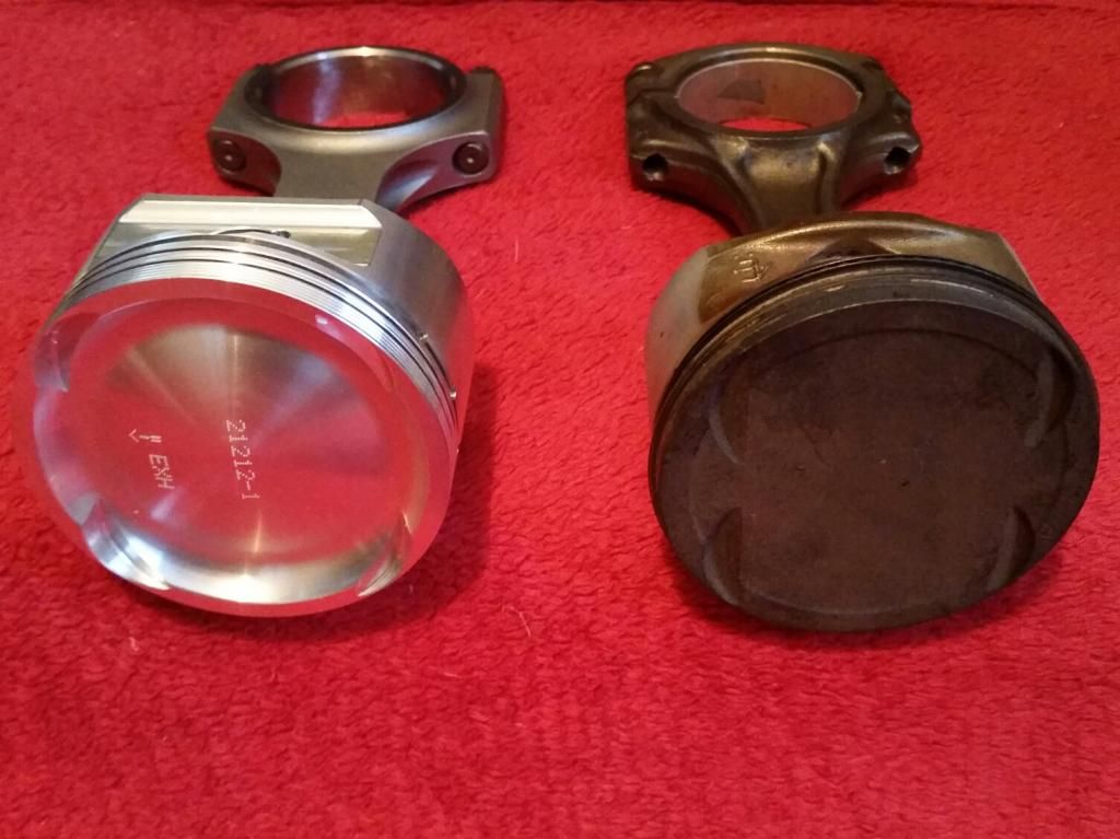
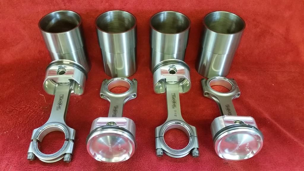
I went for Maxspeeding rods. I believe that they will be more than adequate for my purposes. I was very impressed with the build quality. I've included some side-by-side pics with the standard turbo rod and piston
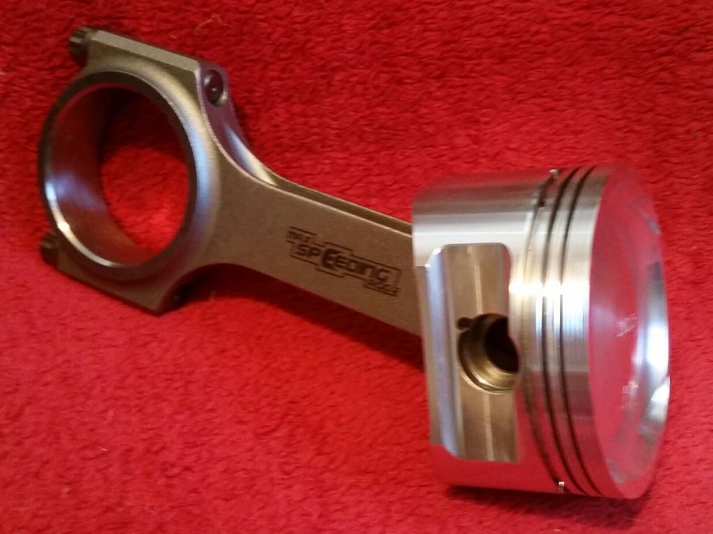
Next: Putting it together...
Thought I would share my project here. I've always had a soft spot for Rovers with my first car being a 1.4 200 Si. The BRM is not to everyone's taste but I love how different it is and always wanted one. I bought this one a few years ago for £600! If you're not familiar with it, it was an (arguably ill-advised) attempt by Rover to revamp the brand in this limited-run hot hatch, which was derived from the 200Vi. It has the same 143PS 1.8 VVC engine but with Torsen LSD and various cosmetic tweaks which are a nod to the BRM racing car of the 60's.
My plan is to make it better but retain road manners and driveability. It's a great car but could do with more power to back up its crazy looks. More power will require uprated brakes and suspension. More power in a K-series will require much better cooling.
The K-series has traditionally been tuned in normally aspirated form with headwork, hot cams, and throttle bodies getting you up near 200bhp. However in recent years there has been a growth in guys playing around with turbocharging the k-series. Some of you may recall Lee Conner's Elise on here powered by a K-Turbo...
So I decided to go TURBO!
This is how the car looked before work started:
Basic spec of engine
- 1.8 k-series block
- Wossner low comp (9:1) 80mm forged pistons
- Maxspeeding steel rods
- Westwood Ductile liners
- Ported VVC head with solid cam conversion
- T28R ball-bearing turbo (from a 200SX S15) with billet comp wheel
- Emerald management
The weaknesses of the k-series are well known and it obviously has a reputation for eating head gaskets. The problem I had initially was that there are lots of unknowns. Rover made a low-boost (5psi) turbocharged 1.8 K-series which was originally for the Mexican market due to emissions regs. But it actually worked so well they used it worldwide in the Rover 75 and MG ZT. It turned out the K-series responded well to forced induction.
When it comes to aftermarket tuning with higher boost, however, So few people have turbo or supercharged the k-series (and even fewer have documented their results in detail) that I was working blind for the most part. It was clear that much more than 200bhp would probably require stronger cylinder liners, pistons and rods to be reliable long term. More than 300bhp would probably be unusable/unnecessary in a front wheel drive road car and I’d be placing other parts under stress that are difficult and/or expensive to upgrade (Crankshaft for example). Revs will be kept at a sensible 7,000rpm. So 300bhp became my upper limit, with a rough target of 250-270bhp. Not ground-breaking but the extra torque from the forced induction combined with relatively lightweight chassis and a turbo choice giving very little lag, should make for a very fun car to drive every day.
My first hurdle was to find suitable forged pistons and steel rods, as without viable upgrades the build was going nowhere. I needed a low compression ratio for forced induction. The stock 1.8T uses 2mm shorter rods to lower the CR to 9.2:1. My upgrade options were few and far between but eventually settled on Wossner pistons custom designed by Jonathan at JDM Dyno (well-known up north for tuning Elises).
Donor engine - I started with a low-mileage turbo engine as it came with all the outside bits I would need - K-Turbo manifold, oil filter housing with the fittings for turbo feed, etc.
Got it up on the engine stand and started stripping it.
All stripped and cleaned (not using this head):
Naturally, a splash of colour:
Back on the engine stand
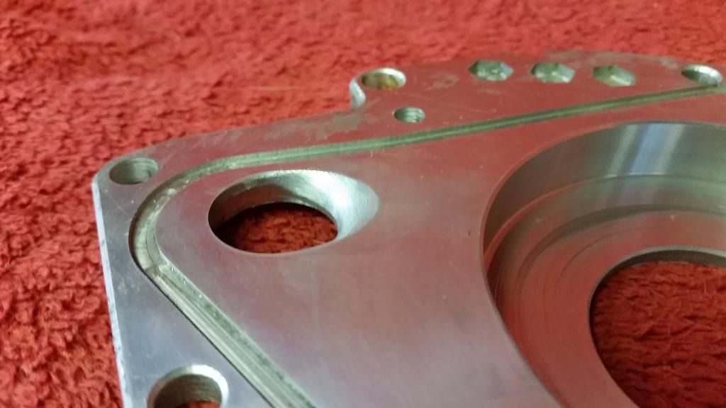
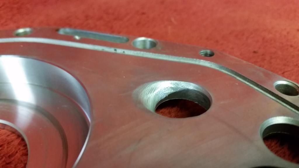
Essential for a reliable tuned k-series: Uprated liners. A few options but I went for the most robust - Westwood ductile iron liners. Liners on the 1.8 K-Series are very thin as it was not originally designed as a 1.4.
Trial fitting and measuring the stand-proud. Happily have a universal 0.004" above the deck. Bang on!
This project couldn't really get going until I got the pistons. As I said earlier there were a few options. In the end I opted for JDM Dyno designed Wossner pistons. Jon at JDM has the rights to these pistons so you can only order through him. Annoyingly, an order couldn't go through until there were several confirmed orders. I waited over a year for this to happen and in the end just ordered two sets to get it through!
They are basically a dished piston which reduce the compression ratio to about 9:1. Big boost would require less than that (8:1) but these are designed for moderate boost (12psi) to retain good off-boost driveability. That's the idea anyway! They also retain the 18mm pin (floating).
I went for Maxspeeding rods. I believe that they will be more than adequate for my purposes. I was very impressed with the build quality. I've included some side-by-side pics with the standard turbo rod and piston
Next: Putting it together...
Edited by Stuballs on Monday 7th August 09:17
Had the whole bottom end balanced by Vibration Free. Intetesting results:
Crankshaft was way outside of factory tolerance (apparently supposed to be within 40gmm). It was109gmm at the pulley end and 368gmm at the flywheel end! Now down to 30gmm at both ends. No explanation for why it was so out. Apparently on later engines from Rover the tolerances went out the window.
Flywheel
Before: 324gmm
After: 6.6gmm
Clutch cover (Borg and Beck)
Before: 733gmm (!!!)
After: 28gmm
Pulley
Before: 342gmm
After: 17.2gmm
Pistons were within 0.8g and rods were within 0.7g. Now matched.
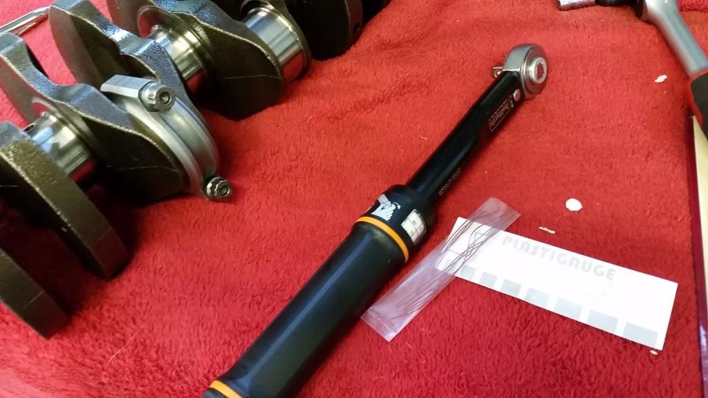
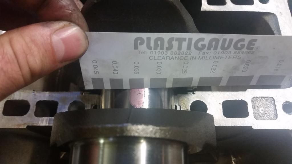
Now to check clearances before the final rebuild. Time to get busy with the plastigauge...
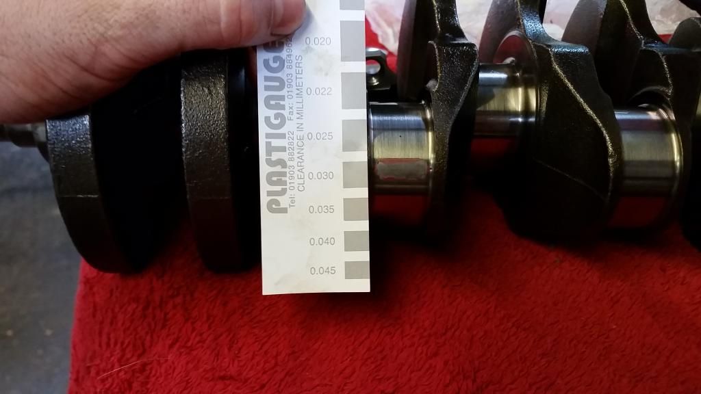
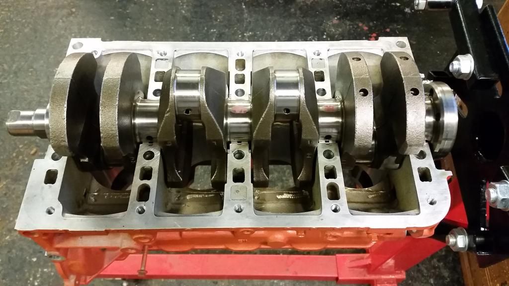
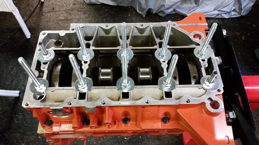
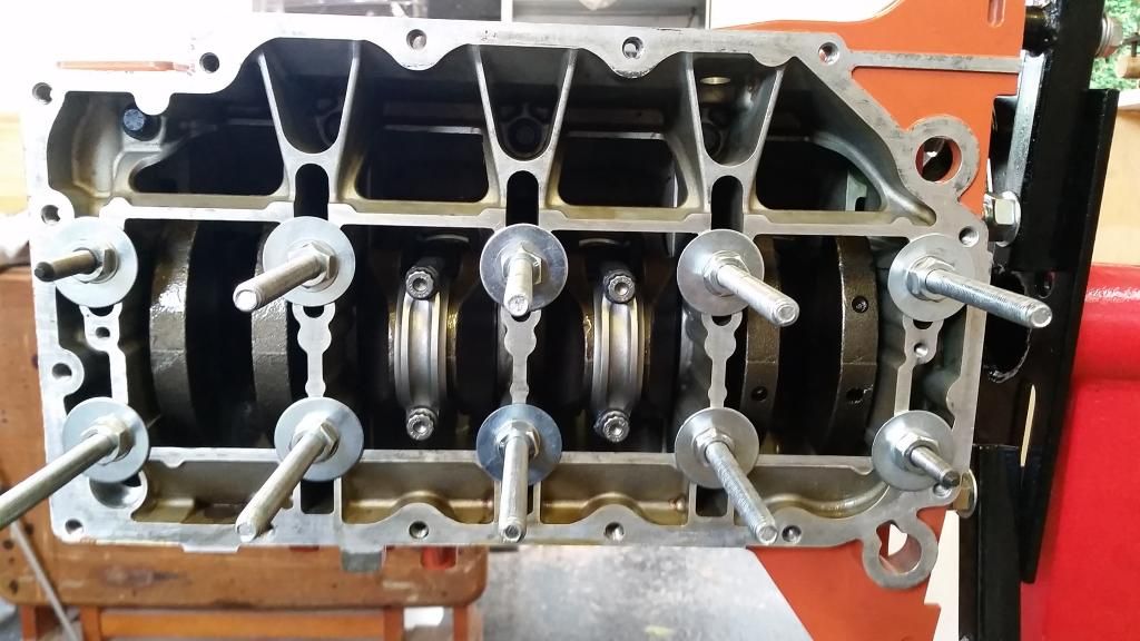
Balanced crank installed with shiny new main bearings.
A few bits ready to go in.
Measuring ring gaps
Rings on pistons and pistons on rods, with shiny new big end bearings.
Westwood ductile iron liners ready to seat with a bead of Hylomar blue.
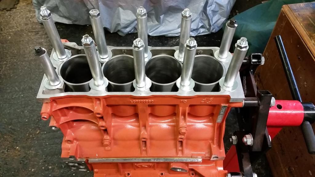
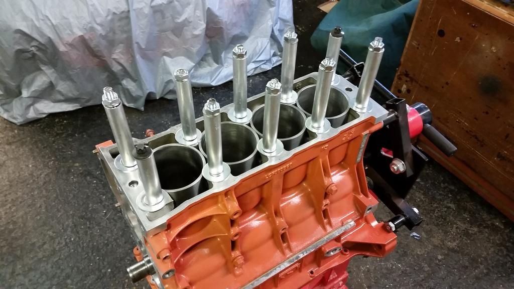
Liners going in
Liners clamped in with my DIY liner clamps. Probably overkill but I thought I was going to have to turn the crank to get the big ends bolted up, and you're not supposed to turn the crank without the head torqued down!
At this point I got a bit paranoid about piston ring gaps so went back to double check. Wossner provide conflicting information on their ring gaps. When I checked the first time the info I found suggested 0.2mm - 0.35mm. However I then found a guide on their website suggesting around twice that. I went with the latter to be safe. So most of the rings had to come back off the pistons to be gapped!
Filing with a metal file was getting me nowhere. Rings are made of incredibly hard material! 20 minutes on one ring didn't get me anywhere. So I rigged up a tiny dremel grinding wheel in my drill and had it spinning very slowly. Worked a treat!
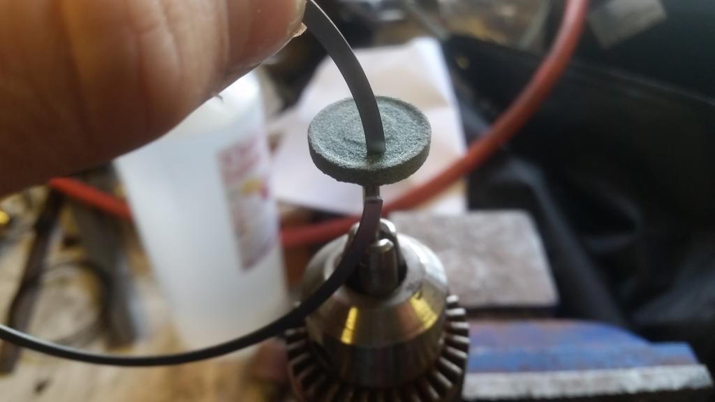
A time consuming process and you have to be so careful not the scratch the (very expensive) liners putting the rings in for measuring.
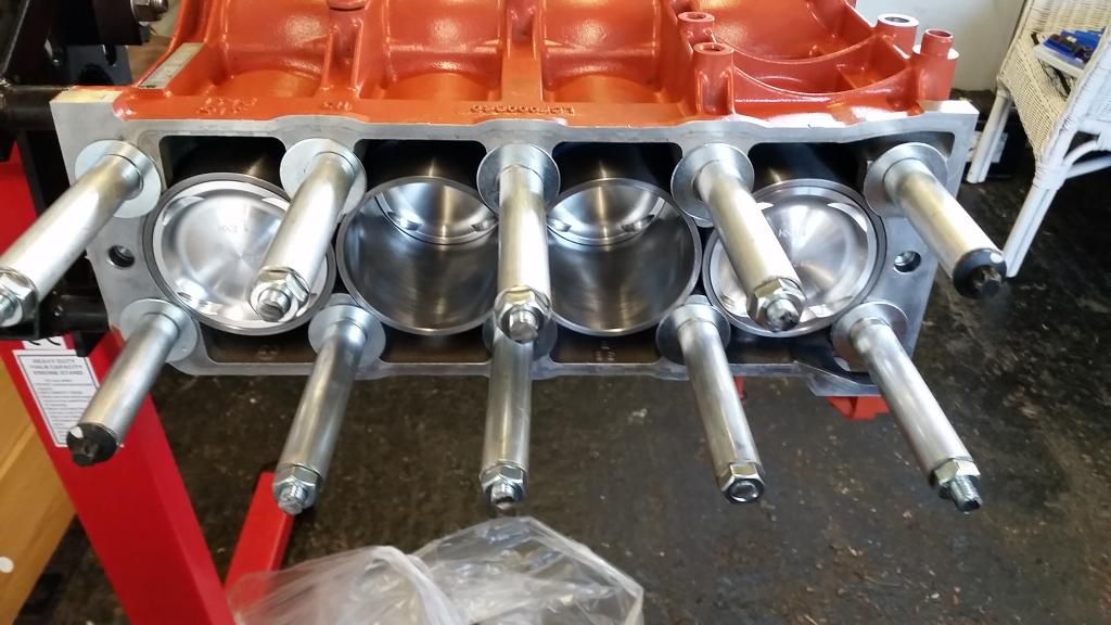
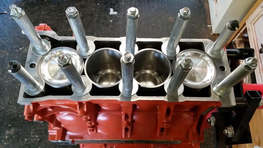
So now I can finally getting the pistons and rods in! I expected to have to turn the crank 180 degrees to get 2 and 3 big end caps bolted up, but I had access to all 4 with the crank at TDC, so didn't bother.
First time using a piston ring clamp. It's virtually impossible to keep the rings still whilst clamping up. Hopefully they stayed more or less where they should be!
All in!
Crankshaft was way outside of factory tolerance (apparently supposed to be within 40gmm). It was109gmm at the pulley end and 368gmm at the flywheel end! Now down to 30gmm at both ends. No explanation for why it was so out. Apparently on later engines from Rover the tolerances went out the window.
Flywheel
Before: 324gmm
After: 6.6gmm
Clutch cover (Borg and Beck)
Before: 733gmm (!!!)
After: 28gmm
Pulley
Before: 342gmm
After: 17.2gmm
Pistons were within 0.8g and rods were within 0.7g. Now matched.
Now to check clearances before the final rebuild. Time to get busy with the plastigauge...
Balanced crank installed with shiny new main bearings.
A few bits ready to go in.
Measuring ring gaps
Rings on pistons and pistons on rods, with shiny new big end bearings.
Westwood ductile iron liners ready to seat with a bead of Hylomar blue.
Liners going in
Liners clamped in with my DIY liner clamps. Probably overkill but I thought I was going to have to turn the crank to get the big ends bolted up, and you're not supposed to turn the crank without the head torqued down!
At this point I got a bit paranoid about piston ring gaps so went back to double check. Wossner provide conflicting information on their ring gaps. When I checked the first time the info I found suggested 0.2mm - 0.35mm. However I then found a guide on their website suggesting around twice that. I went with the latter to be safe. So most of the rings had to come back off the pistons to be gapped!
Filing with a metal file was getting me nowhere. Rings are made of incredibly hard material! 20 minutes on one ring didn't get me anywhere. So I rigged up a tiny dremel grinding wheel in my drill and had it spinning very slowly. Worked a treat!
A time consuming process and you have to be so careful not the scratch the (very expensive) liners putting the rings in for measuring.
So now I can finally getting the pistons and rods in! I expected to have to turn the crank 180 degrees to get 2 and 3 big end caps bolted up, but I had access to all 4 with the crank at TDC, so didn't bother.
First time using a piston ring clamp. It's virtually impossible to keep the rings still whilst clamping up. Hopefully they stayed more or less where they should be!
All in!
Edited by Stuballs on Wednesday 4th October 14:03
AdamIndy said:
A tuner I used to know swore blind that using a multi later steel gasket and ARP stud conversion would cure the HG failure for good.
I'll be using the so called "n-series" gasket developed by SAIC for the kavachi engine. It's a 6 layer mls gasket. It's to be used in conjunction with higher tensile bolts (head 10.9 vs the old 9.8) and strengthened lower oil rail. The strengthened oil rail (which is the bottom of the "sandwich" the stretch head bolts bolt into, was developed to limit torsional flex of the engine and is one piece in the head gasket failure puzzle).I prefer not to use studs and nuts because the aluminum block and head are one big sandwich with the cylinder liners pressing the gasket against the head. Every time it heats up and expands the oe stretch bolts expand a bit too. Using studs with much less stretch will increase the load on the fire rings and in the liner seats.
Also, the load on the main bearings is determined by that clamping force. It's so important in fact you can't turn the crank without the head on and properly torqued down. I don't like the idea of messing with that design.
It's a lot of theory though and I accept a few others have done it without issue. I just didn't want to stray too far from the original design and instead focus on just improving how it works and fixing other things. For example, using a pressure relief thermostat at the engine exit to avoid thermal shock the oe setup suffers from (where the thermostat is at the entrance to the engine right by cylinder 1)
Mr Teddy Bear said:
How did you tighten the nuts on your home made liner clamp Stu ?
Also those balance tolerance figures that you quote from Vibration Free, is that static or a dynamic form of balancing ?
Tightened in accordance with the head bolt tightening procedure, but more gradually. Also those balance tolerance figures that you quote from Vibration Free, is that static or a dynamic form of balancing ?
It was all dynamically balanced.
Thanks guys
I want to keep the stock look as much as I can. That said, the previous owner did de-chrome the grill and sprayed it the same "sparkle silver" as the rest of the trim. I quite like that.
Seats could be more supportive but this will be a road car so I'm not too worried. The interior is one of the BRM's style points (love it or hate it) so it would be a shame to lose that for some aftermarket bucket seats. But if this was a track car I'd have no choice.

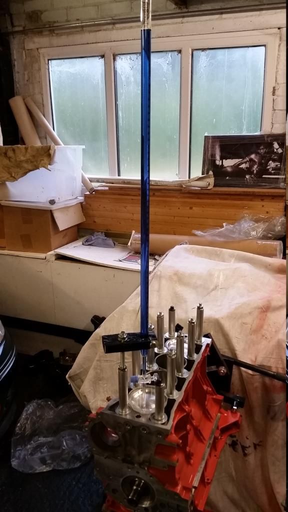
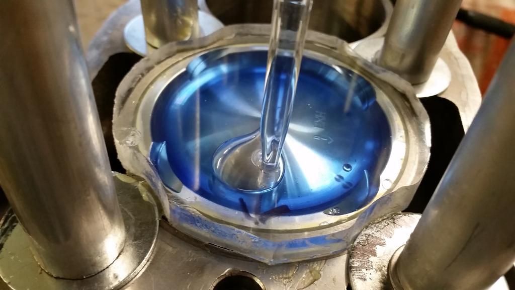
I thought I had better check my static compression ratio. The piston supplier told me they lower the compression ratio to about 9:1, but I wanted to measure it for myself. There are other variables involved so having a base reading will help me decide what direction to go on other aspects of the build (headwork, gasket choice).
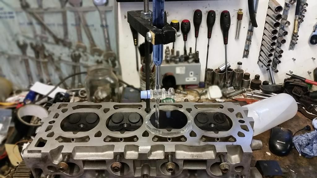
The process:
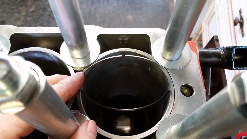
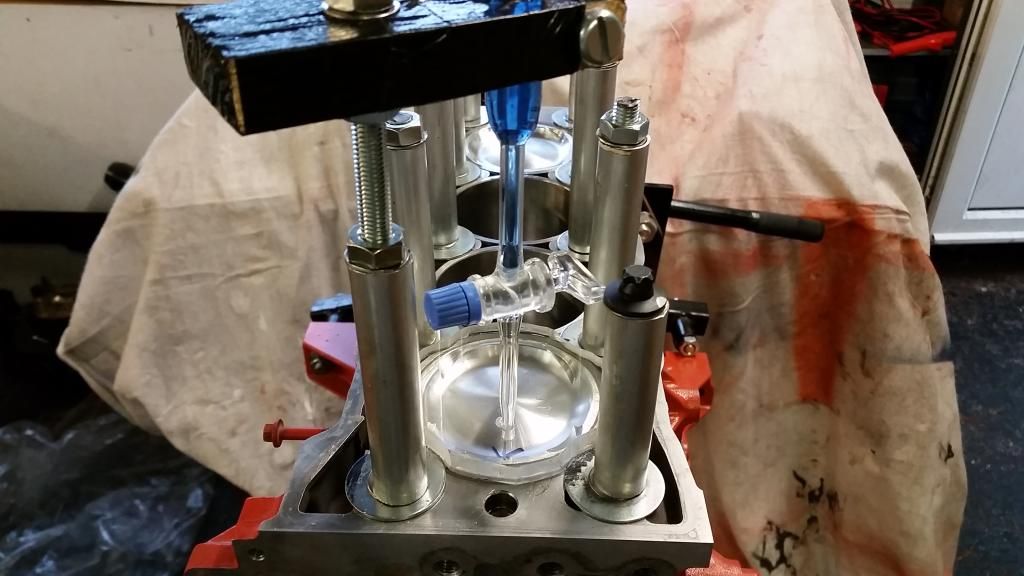
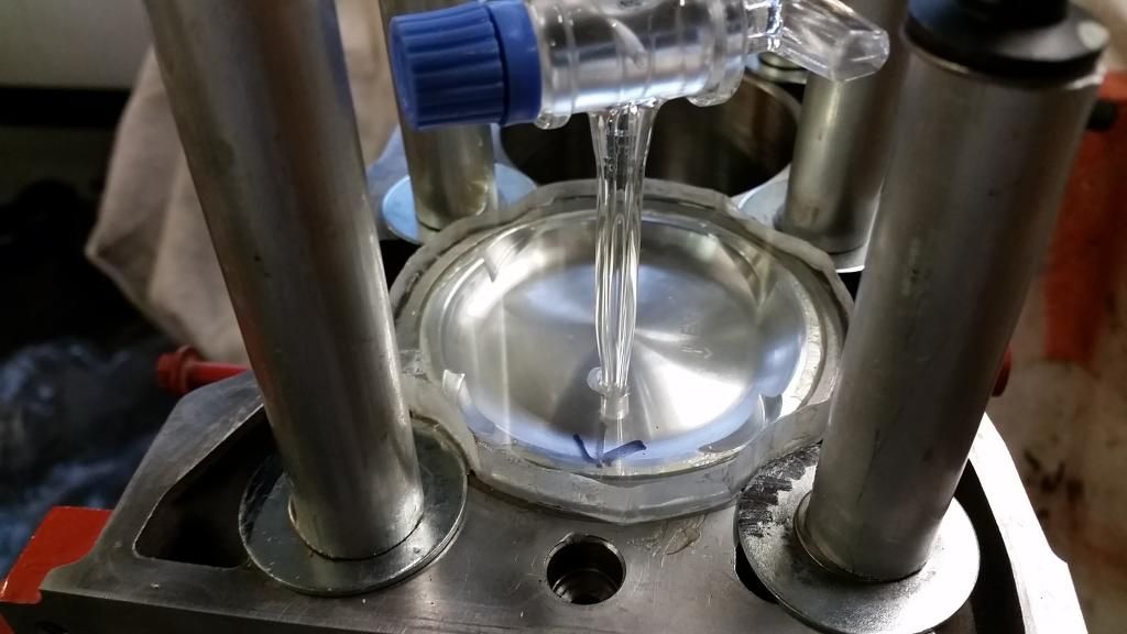
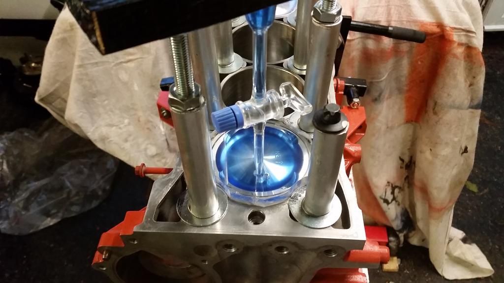
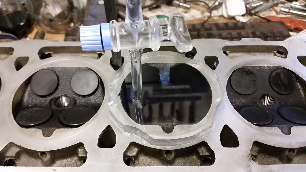
I got a cheap burette (A-Level Chemistry comes screaming back to me) and a 10mm thick acrylic plate off ebay. The idea is that you sit the acrylic plate on the liner (sealed with some grease), then dribble a measured amount of fluid through a hole in it until it reaches the top of the plate. For the fluid I used rubbing alcohol with blue food dye in it. Obviously the cylinder you're measuring has to be at TDC.
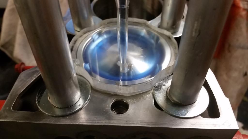
Starting with the piston top:
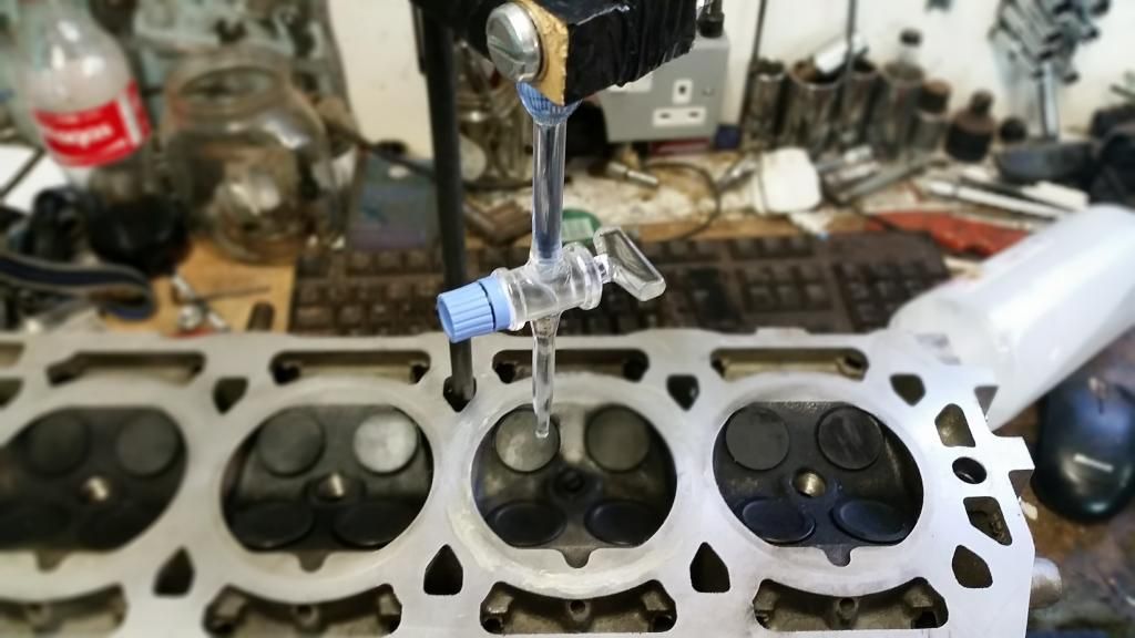
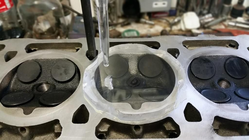
And moving onto the cylinder head:
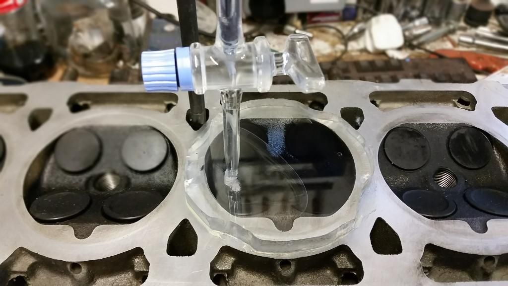
Results:
Volume above piston (to flush with liner): 16.4cc
Combustion chamber: 30.2cc
I know the piston swept volume is 448.9cc
If we assume a 1mm thick compressed head gasket, the volume of that is 5cc
Note: with this method I have probably not measured the volume above the first compression ring, but below the piston deck. This amount is probably well under 1cc so I'm not too concerned.
Volume at BDC / Volume at TDC = 500.5/51.6 = 9.7
These figures give a compression ratio of 9.7:1
This exercise has highlighted how dramatic material removal from the combustion chamber from headwork can be. You can reportedly remove up to 6cc from the VVC head's combustion chamber. Removing this much would reduce CR to 8.8.
What I found interesting was how little relative effect a skim would have. The maximum recommended 0.2mm skim would reduce the combustion chamber by less than 1cc (on my figures increasing CR from 9.7 to 9.9:1).
The process:
I got a cheap burette (A-Level Chemistry comes screaming back to me) and a 10mm thick acrylic plate off ebay. The idea is that you sit the acrylic plate on the liner (sealed with some grease), then dribble a measured amount of fluid through a hole in it until it reaches the top of the plate. For the fluid I used rubbing alcohol with blue food dye in it. Obviously the cylinder you're measuring has to be at TDC.
Starting with the piston top:
And moving onto the cylinder head:
Results:
Volume above piston (to flush with liner): 16.4cc
Combustion chamber: 30.2cc
I know the piston swept volume is 448.9cc
If we assume a 1mm thick compressed head gasket, the volume of that is 5cc
Note: with this method I have probably not measured the volume above the first compression ring, but below the piston deck. This amount is probably well under 1cc so I'm not too concerned.
Volume at BDC / Volume at TDC = 500.5/51.6 = 9.7
These figures give a compression ratio of 9.7:1
This exercise has highlighted how dramatic material removal from the combustion chamber from headwork can be. You can reportedly remove up to 6cc from the VVC head's combustion chamber. Removing this much would reduce CR to 8.8.
What I found interesting was how little relative effect a skim would have. The maximum recommended 0.2mm skim would reduce the combustion chamber by less than 1cc (on my figures increasing CR from 9.7 to 9.9:1).
Edited by Stuballs on Wednesday 4th October 14:05
turbotoaster said:
eeek 9.7:1 thats not great news if I want to throw 28psi of boost through it to make the 400bhp, looks like im going to have to make sure I take some material out of the head and maybe run a ferriday head saver to give it a little more of a drop, thanks for checking this
Hi LeeIf you take 5 or 6cc out of the top of the combustion chamber even with a 1mm elastomer gasket you'll get to around 9:1. If you use an MLS or the n-series gasket you'll get closer to 8.5 or 8:1.
An alternative would be to source the maxspeeding turbo spec rods (2mm shorter?). That'll take you below 8:1 for really high boost.
Alias218 said:
I remember cc'ing the head and combustion chamber during my apprenticeship. I hated it. The tap on the pipette was so fiddly and fragile - I was terrified I would knock it off it's perch and flood the floor with red fluid!
Another secret admirer of the BRM here - looking forward to seeing this progress.
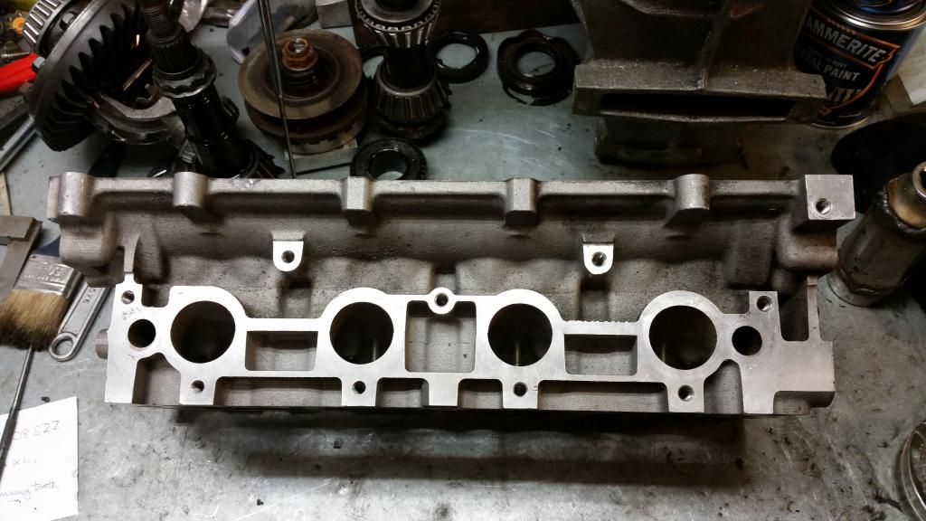
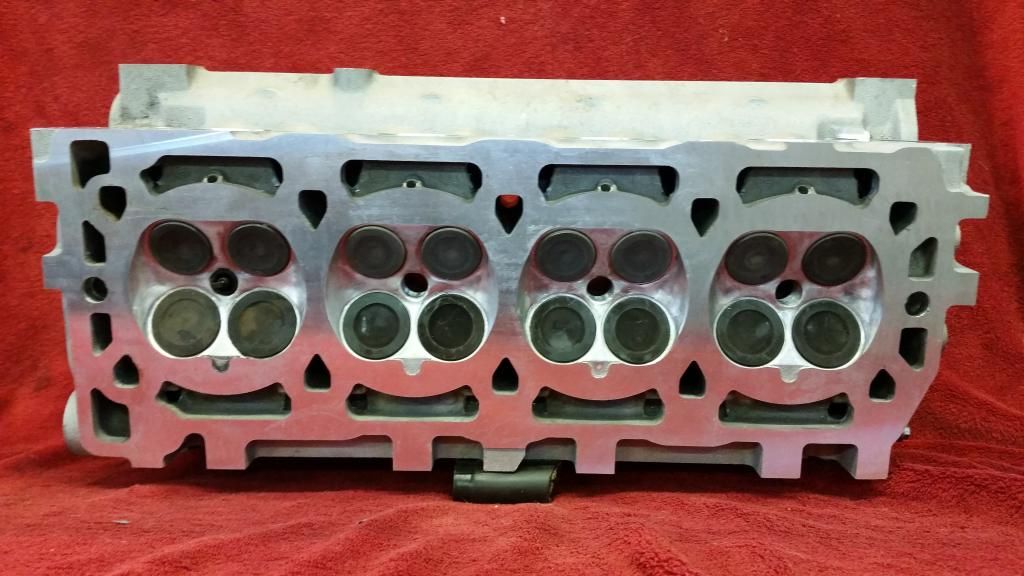
That's exactly what happened the second time I tried to measure the head volume when I got the ported head back - after measuring the first two cylinders I just nudged the burette at the top and the whole thing exploded! that was one of my few "F***-it that'll do. I'm sure it's fine" moments on this build! In fairness, the guy that ported my head hadn't actually touched the combustion chambers and I got the same readings as with the dummy head on cyls 1 and 2 (the eagle eyed K-series aficionados will note that the head in the above pictures is the lesser mpi head that comes with the non-VVC engines and has smaller less-well-designed ports and smaller valves than the VVC - I'll be using a ported VVC head with solid piper cams - more on that later).Another secret admirer of the BRM here - looking forward to seeing this progress.
I must say I'm actually surprised at how many people are enjoying the BRM. Really guys thanks for all the comments! I'll keep the updates coming!
Cue the haters...

A little bit about the turbo I'll be using. I wanted something with a fast spool for minimal lag, giving good power throughout the rev range at moderate boost - 14-16psi at most.
The standard unit on the k-turbo is a gt2052. Not terribly efficient and runs out of puff at 220bhp-ish by which point it's blowing a lot of hot air.
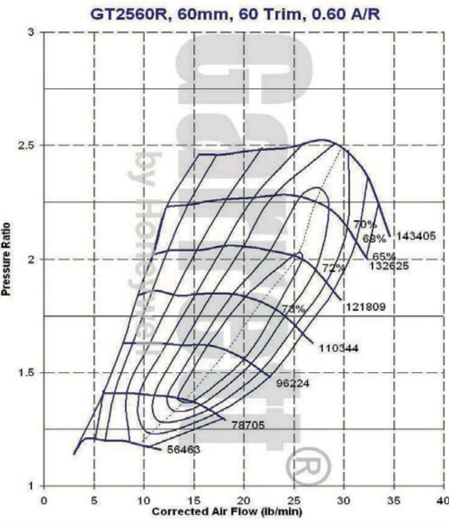
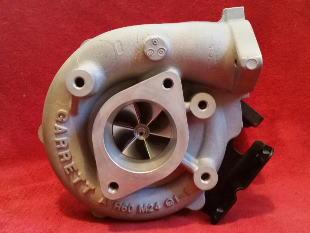
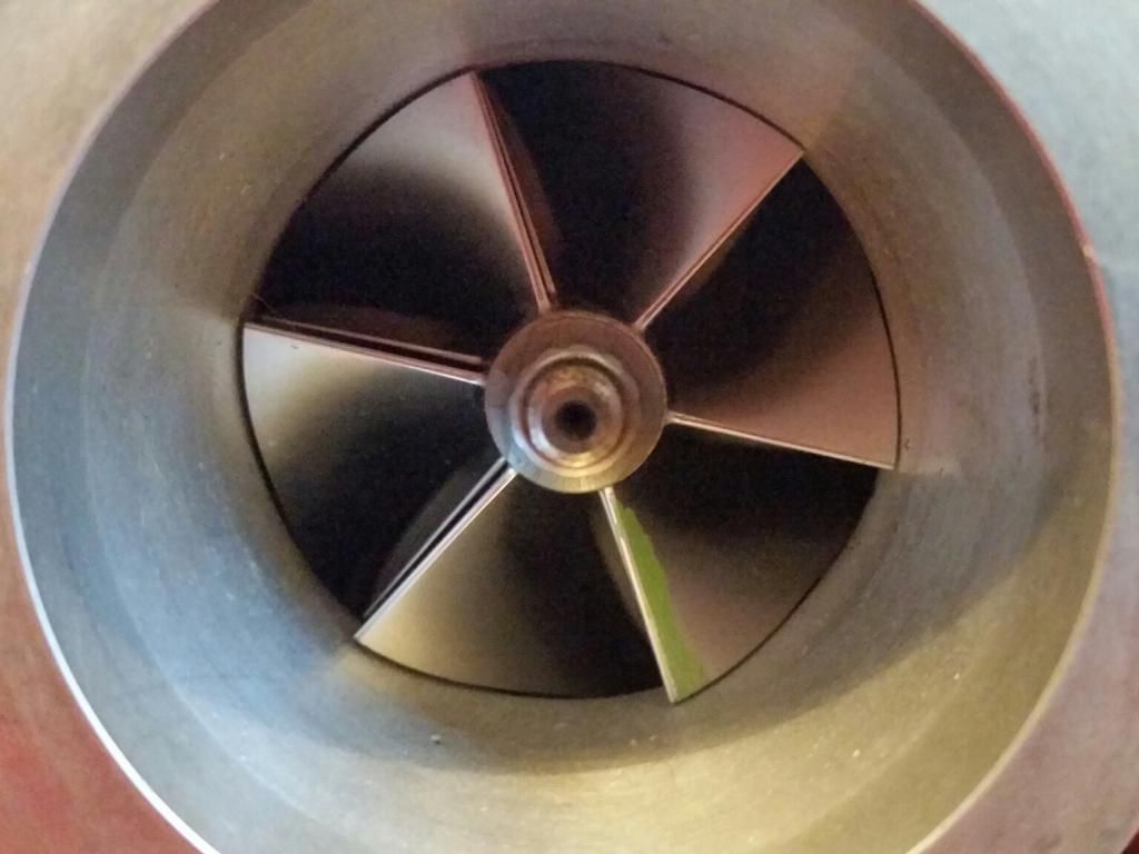
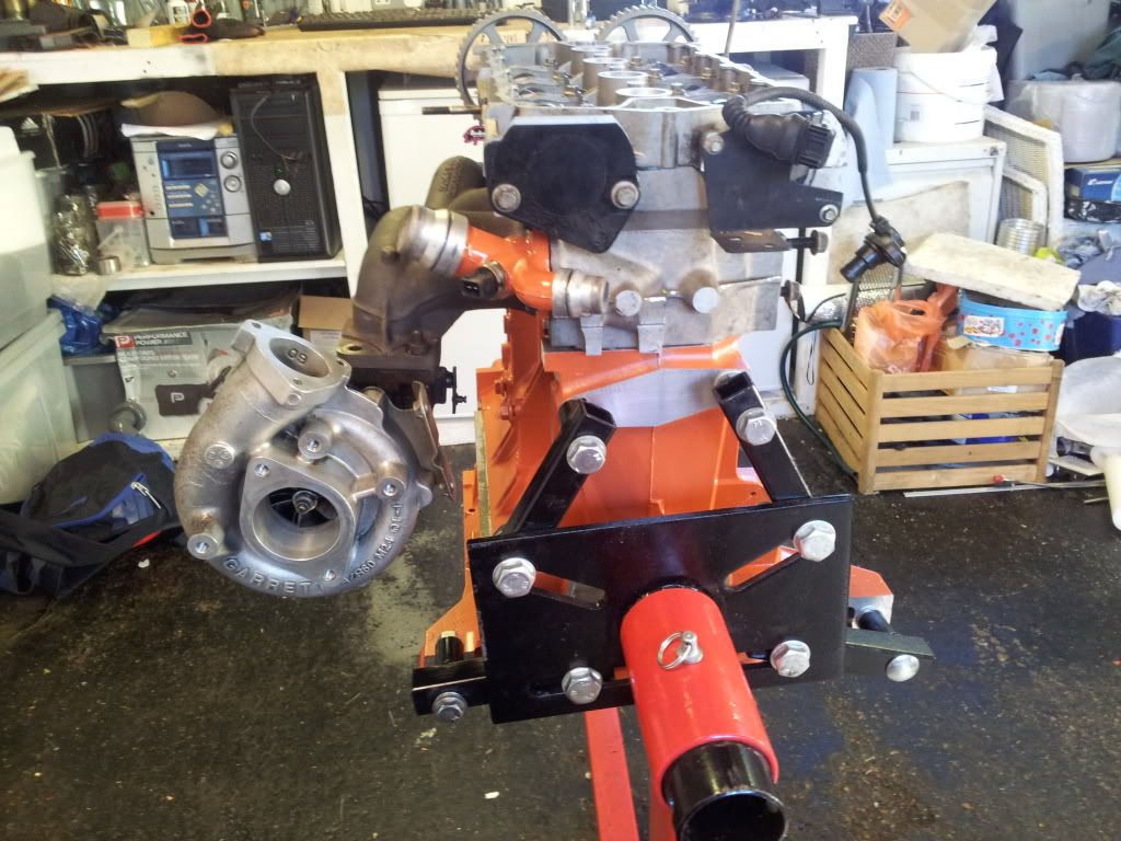
I opted for a T28 from a Nissan 200SX S15 which I know fits the stock manifold. The s15 has a ball bearing turbo and I had it rebuilt with a nice new billet compressor wheel (arguably no real improvement from a normal wheel but the blades had some nicks so was worth doing). This turbo is very similar to the GT2560R which should be perfect for my requirements. If I can get everything else right, this turbo should be good for 250bhp - 300bhp.
GT2560R
Compressor map for the GT2560R for those interested:
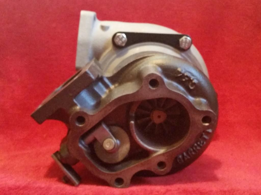
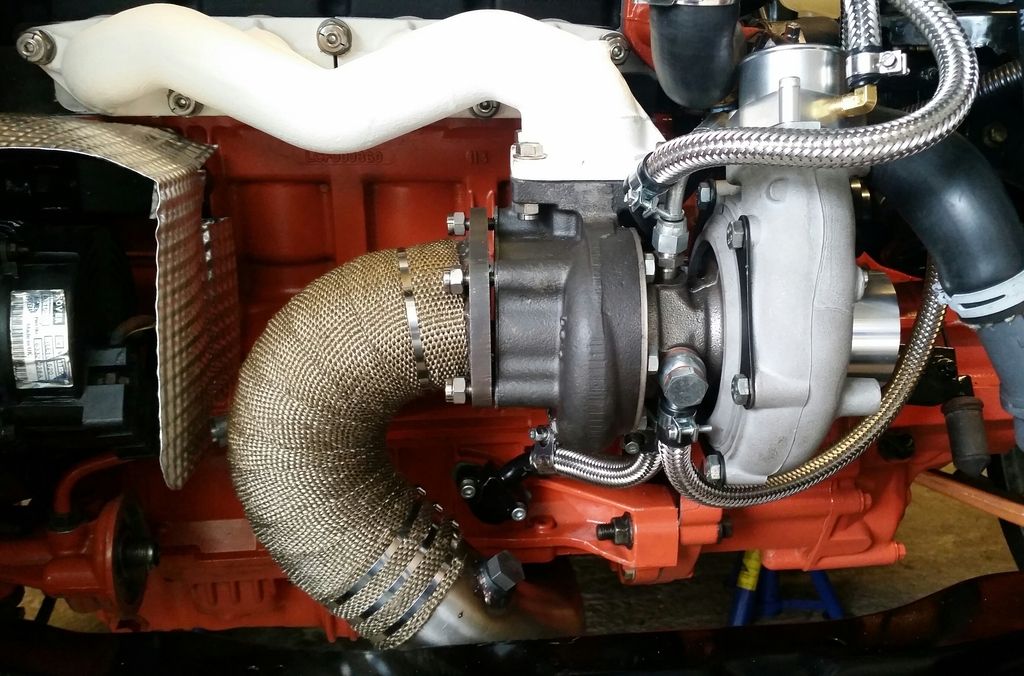
Some pics of the turbo after getting it back from refurbing:
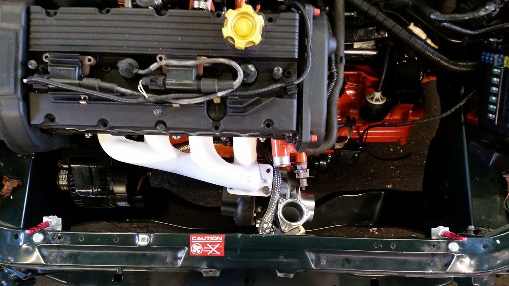
I mocked it up to see what it would look like. At this point I realised I was going to have to mount the fans on the front of the rad or possibly move the rad forward.
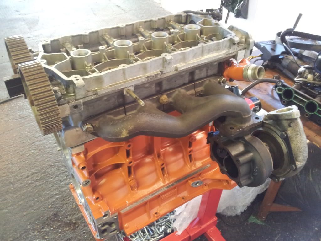
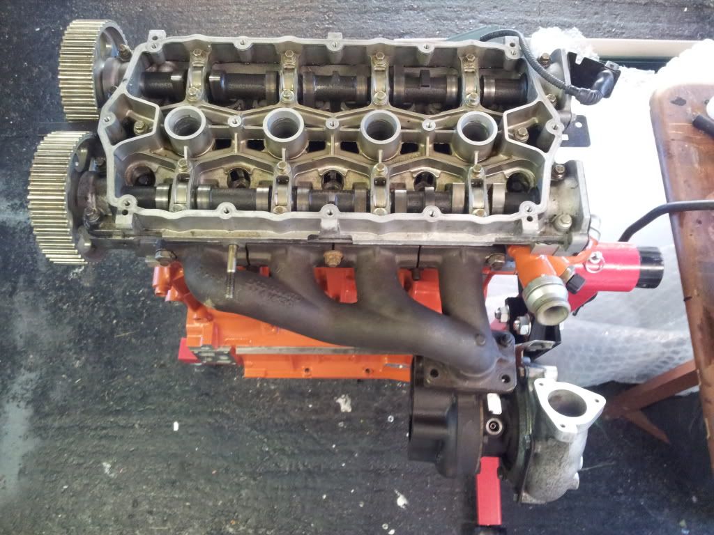
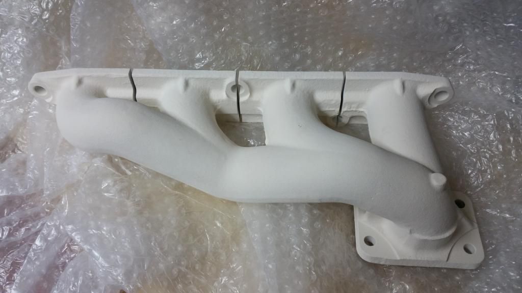
As you can see, I'm sticking with the standard log manifold. It's actually not that bad. It will be port matched with the head and given a good fettle inside to improve flow.
And ceramic coated by zircotec to help keep engine bay temps down:
The standard unit on the k-turbo is a gt2052. Not terribly efficient and runs out of puff at 220bhp-ish by which point it's blowing a lot of hot air.
I opted for a T28 from a Nissan 200SX S15 which I know fits the stock manifold. The s15 has a ball bearing turbo and I had it rebuilt with a nice new billet compressor wheel (arguably no real improvement from a normal wheel but the blades had some nicks so was worth doing). This turbo is very similar to the GT2560R which should be perfect for my requirements. If I can get everything else right, this turbo should be good for 250bhp - 300bhp.
GT2560R
Compressor map for the GT2560R for those interested:
Some pics of the turbo after getting it back from refurbing:
I mocked it up to see what it would look like. At this point I realised I was going to have to mount the fans on the front of the rad or possibly move the rad forward.
As you can see, I'm sticking with the standard log manifold. It's actually not that bad. It will be port matched with the head and given a good fettle inside to improve flow.
And ceramic coated by zircotec to help keep engine bay temps down:
Edited by Stuballs on Wednesday 4th October 14:08
Thanks guys. 
Yeah not many on the road anymore and value is slowly increasing as a result. I think I got mine when the market was at its lowest and there were over 400 still taxed then. Problem is that almost any collision will write one off. And those that don't go out to accidents get eaten by rust!
Yeah not many on the road anymore and value is slowly increasing as a result. I think I got mine when the market was at its lowest and there were over 400 still taxed then. Problem is that almost any collision will write one off. And those that don't go out to accidents get eaten by rust!
Head!
Cylinder head, that is. The original plan was to keep the Variable Valve Timing to see how it coped with forced induction. The VVC only works on the inlet and varies the duration from 220 degrees to 295 degrees as rpm increases. It does this by slowing the cam down as the lobe opens the valve. It's a clever but fragile system. They are always loud and most VVCs sound a little bit diesel! That said, it works and they are a hoot to drive.
My turbo is probably too restrictive for the big overlap the VVC produces at full duty, but since I can control it with the Emerald ECU I figured I could just keep it at low duration if it caused problems. The intention was to tune it for optimum results. It didn't quite work out and I went in a different direction in the end. More on that later. For now, I'll share what I did anyway.
I had a nightmare finding a good VVC head that hadn't been skimmed to hell and back. Unfortunately a lot of VVC engines have had hgf which led to overheating and a softening of the head. This causes the liners to indent the head so I was looking for one without those telltale sunken areas around the fire rings.
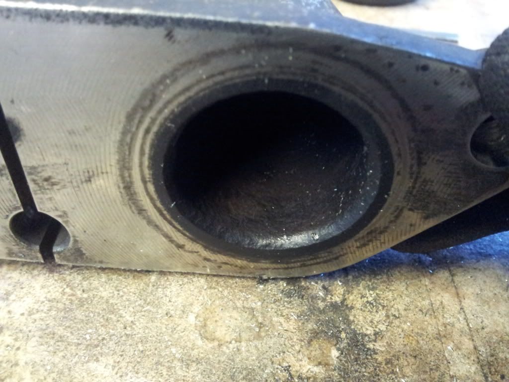
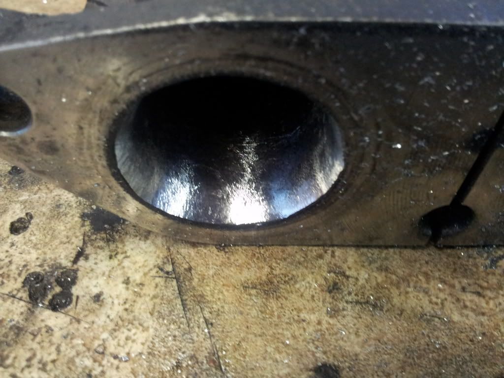
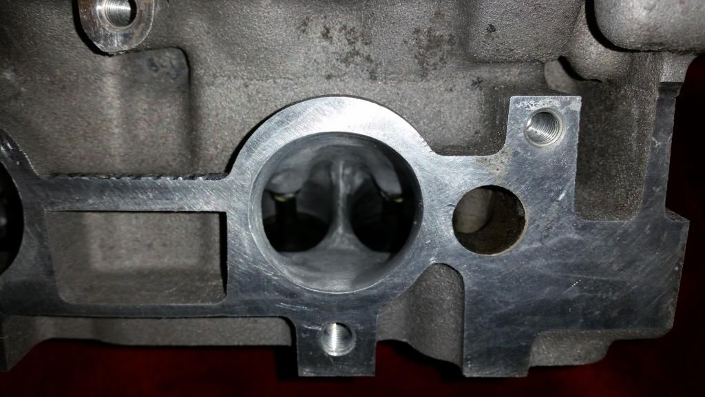
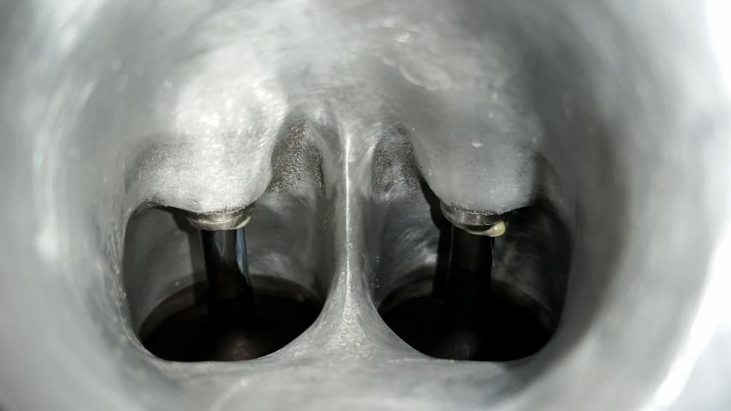
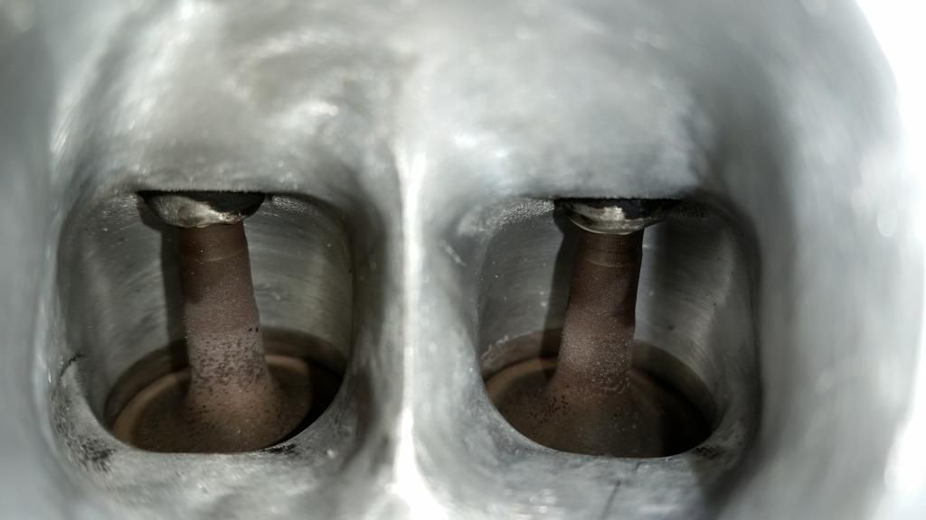
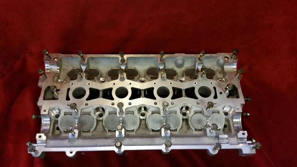
The head I ended up using was from a Caterham. It was basically good and had only ever had a light skim. I dropped it off for a quick porting with TDR motorsport by Brands Hatch who I know through the BRM forum. They opened everything up for improved flow and matched the ports to inlet and exhaust manifolds. You'll see a fair bit of meat was left on the valve guide bosses to help heat dissipation.
Before:
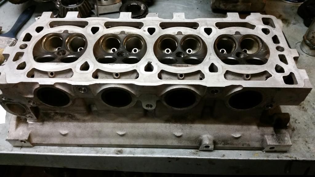
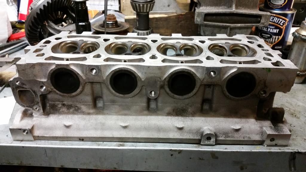
After:
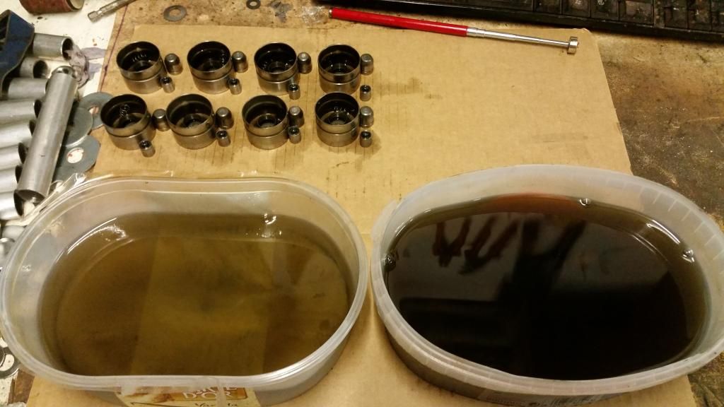
I then turned my attention to the lifters. They weren't too bad but the cam-lobe surfaces had some scuffs so I planished them with various grades of wet and dry.
Cleaning:
Planishing:
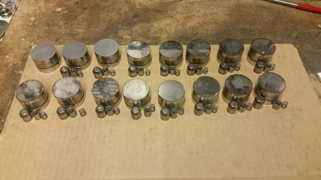
All in!
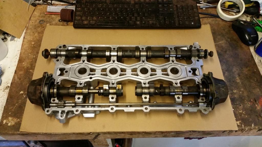
Now to the VVC mechs. I had thought to simply transfer the VVC gear from one cam ladder into the other. Unfortunately they needed synching. An hour of reading later and I had it sussed - whilst daunting, it's actually not that difficult and you just have to be patient and careful not to let the mechanisms fall apart while you're handling them! If that happens you're in a world of pain and there are dozens of parts.
I elected to use the SAIC developed so-called "n-series" head gasket. This was quite literally marketed by x-part as the ultimate fix for k-series head gaskets and is comprised of the SAIC developed gasket, grade 10.9 head bolts (with a slightly revised tightening procedure) and the stiffer oil rail.
Many layers:
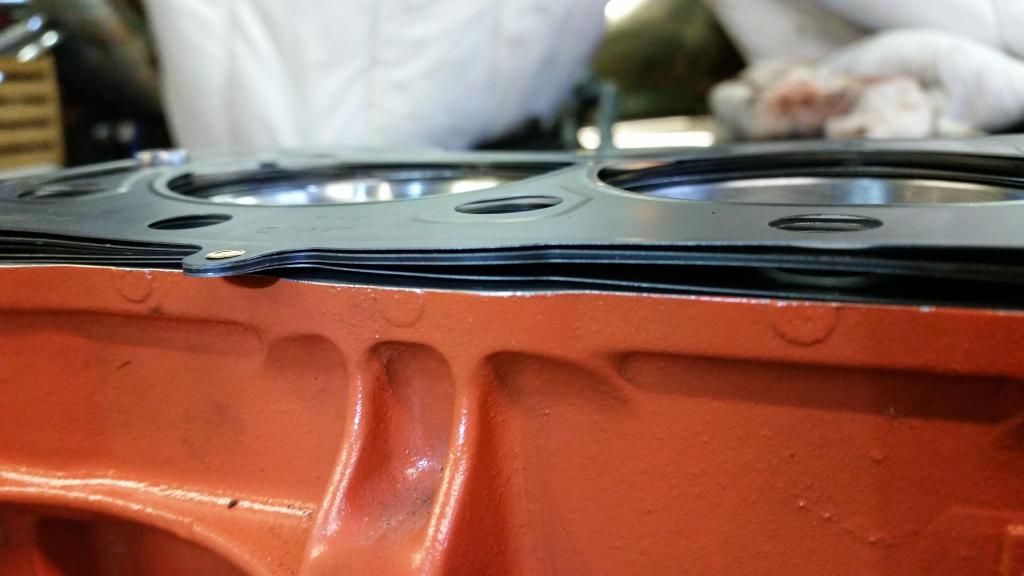
Head on!!
The gasket compressed to 2mm with the head torqued down. I re-measured the volume of the combustion chamber post porting and skim and I should now have a static compression ratio of almost exactly 9:1. which is what I wanted.
Also took care of a few other bits
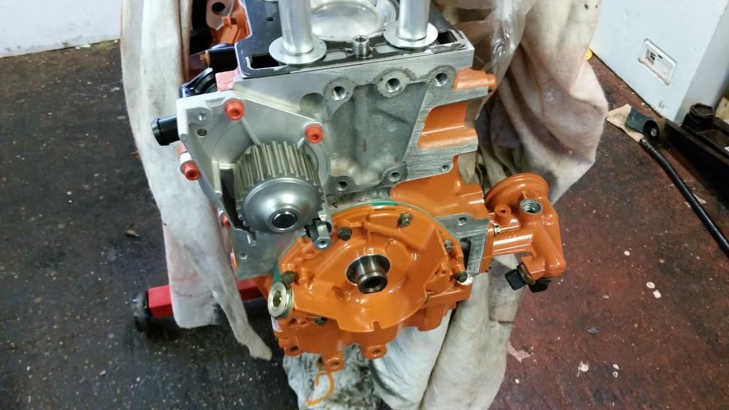
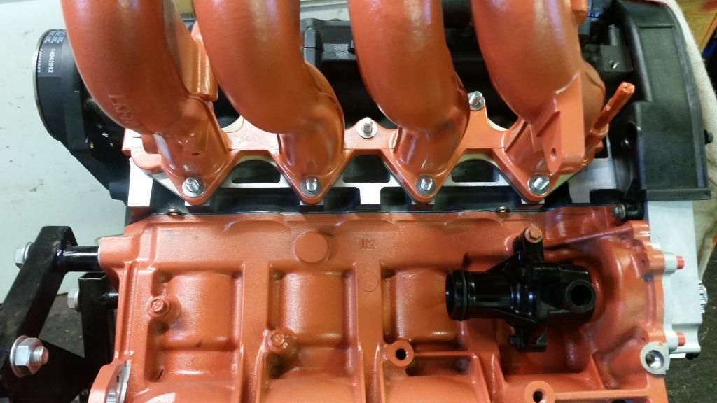
Oil pump modified with radius'd edges for improved flow and fitted. I actually did this to the old one then decided to just replace it with new. So had to do it all again (only better - of course!). Naturally, I painted it orange! Also fitted water pump. I am as-yet undecided on the orange bolts - you'll not see these ones anyway but I have a whole engine bay kit - If they look gash I'll use normal stainless.
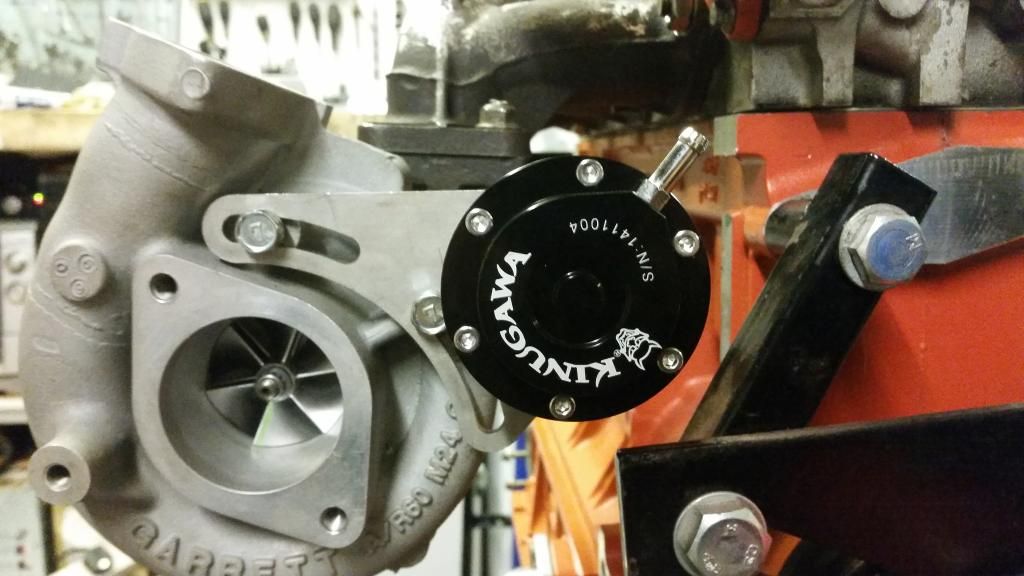
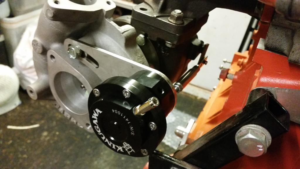
Test fitted Kinugawa Actuator to the turbo - I'm using this because the turbo didn't come with an actuator and this came with a handy adjustable bracket and various combinations of rod. It's from Japan and is a lovely piece of kit which certainly looks well made. They supplied it fitted with a 0.5 bar (7 psi) spring but I also have a 0.8 bar (11.6psi) spring if I need it. I'll be running an electronic boost controller so will decide later which spring I actually use. I'm very impressed
Cylinder head, that is. The original plan was to keep the Variable Valve Timing to see how it coped with forced induction. The VVC only works on the inlet and varies the duration from 220 degrees to 295 degrees as rpm increases. It does this by slowing the cam down as the lobe opens the valve. It's a clever but fragile system. They are always loud and most VVCs sound a little bit diesel! That said, it works and they are a hoot to drive.
My turbo is probably too restrictive for the big overlap the VVC produces at full duty, but since I can control it with the Emerald ECU I figured I could just keep it at low duration if it caused problems. The intention was to tune it for optimum results. It didn't quite work out and I went in a different direction in the end. More on that later. For now, I'll share what I did anyway.
I had a nightmare finding a good VVC head that hadn't been skimmed to hell and back. Unfortunately a lot of VVC engines have had hgf which led to overheating and a softening of the head. This causes the liners to indent the head so I was looking for one without those telltale sunken areas around the fire rings.
The head I ended up using was from a Caterham. It was basically good and had only ever had a light skim. I dropped it off for a quick porting with TDR motorsport by Brands Hatch who I know through the BRM forum. They opened everything up for improved flow and matched the ports to inlet and exhaust manifolds. You'll see a fair bit of meat was left on the valve guide bosses to help heat dissipation.
Before:
After:
I then turned my attention to the lifters. They weren't too bad but the cam-lobe surfaces had some scuffs so I planished them with various grades of wet and dry.
Cleaning:
Planishing:
All in!
Now to the VVC mechs. I had thought to simply transfer the VVC gear from one cam ladder into the other. Unfortunately they needed synching. An hour of reading later and I had it sussed - whilst daunting, it's actually not that difficult and you just have to be patient and careful not to let the mechanisms fall apart while you're handling them! If that happens you're in a world of pain and there are dozens of parts.
I elected to use the SAIC developed so-called "n-series" head gasket. This was quite literally marketed by x-part as the ultimate fix for k-series head gaskets and is comprised of the SAIC developed gasket, grade 10.9 head bolts (with a slightly revised tightening procedure) and the stiffer oil rail.
Many layers:
Head on!!
The gasket compressed to 2mm with the head torqued down. I re-measured the volume of the combustion chamber post porting and skim and I should now have a static compression ratio of almost exactly 9:1. which is what I wanted.
Also took care of a few other bits
Oil pump modified with radius'd edges for improved flow and fitted. I actually did this to the old one then decided to just replace it with new. So had to do it all again (only better - of course!). Naturally, I painted it orange! Also fitted water pump. I am as-yet undecided on the orange bolts - you'll not see these ones anyway but I have a whole engine bay kit - If they look gash I'll use normal stainless.
Test fitted Kinugawa Actuator to the turbo - I'm using this because the turbo didn't come with an actuator and this came with a handy adjustable bracket and various combinations of rod. It's from Japan and is a lovely piece of kit which certainly looks well made. They supplied it fitted with a 0.5 bar (7 psi) spring but I also have a 0.8 bar (11.6psi) spring if I need it. I'll be running an electronic boost controller so will decide later which spring I actually use. I'm very impressed
Edited by Stuballs on Wednesday 4th October 14:11
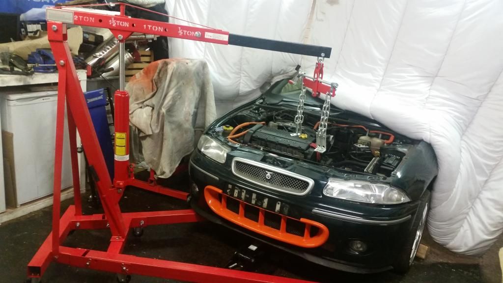
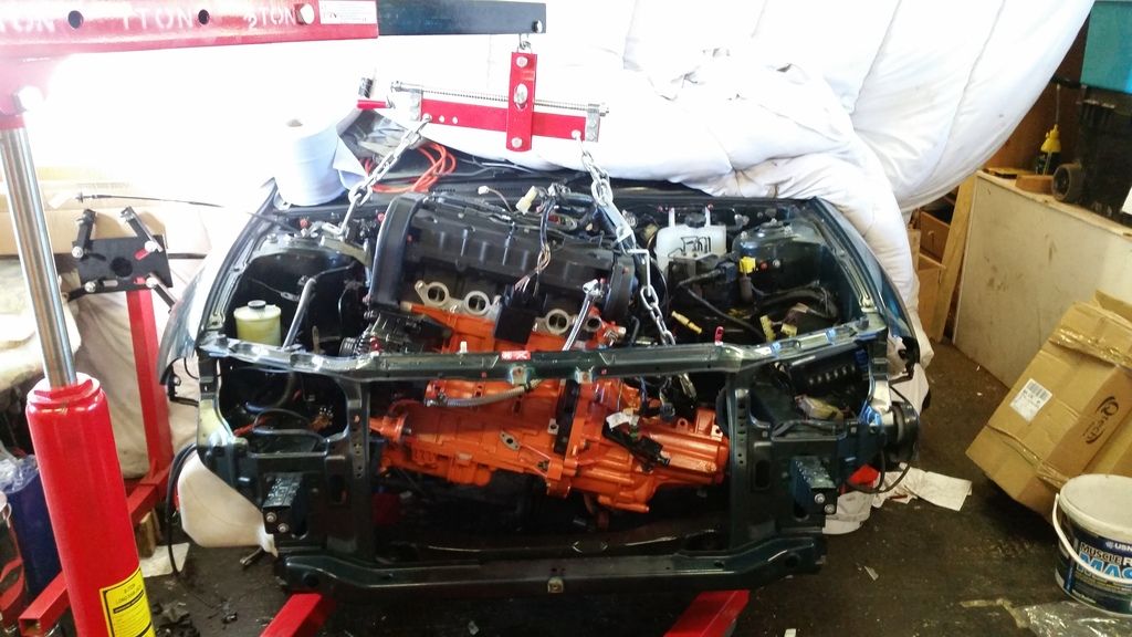
So I'd gone about as far as I could with the engine without needing donor bits from the engine in the BRM. So time to whip out the old leaky lump! Decided just to buy an engine crane rather than hire. No time pressure then and I can just sell it when I'm done with it. For an Ebay cheapy it's a great bit of kit.
Front bumper off
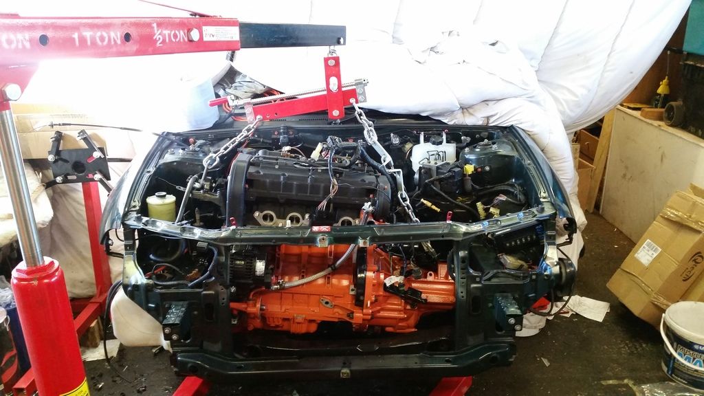
Let the lifting commence!
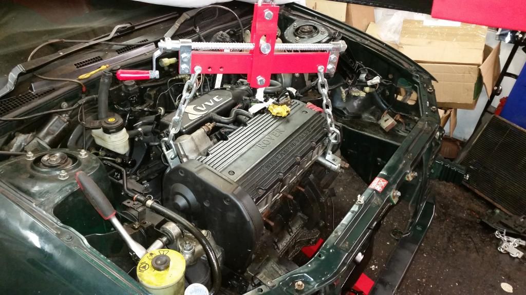
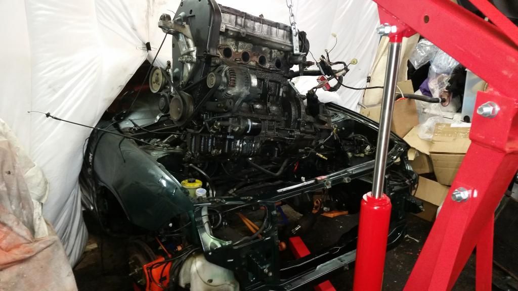
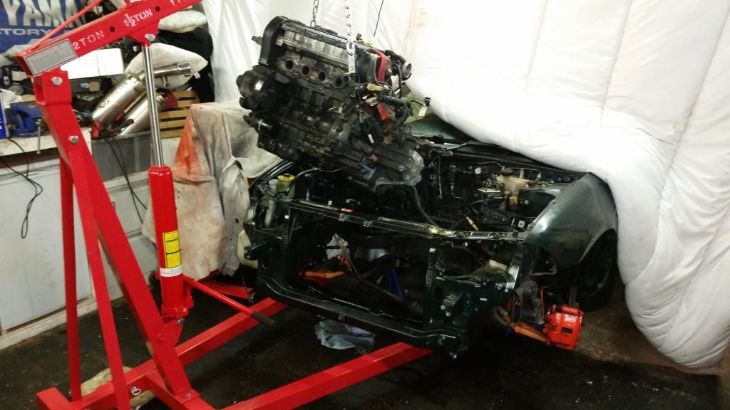
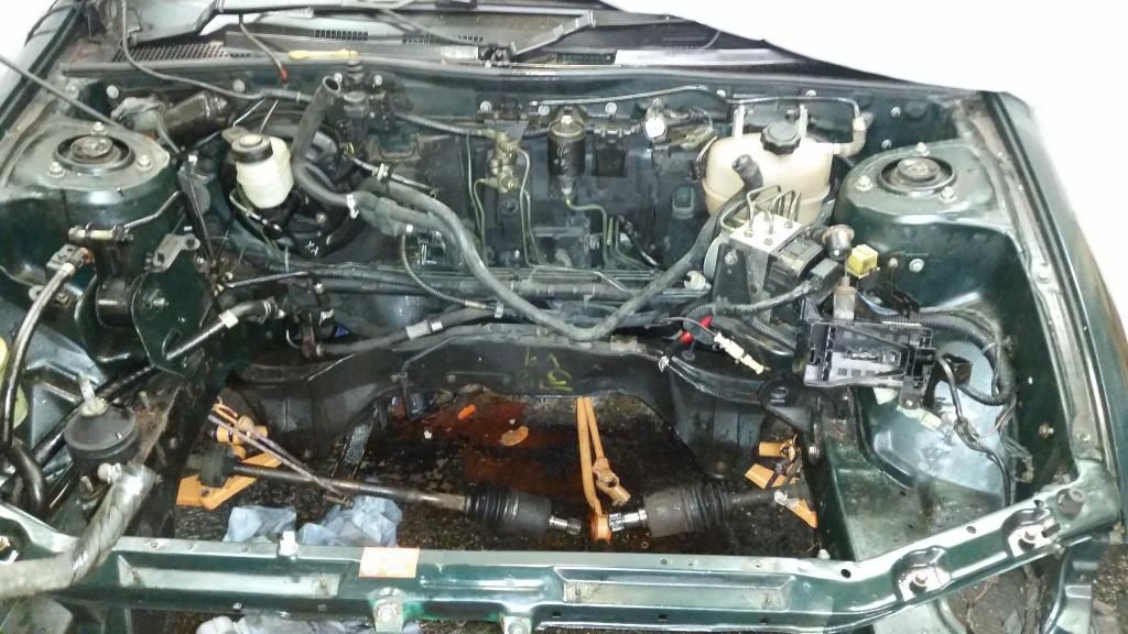
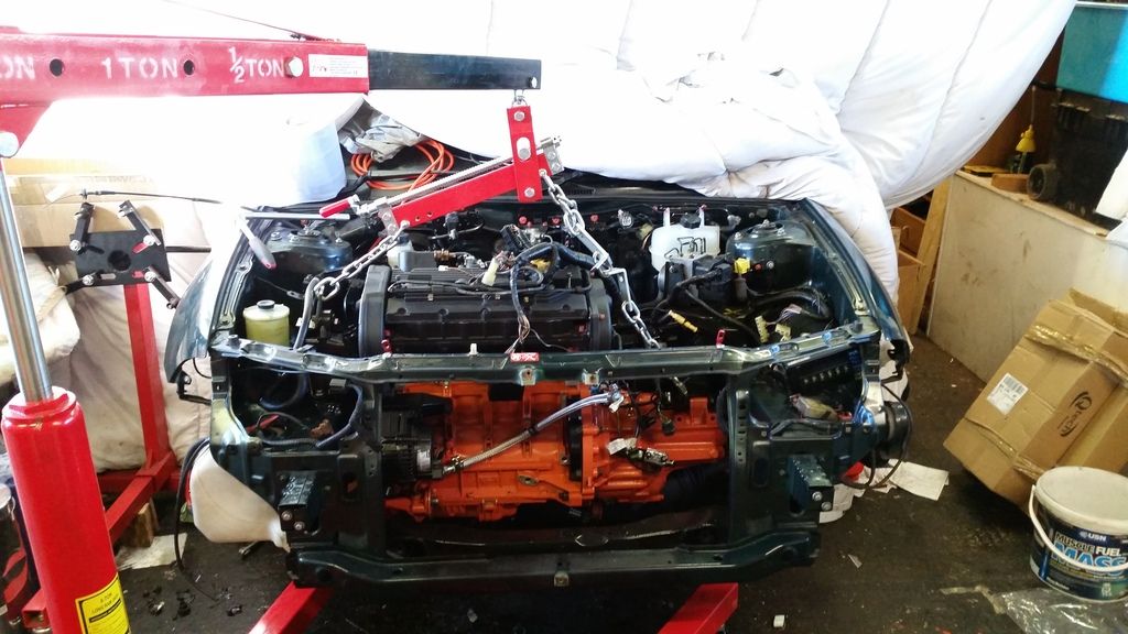
She's free! And my god in such an awful state. Imagine an engine put together with no gaskets and this is the level of oil leak.
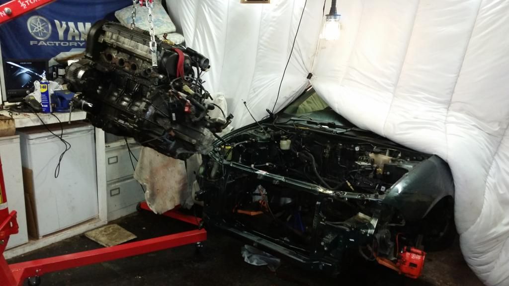
We'll just set this to the side for later...
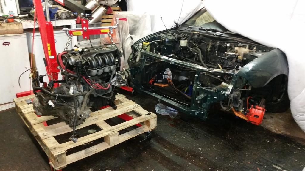
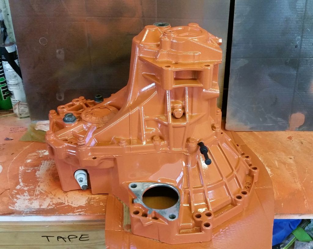
Got the gearbox off and cleaned up a bit as I'll be needing that later...
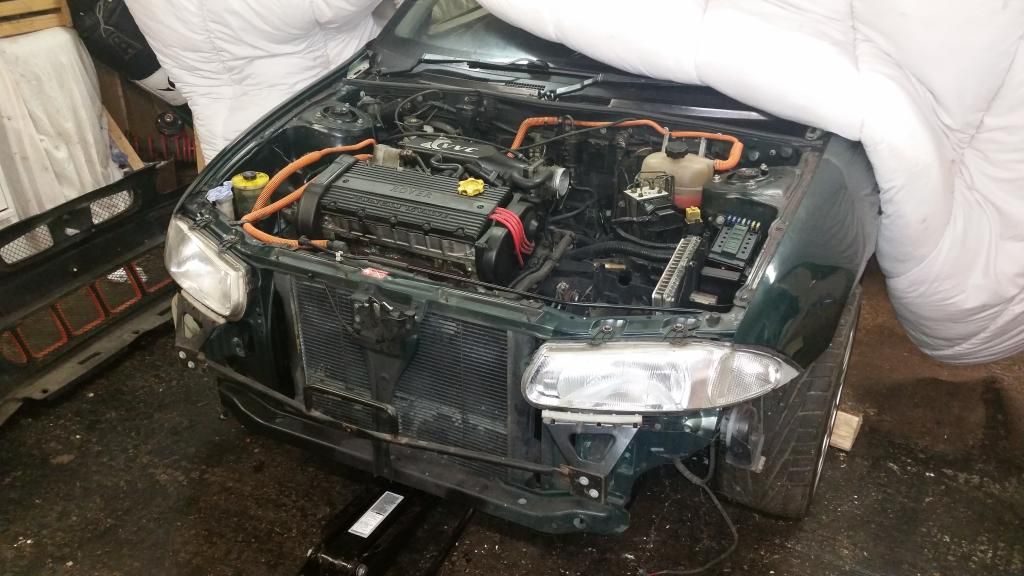
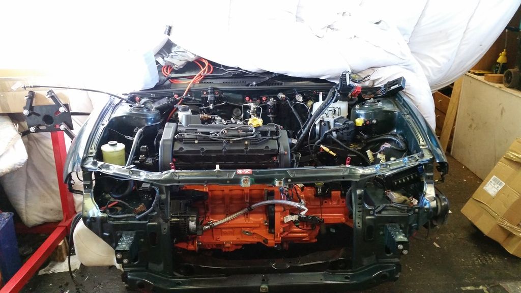
Engine bay doesn't look too bad in this pic but in the flesh it was very grubby. Sound proofing disintegrating and everything just covered in a film of grease.
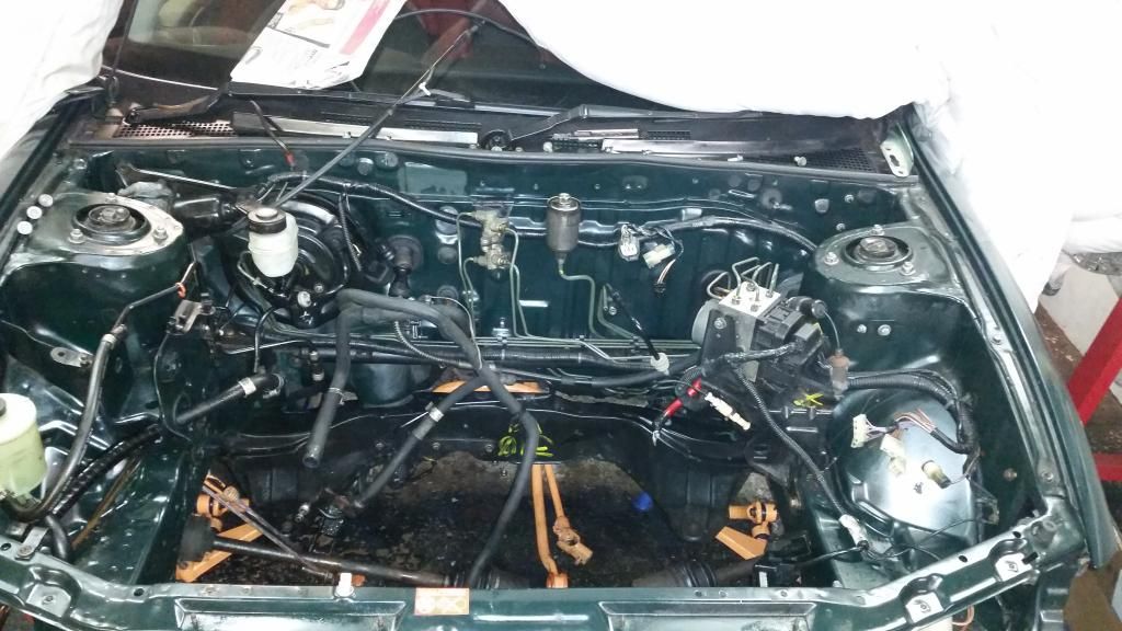
Several hours' and a few cans of silicone spray later:
I removed all the brackets to clean them properly and apply a lick of paint. Trying out this orange bolt kit I got. Not sure yet. will see how it looks once all together. Managed to clean the expansion bottle out with plenty of washing powder and a handful of pea shingle shaken like a maniac. Came up as new!
There then followed a long period of prepping, priming and painting various brackets and engine mounts. I've become somewhat obsessed with the black and orange!
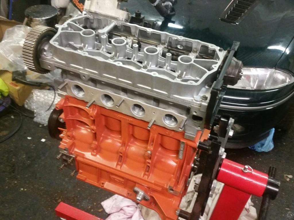
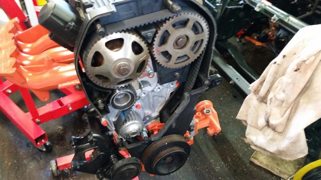
Stripping the old engine down gave me access to bits I need for the new engine, which included the cambelt rear cover. So fitted the cambelt.
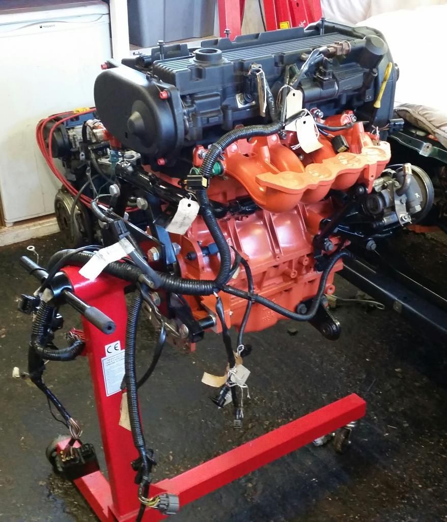
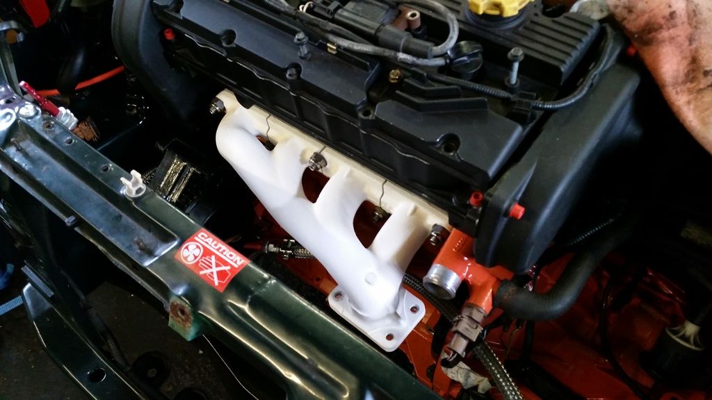
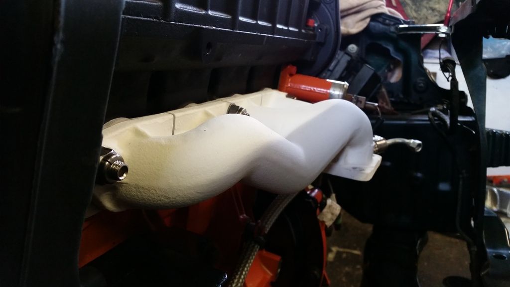
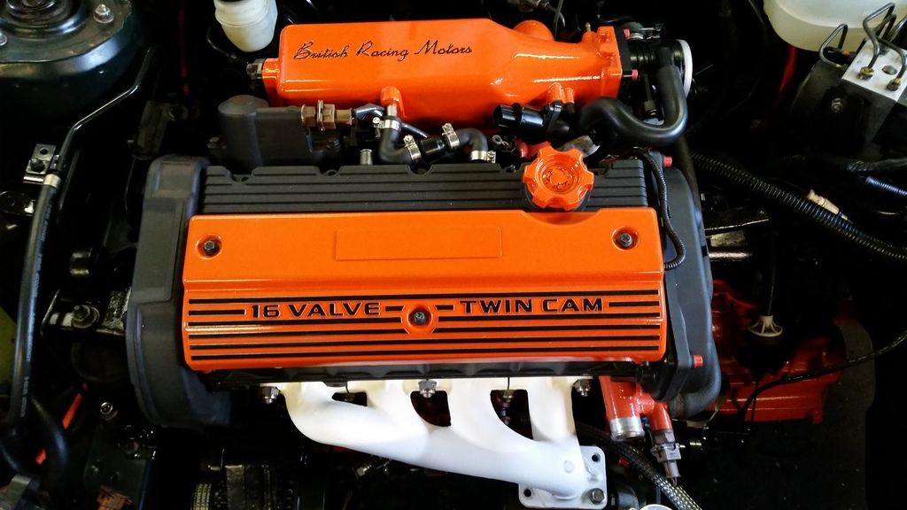
Getting the engine built back up with ancillaries and more orange bolts (still not sure...) and the orange inlet manifold. Note the special Ferriday thermal gasket to keet the temperature of the inlet runners down. this, unfortunately, did not match my matched ports so require very, very careful fettling to match all three up.
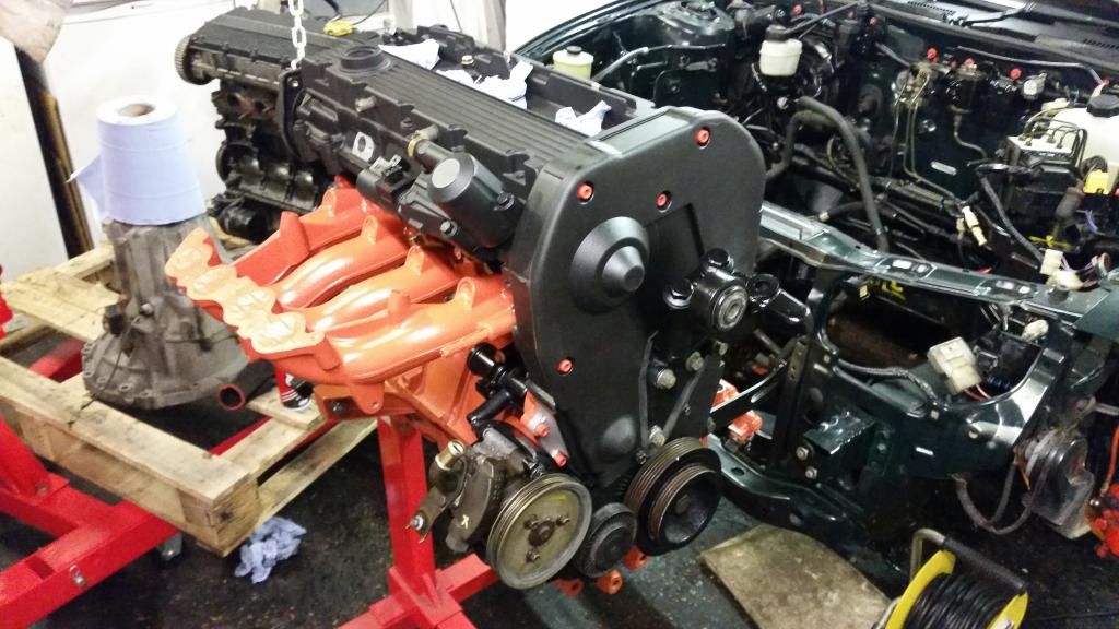
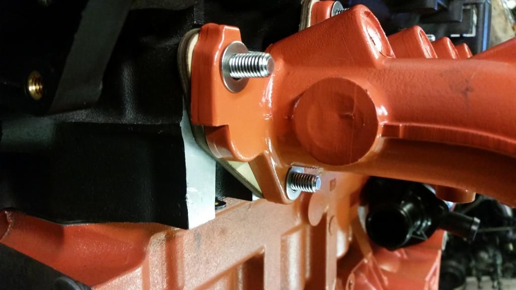
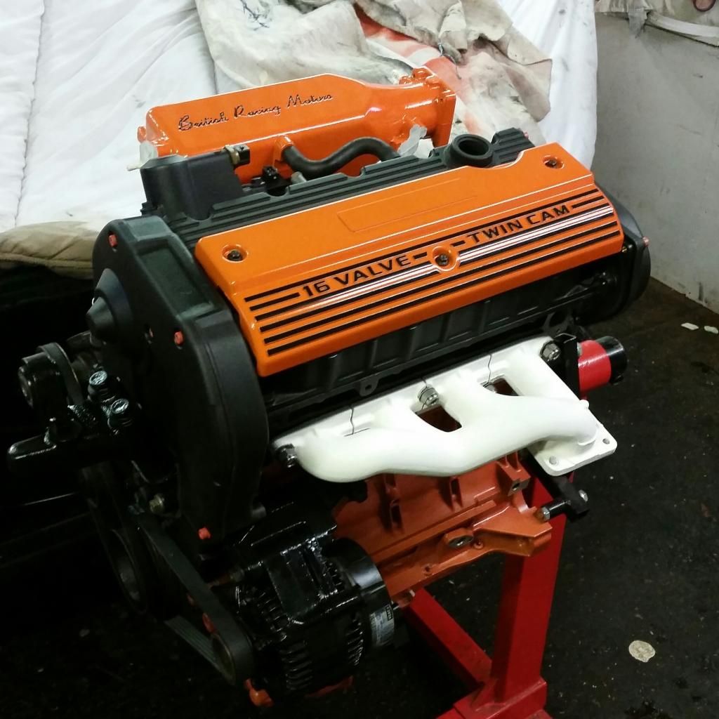
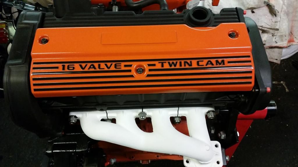
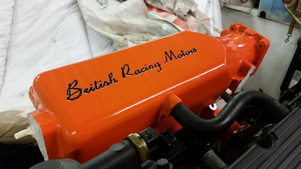
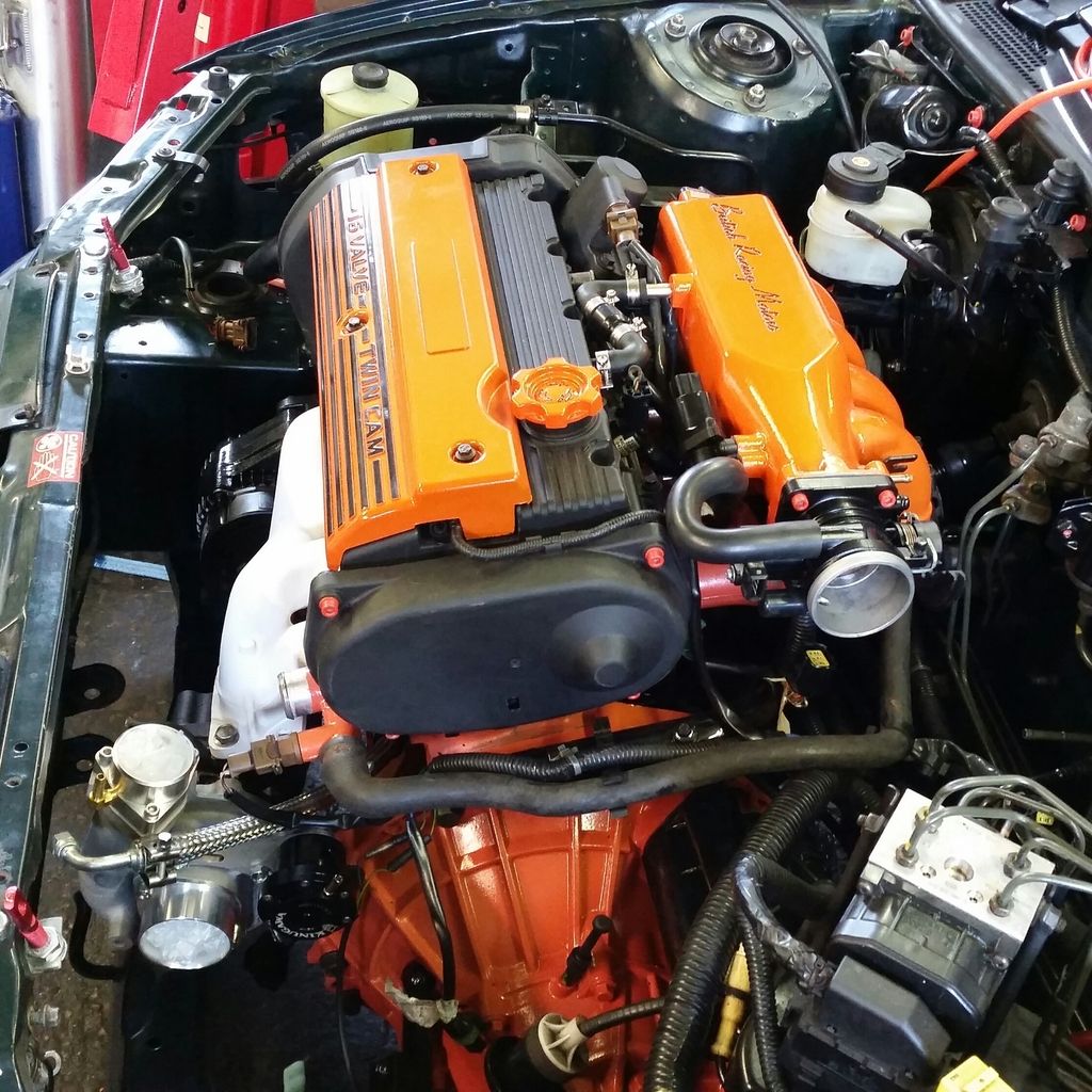
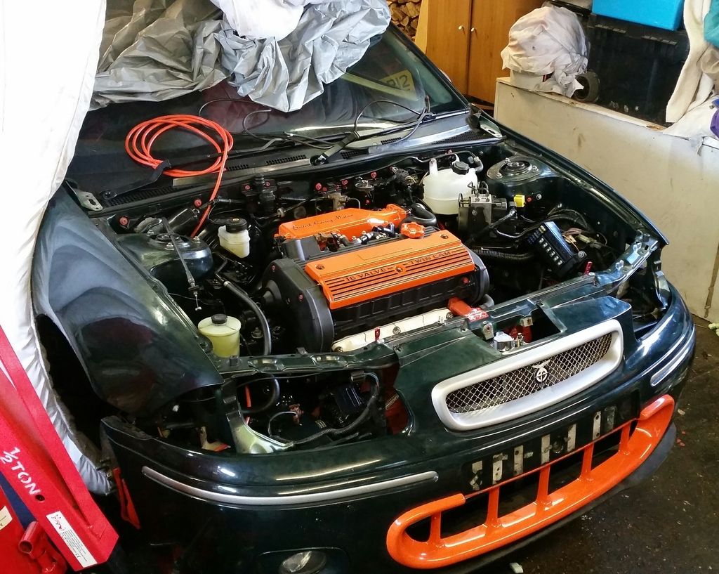
Then I thought I'd better mock up THE bling orange bits just to get an idea of how they'll look. Of course this required getting the ceramic manifold out again for maximum effect. The inlet plenum is a one-off mod a fellow BRM owner had done years ago. Standard just has the embossed "VVC".
Then sorted the engine loom - sticking with the BRM loom so had to sort wiring for the coils which are now plug-top. Love a bit of soldering.
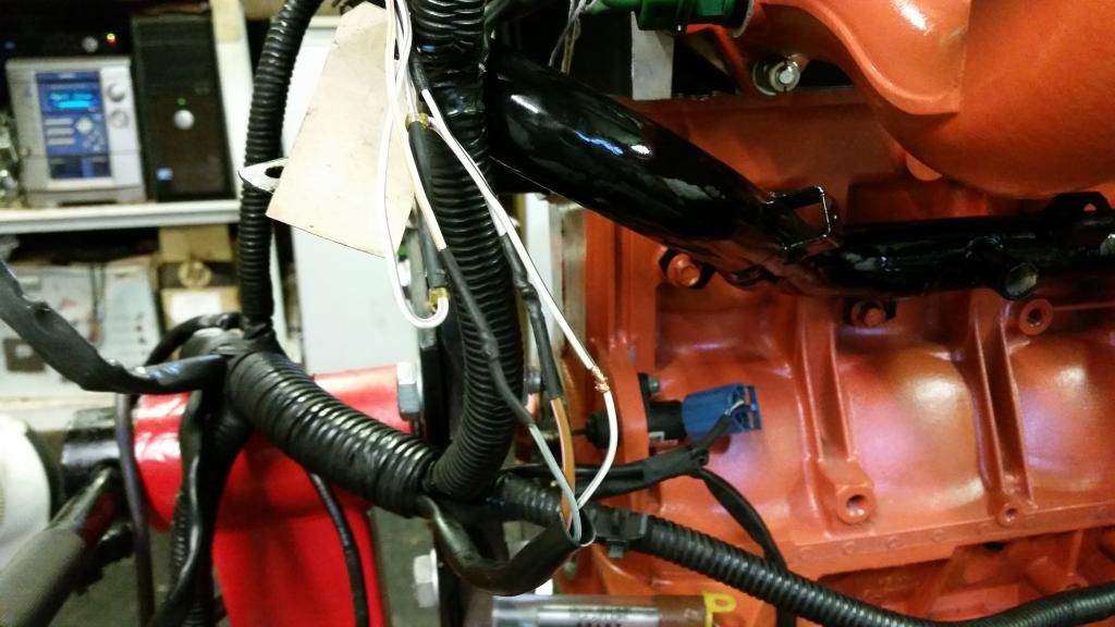
Loom is on and labelled everything!
Pretty much ready to go in now...
Front bumper off
Let the lifting commence!
She's free! And my god in such an awful state. Imagine an engine put together with no gaskets and this is the level of oil leak.
We'll just set this to the side for later...
Got the gearbox off and cleaned up a bit as I'll be needing that later...
Engine bay doesn't look too bad in this pic but in the flesh it was very grubby. Sound proofing disintegrating and everything just covered in a film of grease.
Several hours' and a few cans of silicone spray later:
I removed all the brackets to clean them properly and apply a lick of paint. Trying out this orange bolt kit I got. Not sure yet. will see how it looks once all together. Managed to clean the expansion bottle out with plenty of washing powder and a handful of pea shingle shaken like a maniac. Came up as new!
There then followed a long period of prepping, priming and painting various brackets and engine mounts. I've become somewhat obsessed with the black and orange!
Stripping the old engine down gave me access to bits I need for the new engine, which included the cambelt rear cover. So fitted the cambelt.
Getting the engine built back up with ancillaries and more orange bolts (still not sure...) and the orange inlet manifold. Note the special Ferriday thermal gasket to keet the temperature of the inlet runners down. this, unfortunately, did not match my matched ports so require very, very careful fettling to match all three up.
Then I thought I'd better mock up THE bling orange bits just to get an idea of how they'll look. Of course this required getting the ceramic manifold out again for maximum effect. The inlet plenum is a one-off mod a fellow BRM owner had done years ago. Standard just has the embossed "VVC".
Then sorted the engine loom - sticking with the BRM loom so had to sort wiring for the coils which are now plug-top. Love a bit of soldering.
Loom is on and labelled everything!
Pretty much ready to go in now...
Edited by Stuballs on Wednesday 3rd January 13:10
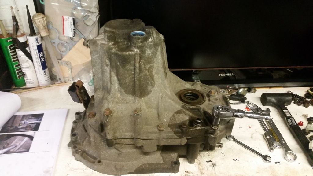
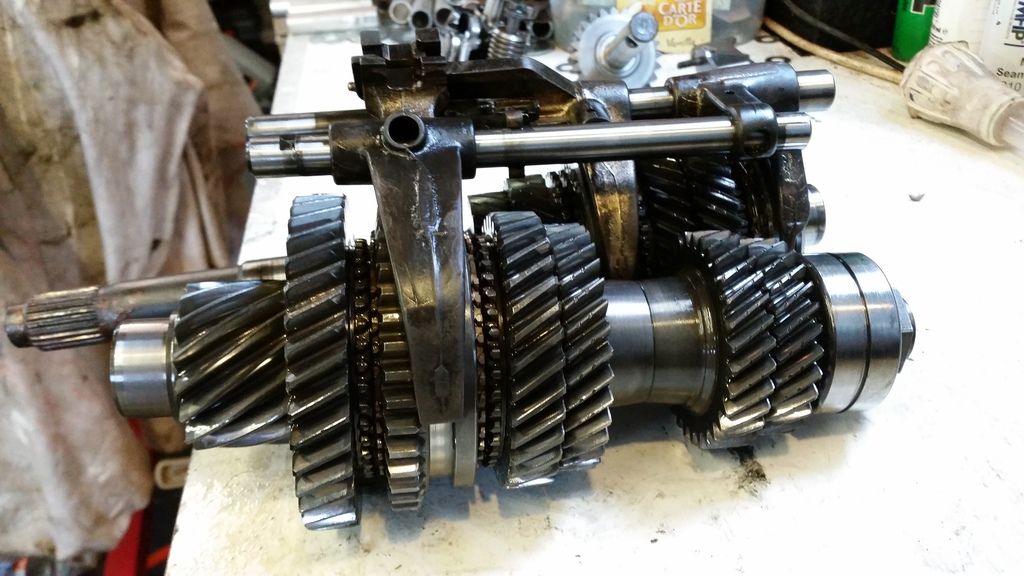
Time to get the engine in, but first to upgrade the gearbox :
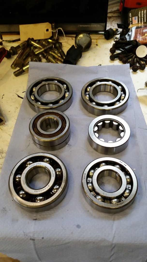
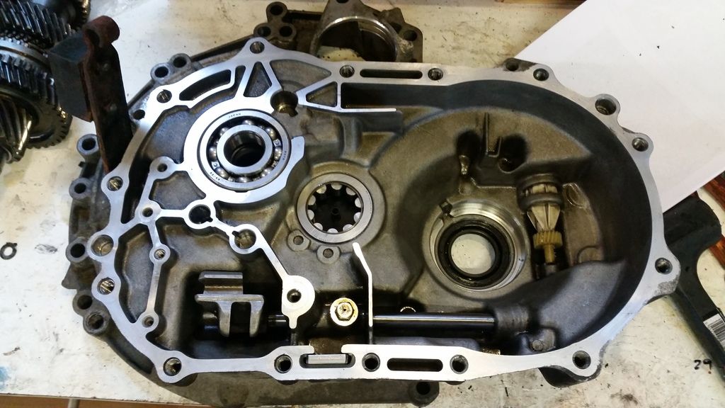
Nothing too fancy - just upgrading the bearings to steel caged items in place of the chocolate versions rover used in the pg-1. I'm using the BRM box that comes with Type B Torsen limited slip diff.
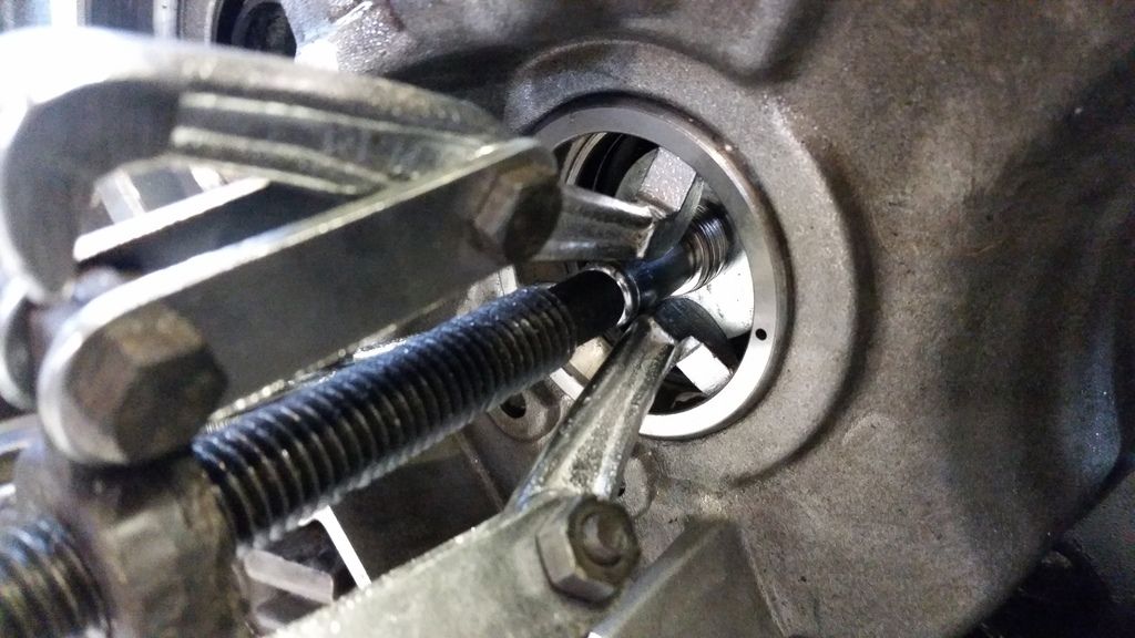
started by stripping the 'box down
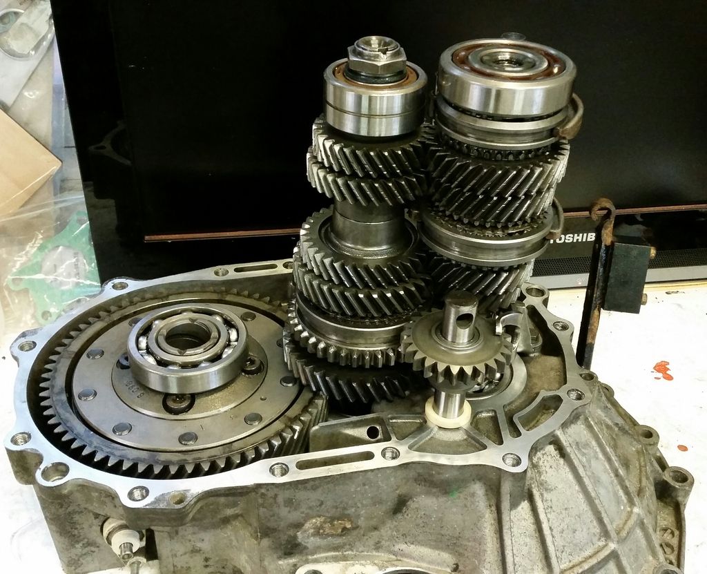
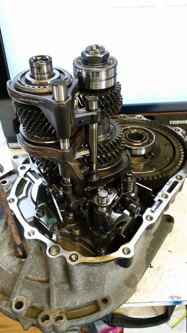
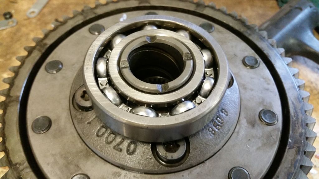
new bearings ready to go:
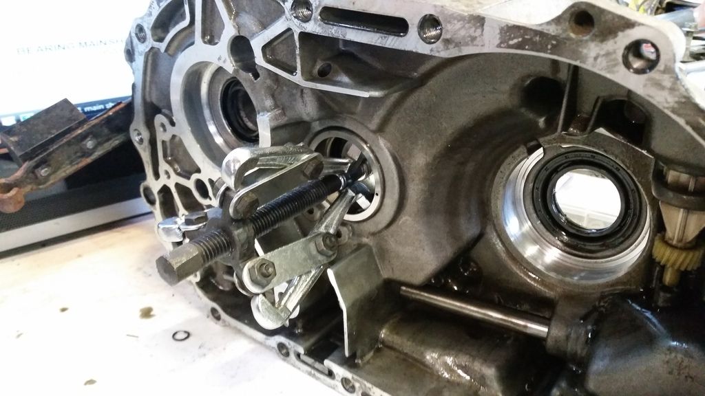
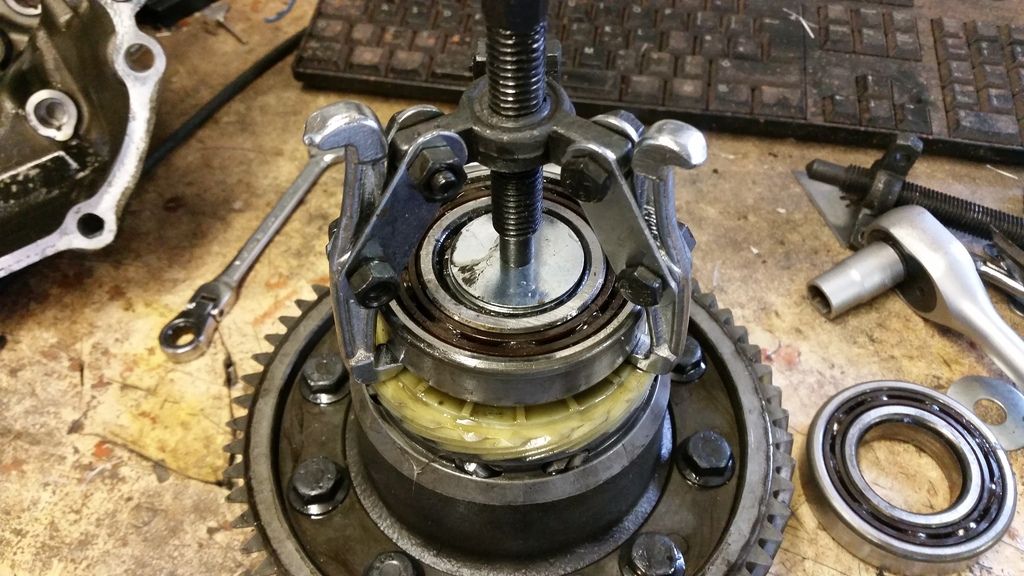
Getting the bearings out is easy with careful use of heat and bearing pullers
Painted to match the engine
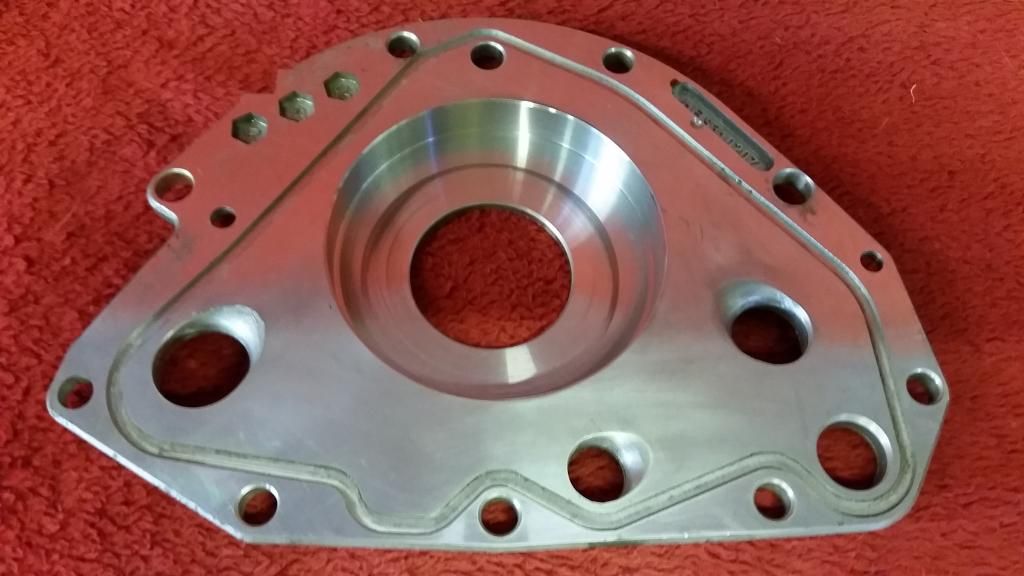
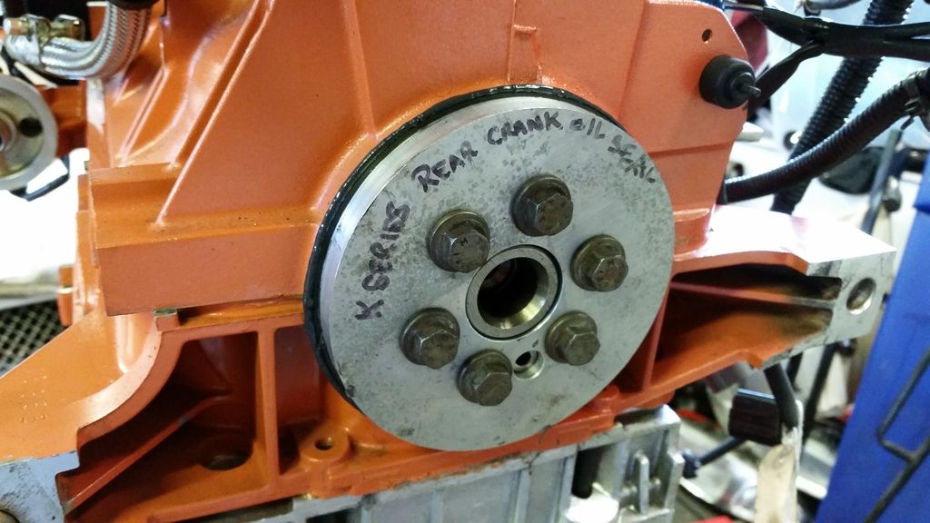
Fitting the rear crank oil seal in using a homemade tool borrowed from a buddy.
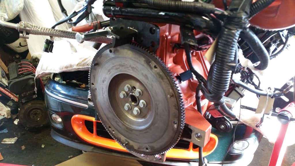
Flywheel on with new bolts of course. This is a Freelander 2 flywheel which allows me to use the slightly larger 220 turbo clutch, but still has k-series fitment. I elected not to go for a lightened crank as everyone else seems to do. I was talked into this by Vibration Free who did my balancing. I slightly regret the decision but this will make for an easier to drive car. Obviously I can always fit a lighter unit later down the road if I feel the need.
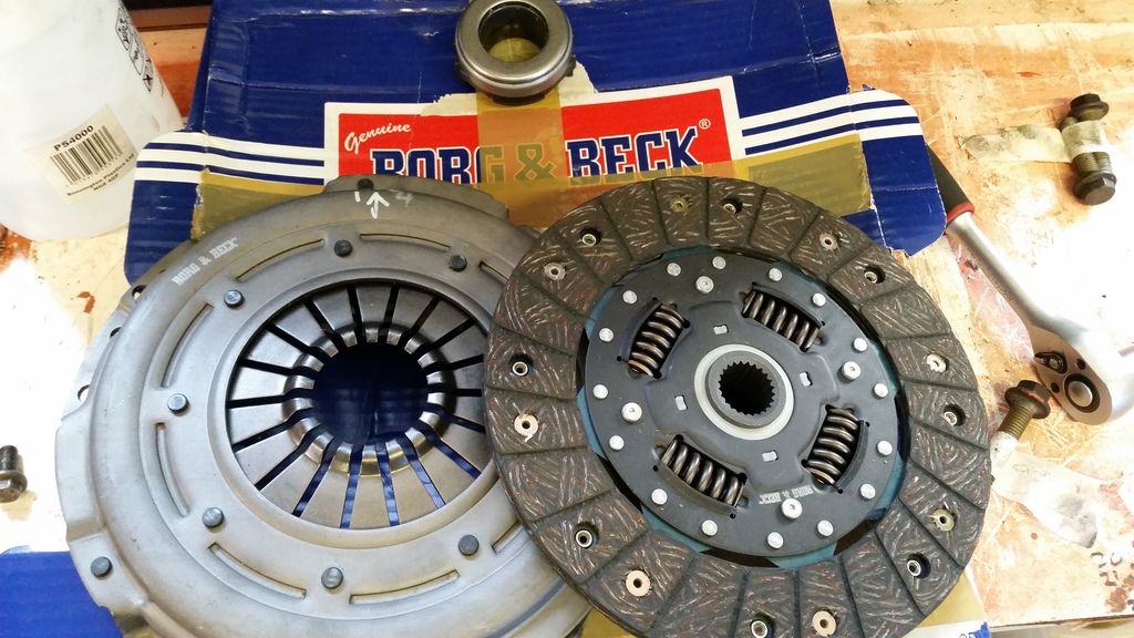
Here's my clutch - Shouldn't be aggressive at all and pedal is nice and easy. Let's see if it can cope with the torque I make. Clutch cover was balanced with the flywheel and everything else that moves in the bottom end.
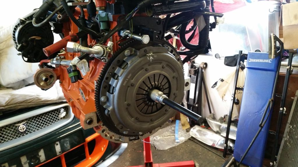
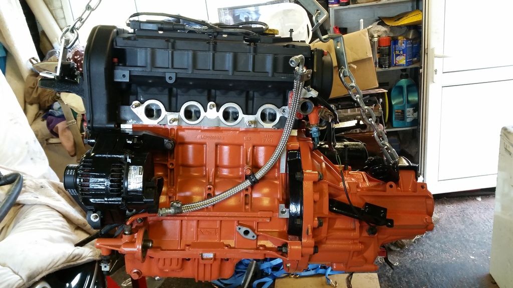
Gearbox on!
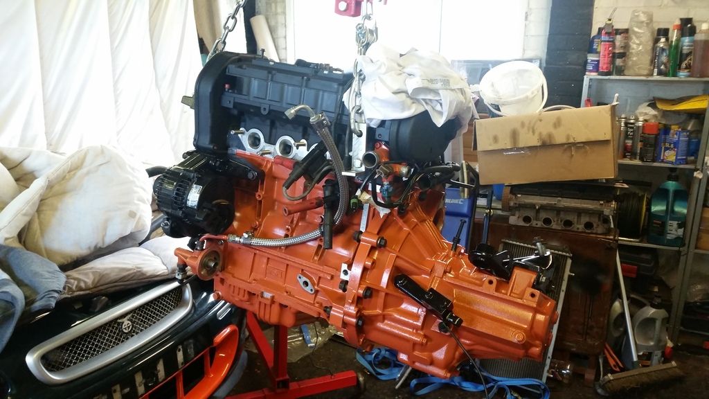
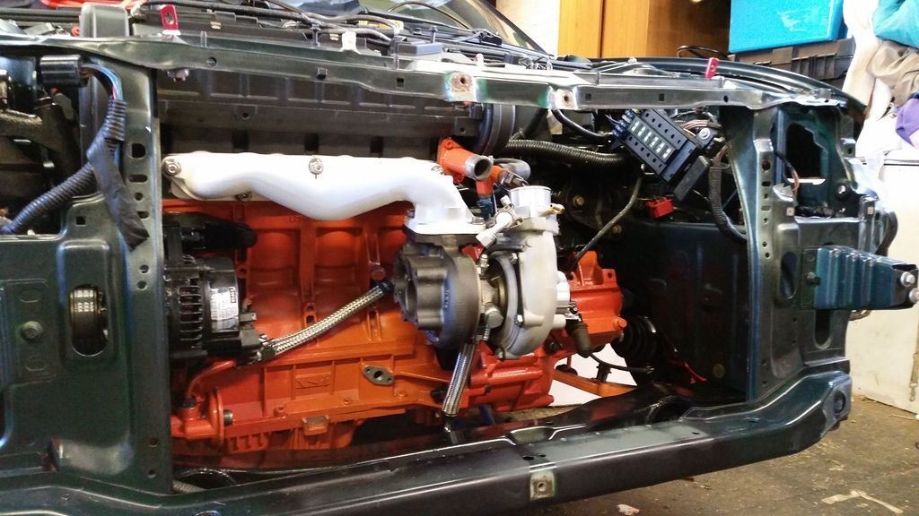
Now the really exciting bit.

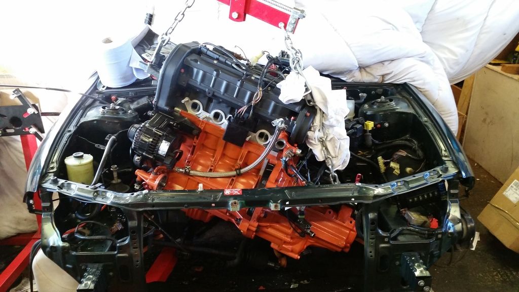
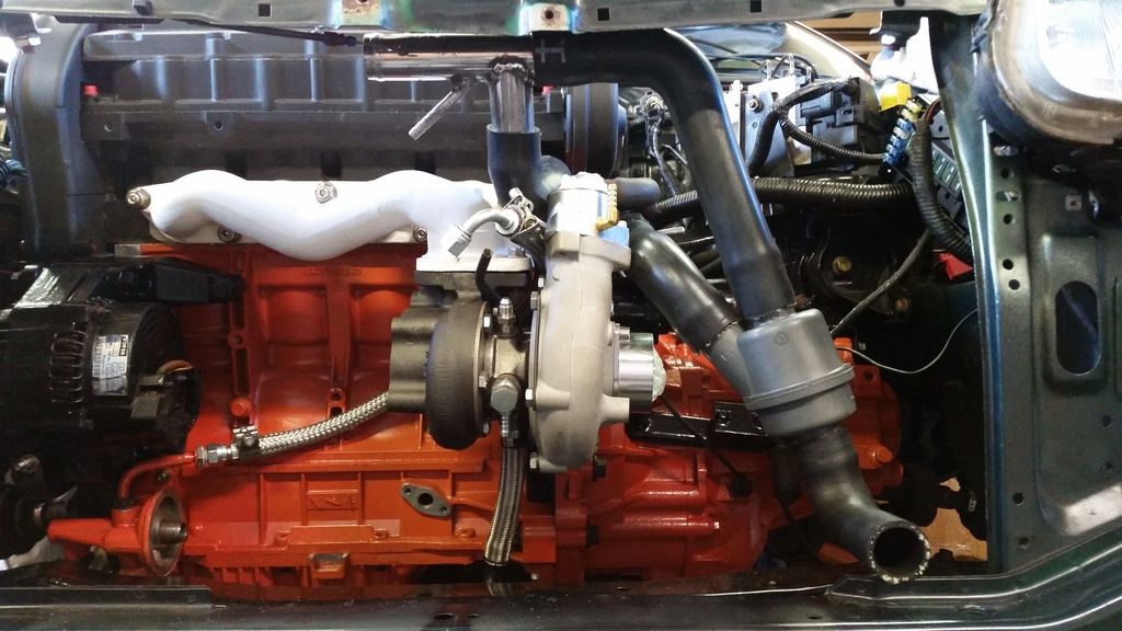
IN!!!!!
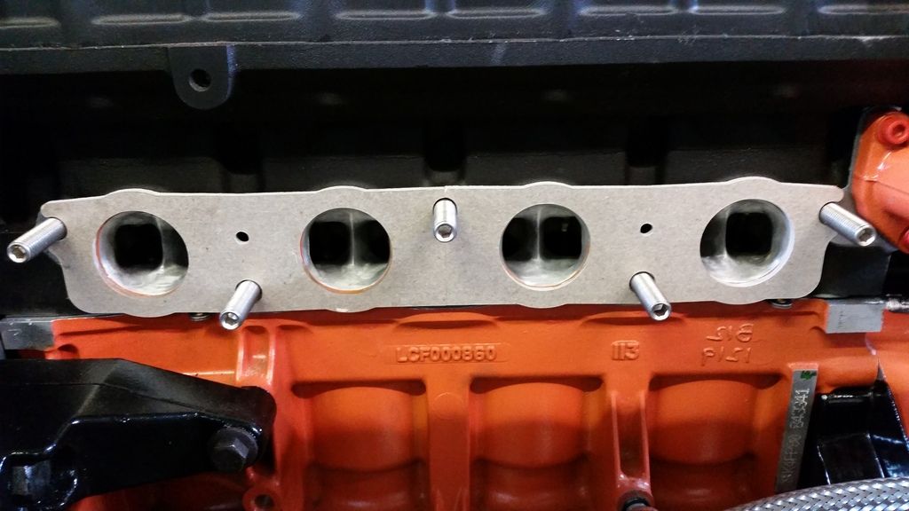
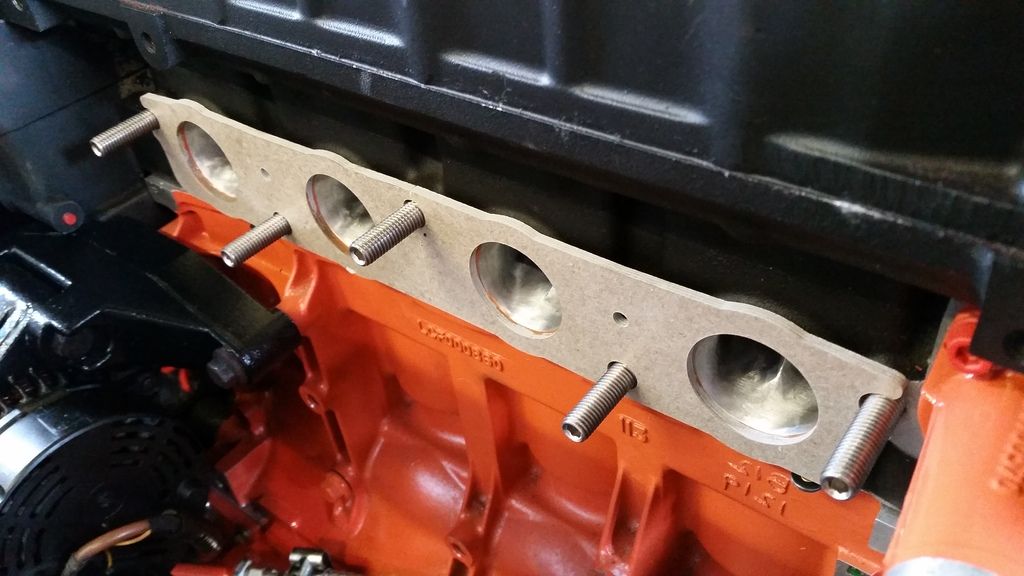
Now to get the manifold on. I'm using a Ferriday thermal gasket that reduces heat transfer back into the head (very good idea for k-series). It needs a bit of help sealing so on goes a bit of high temp gasket. (Look at those ports!)
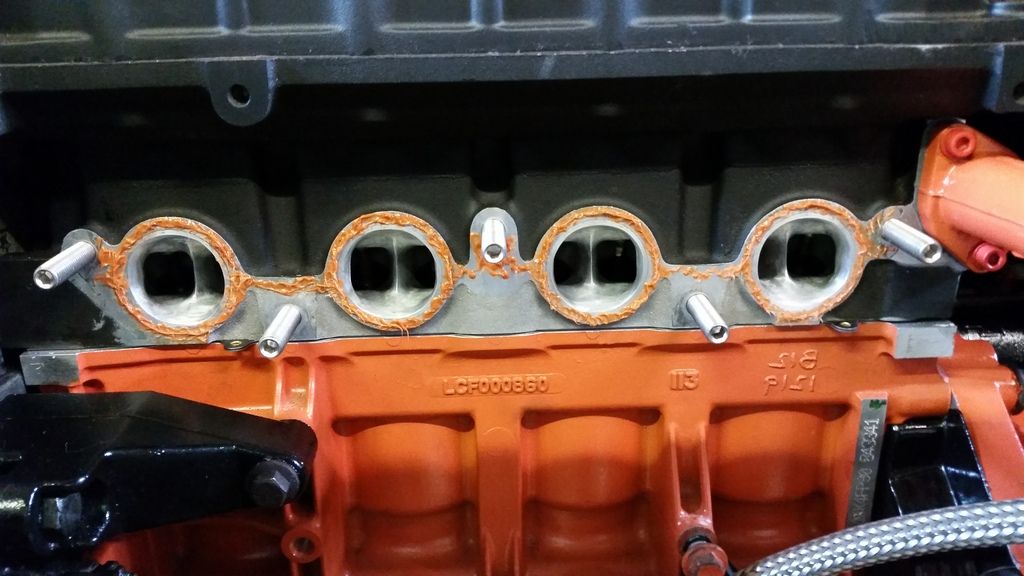
Thermal gasket in place - ports match up quite well luckily!
Zircotec ceramic coated manifold on:
And the turbo (T28r from a 200SX - rebuilt with a billet wheel and fitted with a Kinugawa actuator from Japan).
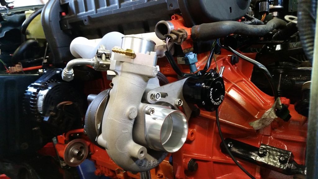
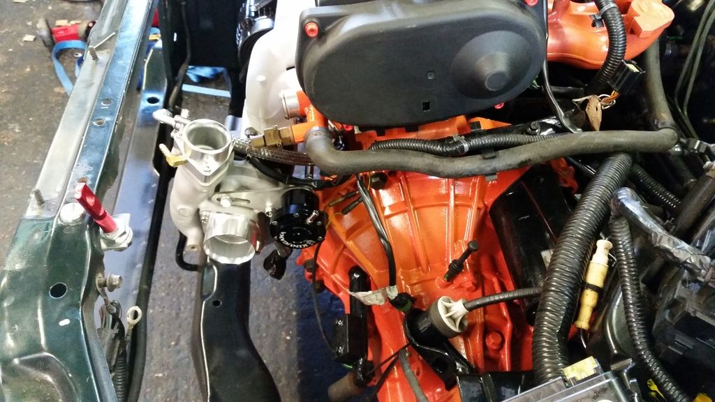
Test fitting a few bits.
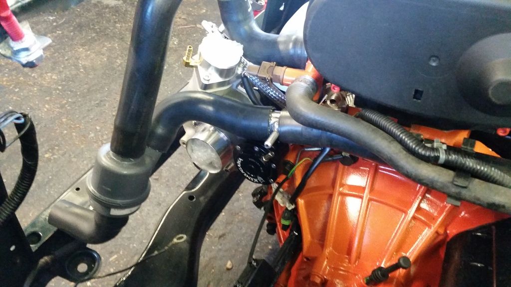
Then fitting the pressure relief thermostat (prt). This replaces the regular thermostat that would normally sit behind the block right at the pump inlet. It reduces thermal shock caused by cold coolant rushing into the hot block when the thermostat opens and it opens add rpm rises, not must tempetature. This is designed for a freelander so had to really chop and swap around the pipes to fit but this should work really well. I'm fairly confident I've got it right! Still have the plumb in the turbo feed and drain. The tee from the pipe going to the pump will feed it cold water and the tee in the top hose will take the hot water away.
Next job is to send her off for a full turbo - back stainless exhaust system...
Nothing too fancy - just upgrading the bearings to steel caged items in place of the chocolate versions rover used in the pg-1. I'm using the BRM box that comes with Type B Torsen limited slip diff.
started by stripping the 'box down


new bearings ready to go:

Getting the bearings out is easy with careful use of heat and bearing pullers


Painted to match the engine

Fitting the rear crank oil seal in using a homemade tool borrowed from a buddy.
Flywheel on with new bolts of course. This is a Freelander 2 flywheel which allows me to use the slightly larger 220 turbo clutch, but still has k-series fitment. I elected not to go for a lightened crank as everyone else seems to do. I was talked into this by Vibration Free who did my balancing. I slightly regret the decision but this will make for an easier to drive car. Obviously I can always fit a lighter unit later down the road if I feel the need.
Here's my clutch - Shouldn't be aggressive at all and pedal is nice and easy. Let's see if it can cope with the torque I make. Clutch cover was balanced with the flywheel and everything else that moves in the bottom end.
Gearbox on!
Now the really exciting bit.
IN!!!!!
Now to get the manifold on. I'm using a Ferriday thermal gasket that reduces heat transfer back into the head (very good idea for k-series). It needs a bit of help sealing so on goes a bit of high temp gasket. (Look at those ports!
)Thermal gasket in place - ports match up quite well luckily!
Zircotec ceramic coated manifold on:
And the turbo (T28r from a 200SX - rebuilt with a billet wheel and fitted with a Kinugawa actuator from Japan).
Test fitting a few bits.
Then fitting the pressure relief thermostat (prt). This replaces the regular thermostat that would normally sit behind the block right at the pump inlet. It reduces thermal shock caused by cold coolant rushing into the hot block when the thermostat opens and it opens add rpm rises, not must tempetature. This is designed for a freelander so had to really chop and swap around the pipes to fit but this should work really well. I'm fairly confident I've got it right! Still have the plumb in the turbo feed and drain. The tee from the pipe going to the pump will feed it cold water and the tee in the top hose will take the hot water away.
Next job is to send her off for a full turbo - back stainless exhaust system...
Edited by Stuballs on Wednesday 3rd January 13:13
Edited by Stuballs on Wednesday 3rd January 13:14
AdamIndy said:
... I'm interested to know what you will do with the rad and fan. Looks like it will be very tight!
...
Out of interest, would you mind me asking how much the manifold cost for the zircotec coating?
Keep up the good work mate
Thanks! ...
Out of interest, would you mind me asking how much the manifold cost for the zircotec coating?
Keep up the good work mate
Rad had to be moved forward an couple of inches so I could fit some spal slimline fans on the back and have the intercooler and oil cooler in front of it. I had a custom copper rad made by a friend on rovertech forum. I'll post more on that in a bit but you'll ree I have about 5mm clearance between the fan casing and compressor housing!
Ceramic coating was about £250 I think. It's more on tubular manifolds and there are various options for coatings with different prices. I know it's a lot but heat control will be very important in this build so well worth it.
Thanks for the kind comments guys.
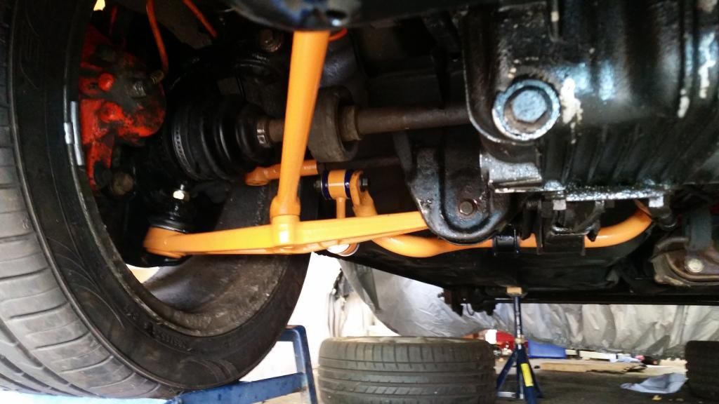
Chassis-wise. Since you asked:
I've decided to initially go for zr struts on x-power springs and a full poly bush on all new suspension and steering moving parts. I've had the steering rack refurbished too. I will be using the stiffer ZR160 rear beam (that also gives me the larger rear brakes that came with) to which I will trial the 18mm "anti roll bar" from my BRM rear beam and 2.5 degree negative camber plates. The arb is actually a strengthening bar to stiffen the beam. For the zr they just made the beam with thicker material avoiding the need for this bar. However they left the mounting points for it so you can make the beam extra stiff (possibly too stiff - we shall see).
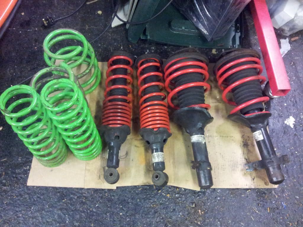
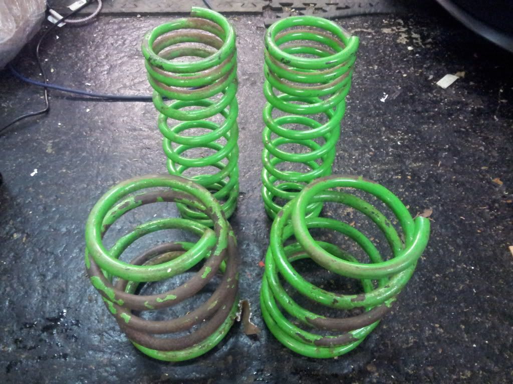
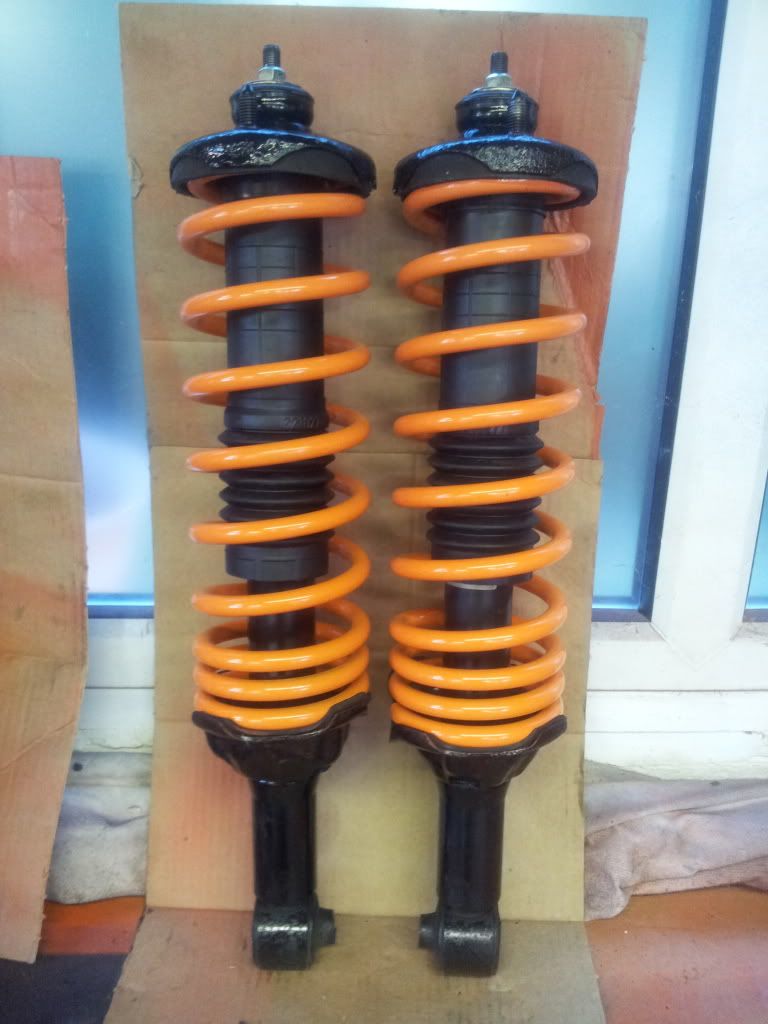
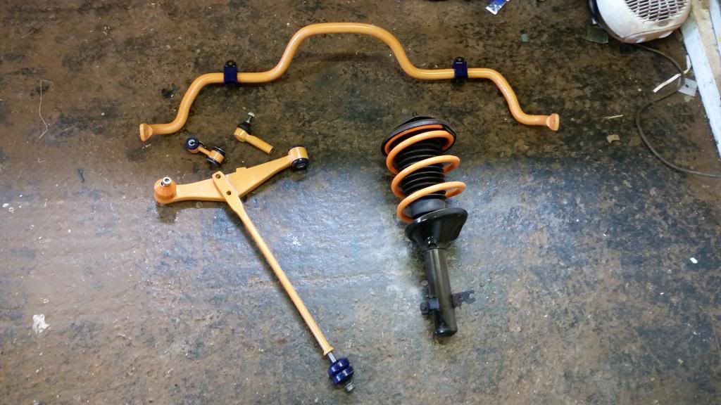
Picked up a set of ZR struts and some genuine x-power springs in generally poor condition.
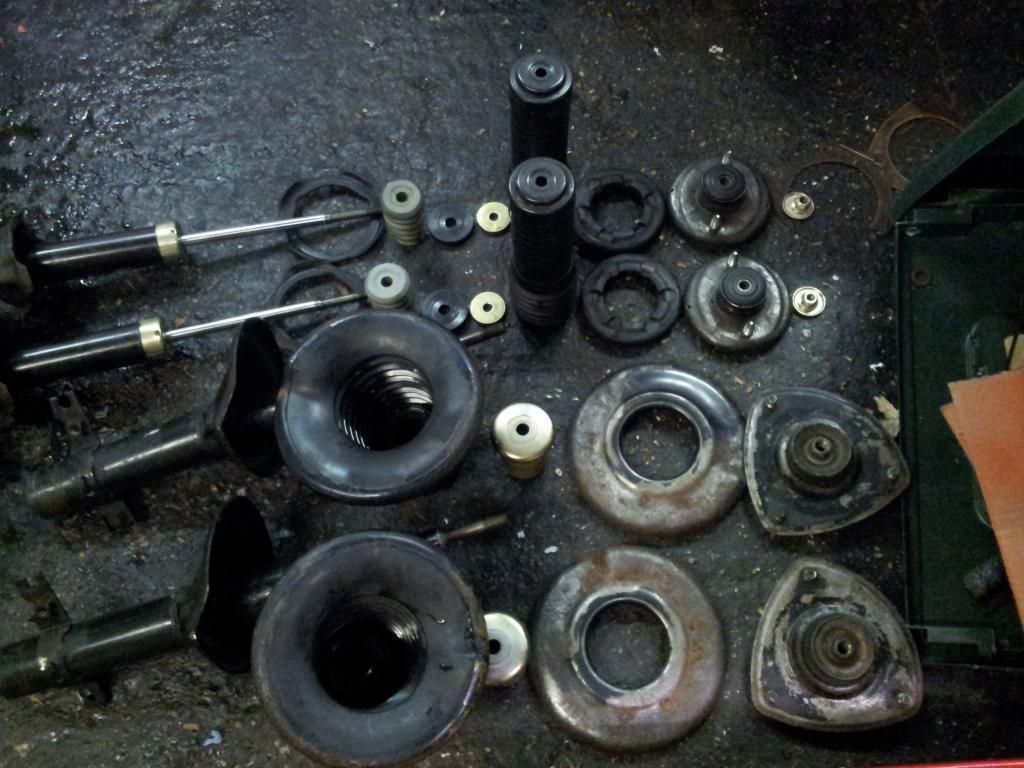
Struts stripped down for a rebuild, ended up replacing the top mounts with new standard units.
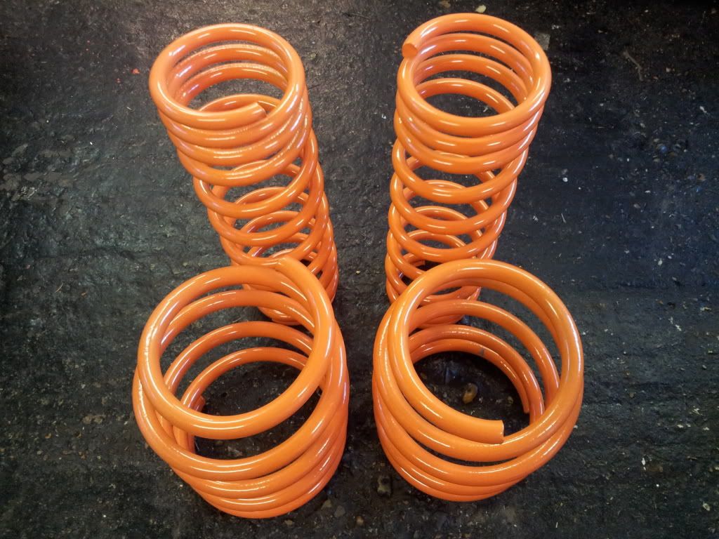
Had the X-power springs sand blasted and powder coated orange (obv)
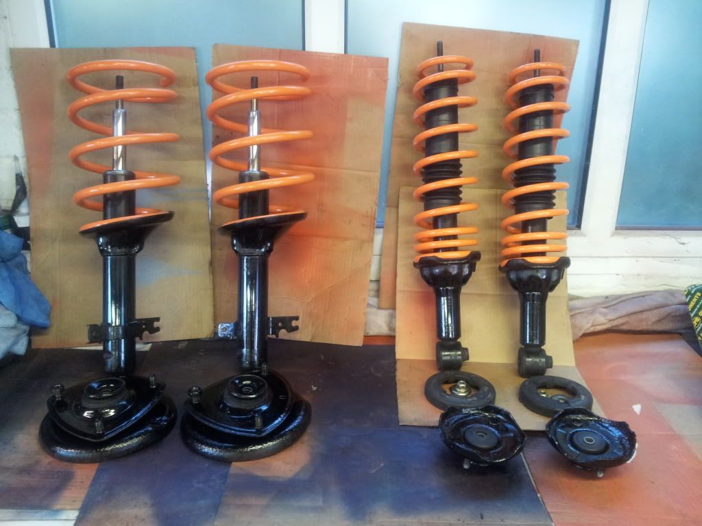
Building the struts back up
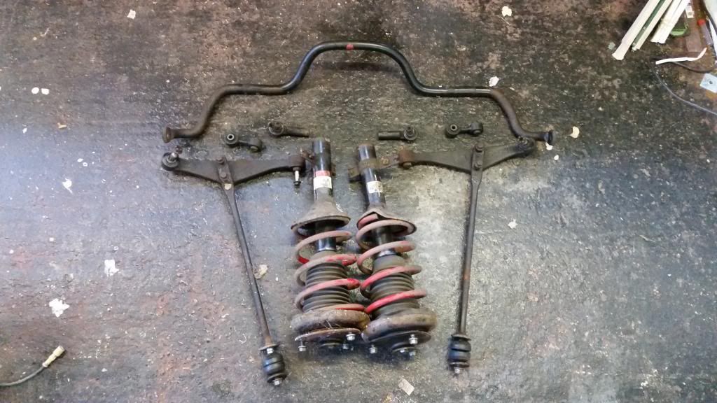
taking the old struts, lower arms, tie rods, track rod ends, drop links and ARB off the BRM:
New lower arms - removing the bushes
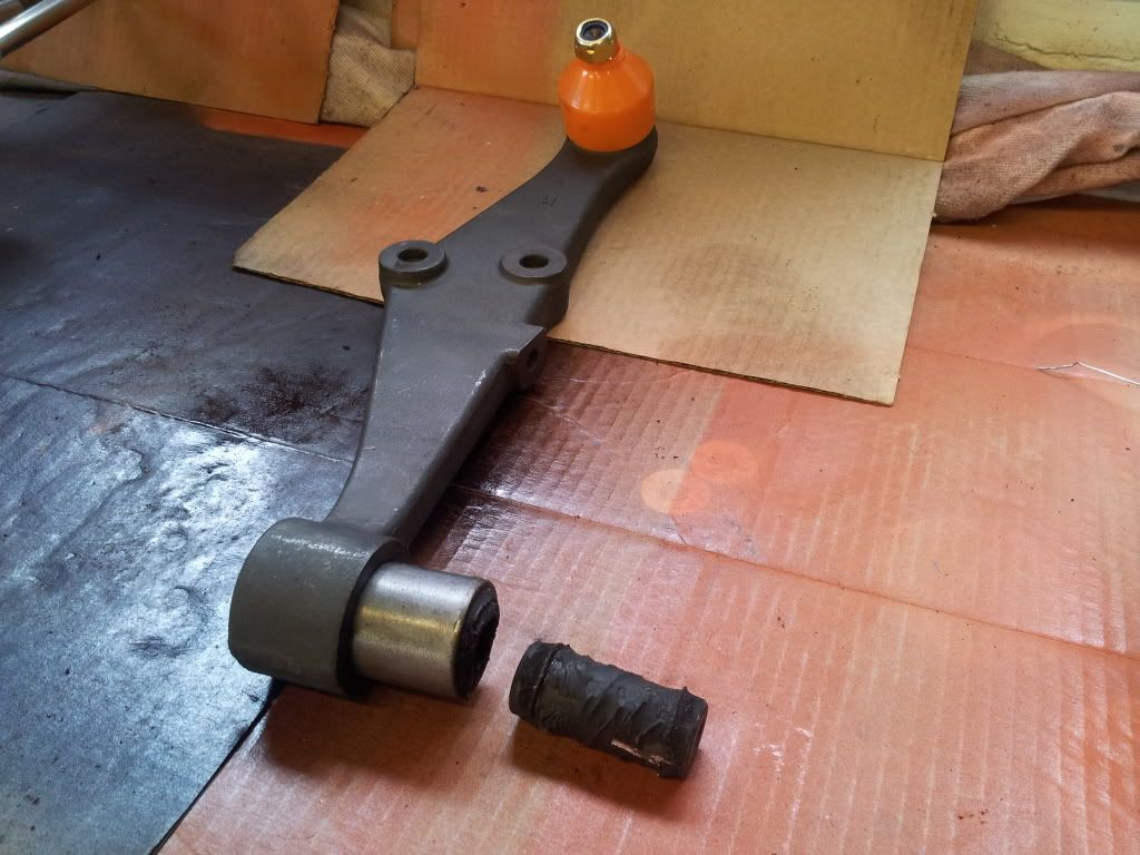
All ready for poly bushes
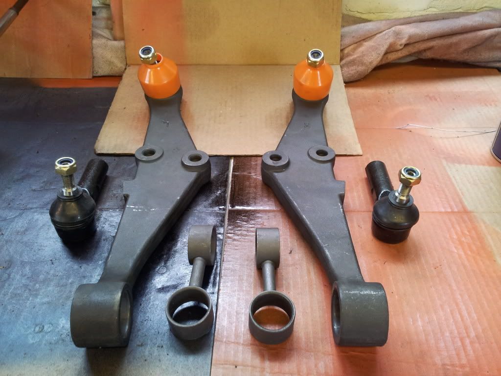
Poly bushes installed after a lick of protective paint. I only had orange...
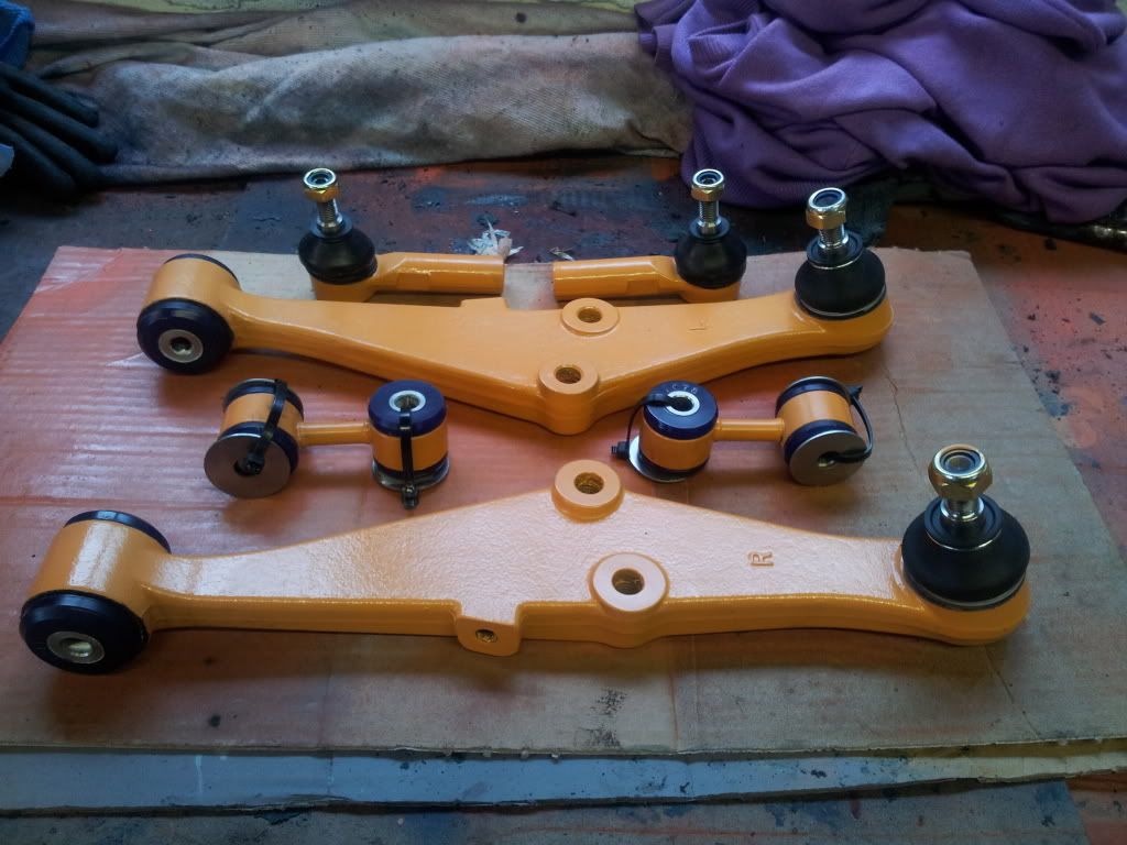
All ready to go on:
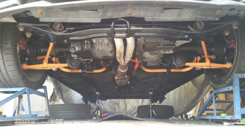
And all on. Gave the front cross member a lick of paint too - Found some black paint for that...
I also replaced the steering rack with a recon unit whilst doing this job which is a horrific task. Got it done but no pictures.
Whilst under the car I also installed the short throw (and poly bushed) gear linkage. This is a great piece of kit and gives the gear shift a really slick action. It reduces the throw on the BRM from 3rd to 4th from 10.5cm to 7.5cm. That doesn't sound a lot but trust me it really make a difference.
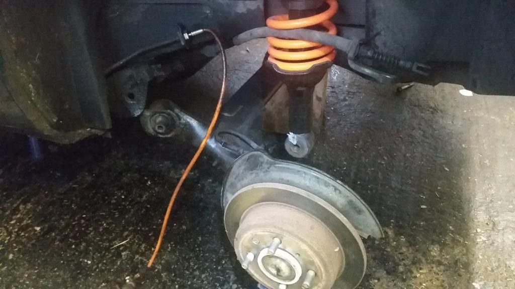
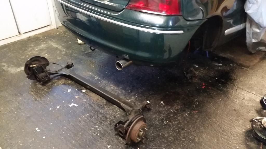
Turning attention to the rear end:
Removal of the rear beam was actually quite simple.
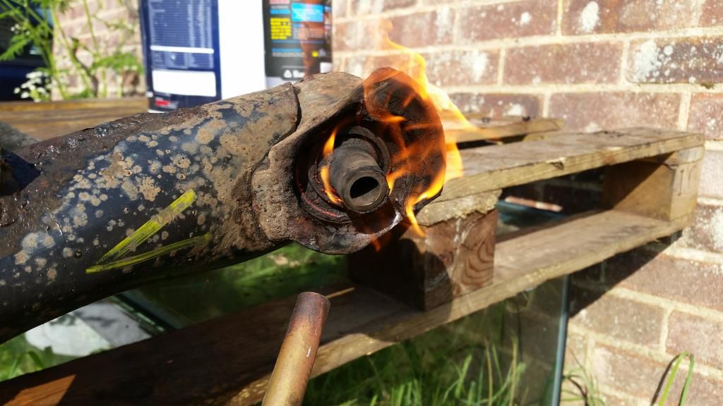
Removing the rubber bushes from the ZR beam to make way for poly. Had to burn them out! Getting the giant poly bushes in was surprisingly difficult. Had to fashion a tool out of threaded bar, nuts and spacers. Shame I didn't get any pictures of this as it took me forever to do!
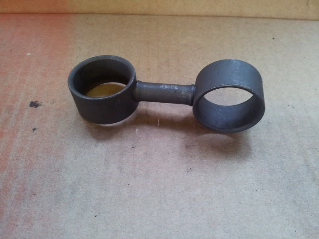
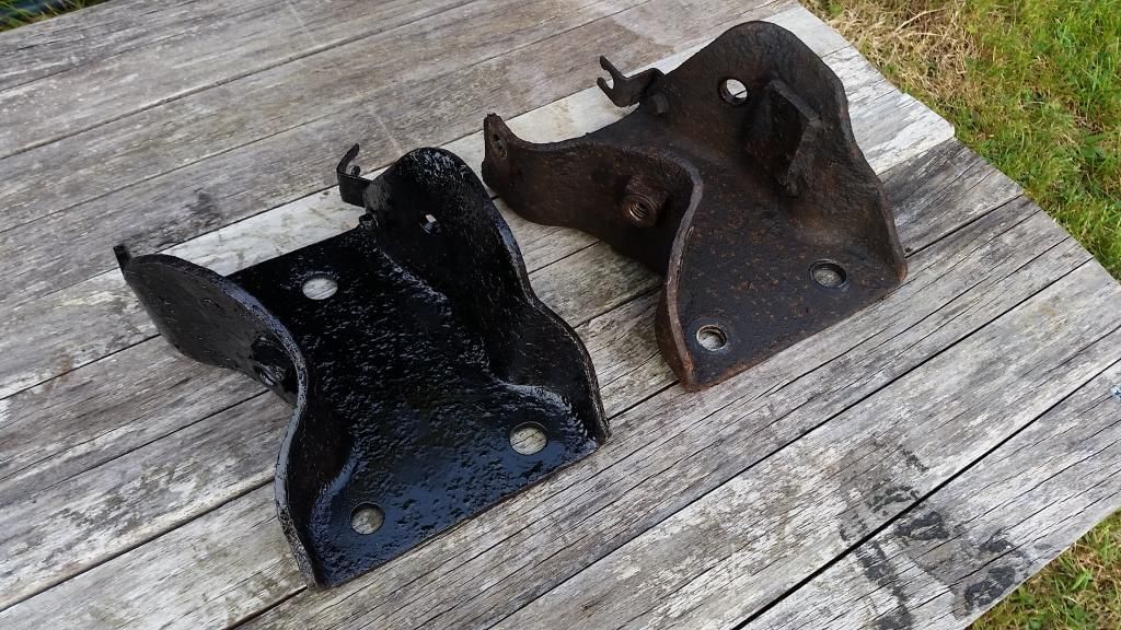
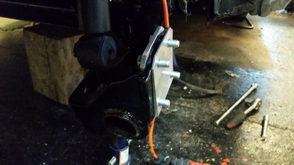
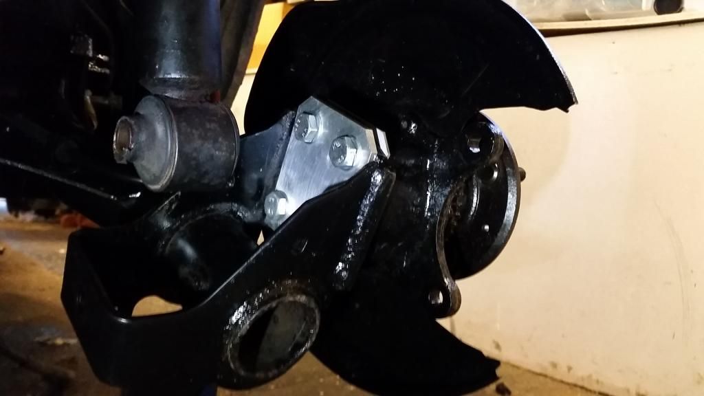
It turns out that the beam-to-chassis brackets are unique on the BRM. You'll see in the image below that the BRM bracket (on the right) has a small piece welded into it. Apparently this was to reduce lateral movement of the rear end to give more precise feel. It would have seriously hampered installation of poly bushes which only come designed for the standard 200 brackets so I had to source a set of non-BRM brackets.
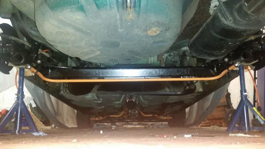
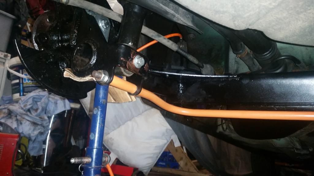
New beam in complete with (ahem) orange ARB I extracted at great effort from the BRM beam. The ZR beam is apparently stiffer so the ARB (which is not really an ARB in the classic sense - it just adds stiffness) is not needed. However it still has the bracketry for one so I thought I'd give it a go. This might make it a bit flightly on the road so if it's too much I'll take it off. It'll be a shame though as I had to perform grinder cutting surgery to get it off without damaging it. the 4" or so spacers you can see at each mounting end are new stainless spacers I had to fabricate as one of the old spacers had to be hacked to bits to get it off (it had basically welded to the bar with corrosion).
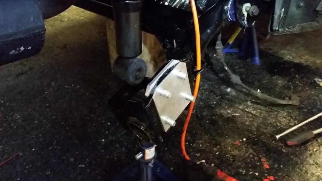
Also installed some negative camber plates. I was originally going to go for 1.5 degrees as this will be a road car. However I got talked into 2.5 degrees. Will see how they feel on the road. If too much then I'll swap for 1.5 degrees later.
And how she currently sits on this setup. a Little high on the rear still. That might just be the uneven driveway. Suspect I may end up going with coilevers but will let it sit like this for the time being. The wheels are temporary as I wanted something I knew would fit over the big brake kit I'll be using (the BRM cosmos wheels will not work unfortunately) . Eventually I'll source something in 17" that has similar 6-spoke design as the cosmos. Saying that, the OZ superlegerras have grown on me.
You'll notice the bonnet vents. That's a tale for another day...
Chassis-wise. Since you asked:
I've decided to initially go for zr struts on x-power springs and a full poly bush on all new suspension and steering moving parts. I've had the steering rack refurbished too. I will be using the stiffer ZR160 rear beam (that also gives me the larger rear brakes that came with) to which I will trial the 18mm "anti roll bar" from my BRM rear beam and 2.5 degree negative camber plates. The arb is actually a strengthening bar to stiffen the beam. For the zr they just made the beam with thicker material avoiding the need for this bar. However they left the mounting points for it so you can make the beam extra stiff (possibly too stiff - we shall see).
Picked up a set of ZR struts and some genuine x-power springs in generally poor condition.
Struts stripped down for a rebuild, ended up replacing the top mounts with new standard units.
Had the X-power springs sand blasted and powder coated orange (obv)
Building the struts back up
taking the old struts, lower arms, tie rods, track rod ends, drop links and ARB off the BRM:
New lower arms - removing the bushes
All ready for poly bushes
Poly bushes installed after a lick of protective paint. I only had orange...
All ready to go on:
And all on. Gave the front cross member a lick of paint too - Found some black paint for that...
I also replaced the steering rack with a recon unit whilst doing this job which is a horrific task. Got it done but no pictures.
Whilst under the car I also installed the short throw (and poly bushed) gear linkage. This is a great piece of kit and gives the gear shift a really slick action. It reduces the throw on the BRM from 3rd to 4th from 10.5cm to 7.5cm. That doesn't sound a lot but trust me it really make a difference.
Turning attention to the rear end:
Removal of the rear beam was actually quite simple.
Removing the rubber bushes from the ZR beam to make way for poly. Had to burn them out! Getting the giant poly bushes in was surprisingly difficult. Had to fashion a tool out of threaded bar, nuts and spacers. Shame I didn't get any pictures of this as it took me forever to do!
It turns out that the beam-to-chassis brackets are unique on the BRM. You'll see in the image below that the BRM bracket (on the right) has a small piece welded into it. Apparently this was to reduce lateral movement of the rear end to give more precise feel. It would have seriously hampered installation of poly bushes which only come designed for the standard 200 brackets so I had to source a set of non-BRM brackets.
New beam in complete with (ahem) orange ARB I extracted at great effort from the BRM beam. The ZR beam is apparently stiffer so the ARB (which is not really an ARB in the classic sense - it just adds stiffness) is not needed. However it still has the bracketry for one so I thought I'd give it a go. This might make it a bit flightly on the road so if it's too much I'll take it off. It'll be a shame though as I had to perform grinder cutting surgery to get it off without damaging it. the 4" or so spacers you can see at each mounting end are new stainless spacers I had to fabricate as one of the old spacers had to be hacked to bits to get it off (it had basically welded to the bar with corrosion).
Also installed some negative camber plates. I was originally going to go for 1.5 degrees as this will be a road car. However I got talked into 2.5 degrees. Will see how they feel on the road. If too much then I'll swap for 1.5 degrees later.
And how she currently sits on this setup. a Little high on the rear still. That might just be the uneven driveway. Suspect I may end up going with coilevers but will let it sit like this for the time being. The wheels are temporary as I wanted something I knew would fit over the big brake kit I'll be using (the BRM cosmos wheels will not work unfortunately) . Eventually I'll source something in 17" that has similar 6-spoke design as the cosmos. Saying that, the OZ superlegerras have grown on me.
You'll notice the bonnet vents. That's a tale for another day...
Edited by Stuballs on Wednesday 3rd January 13:19
rb5er said:
Looks great. How does it drive if at all?
A bit all over the place but geometry not set up yet so hard to say. I expect I may end up undoing some of the suspension mods but nothing I’ve done is not easily reversible.andburg said:
amazing how many names I still recognise here from .org and no one is left there!
I know! Seeing a few familiar names pop up. .org seems mostly for MGF and TF owners now.FWDRacer said:
If this was a VW, people would be fisting off over it.
I love the fact it is a BRM Rover. OP-> Top skills. Bit heavy on the Orange tho'
Thanks mate! Yeah orange is a bit heavy but the engine bay when finished will be fairly subtle.I love the fact it is a BRM Rover. OP-> Top skills. Bit heavy on the Orange tho'
300bhp/ton said:
Just out of curiosity, what sort of cost had this rebuild involved?
Absolutely everything in the engine bay including nuts, bolts, gaskets probably about £9k. However I’m currently in the process of overhauling the head again and going solid cam so add another grand plus. I know it’s silly money to spend on a Rover but for me it’s less about the end result and more about my enjoyment of tackling the project myself. I’m not a mechanic (just a self-taught hobbyist like a lot of guys)– I’ve used this as a learning process as much as anything else. That said, I do want something special at the end!Time to get the exhaust done.
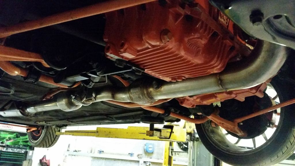
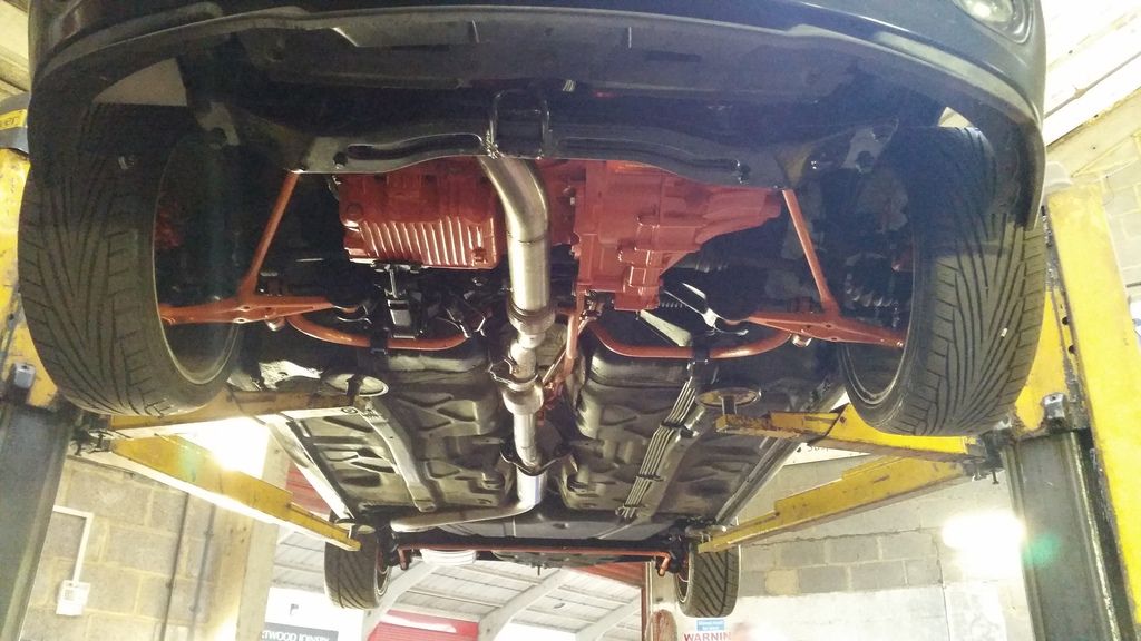
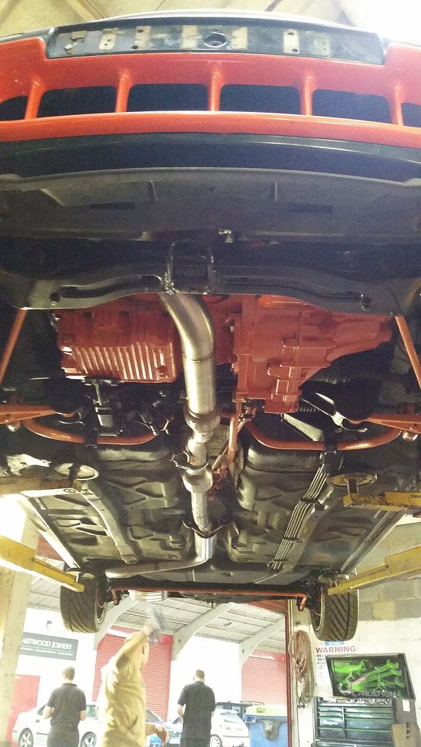
Obviously being a non turbo car I had to at least sort the downpipe. I initially considered just having a downpipe made and mating it to the existing cat-back system. But then I figured if I'm having the car trailered somewhere and paying for fabrication, I may as well go the whole hog and have a full system made.
I had a few options but went with Fast Road Conversions in Ashford (Powerspeed). They made me a full turbo-back 2.5" system with a sports cat and managed to squeeze in a massive 3" downpipe.
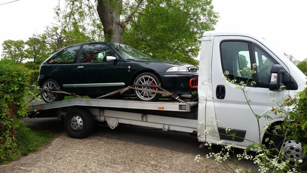
First time out of the garage for a while. Gave her a quick wipe down as she was covered in generic garage dust.
Obviously not running at this point so had to arrange for transport there and back
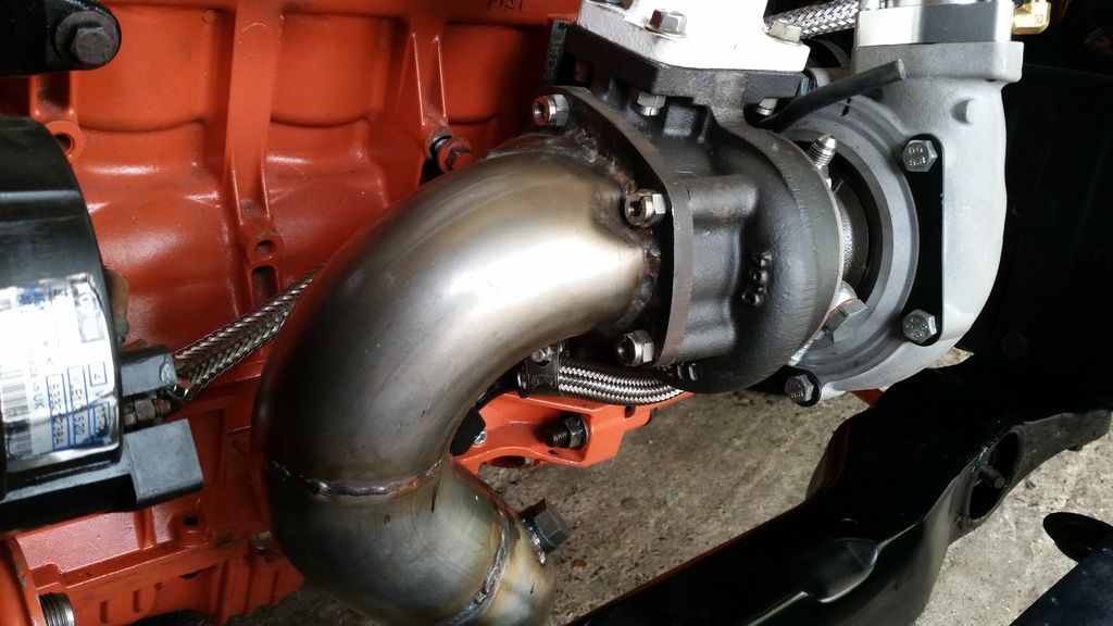
3" downpipe! You can see it runs quite close to the alternator so done heat shielding will be needed.
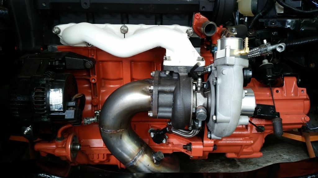
Downsizes to 2.5" after the flexi
Back box is not the prettiest thing so I'll paint that black at some point.
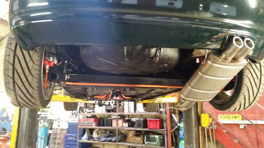
Love this shot:

And with some heat wrap and my DIY heat shield.
I was generally very happy although there was a small hiccup when a miscommunication left me without a cat. It got sorted but it does mean I now have a slip-on join before the cat - not the end of the world I suppose.
Obviously being a non turbo car I had to at least sort the downpipe. I initially considered just having a downpipe made and mating it to the existing cat-back system. But then I figured if I'm having the car trailered somewhere and paying for fabrication, I may as well go the whole hog and have a full system made.
I had a few options but went with Fast Road Conversions in Ashford (Powerspeed). They made me a full turbo-back 2.5" system with a sports cat and managed to squeeze in a massive 3" downpipe.
First time out of the garage for a while. Gave her a quick wipe down as she was covered in generic garage dust.
Obviously not running at this point so had to arrange for transport there and back
3" downpipe! You can see it runs quite close to the alternator so done heat shielding will be needed.
Downsizes to 2.5" after the flexi
Back box is not the prettiest thing so I'll paint that black at some point.
Love this shot:
And with some heat wrap and my DIY heat shield.
I was generally very happy although there was a small hiccup when a miscommunication left me without a cat. It got sorted but it does mean I now have a slip-on join before the cat - not the end of the world I suppose.
Edited by Stuballs on Wednesday 3rd January 13:21
cirian75 said:
np, thats why build pics are great, people will see things others don't so 99% of the problems are nipped in the bud right at the start.
maybe some wrap or shield around the section that goes past the sump too
I have reflective heat shield on the sump itself but wanted to avoid wrapping that section of the downpipe as I'd be worried about it soaking up any oil leaks and catching fire (paranoia perhaps but you hear horror stories!) maybe some wrap or shield around the section that goes past the sump too
Since that picture was taken I've redone the oil drain so it has more of a downward angle and is further away from the exhaust housing. But I will definitely sort some heat shield for it!
Gassing Station | Readers' Cars | Top of Page | What's New | My Stuff