Classic mini 16V turbo A series, 6 speed seqential
Discussion


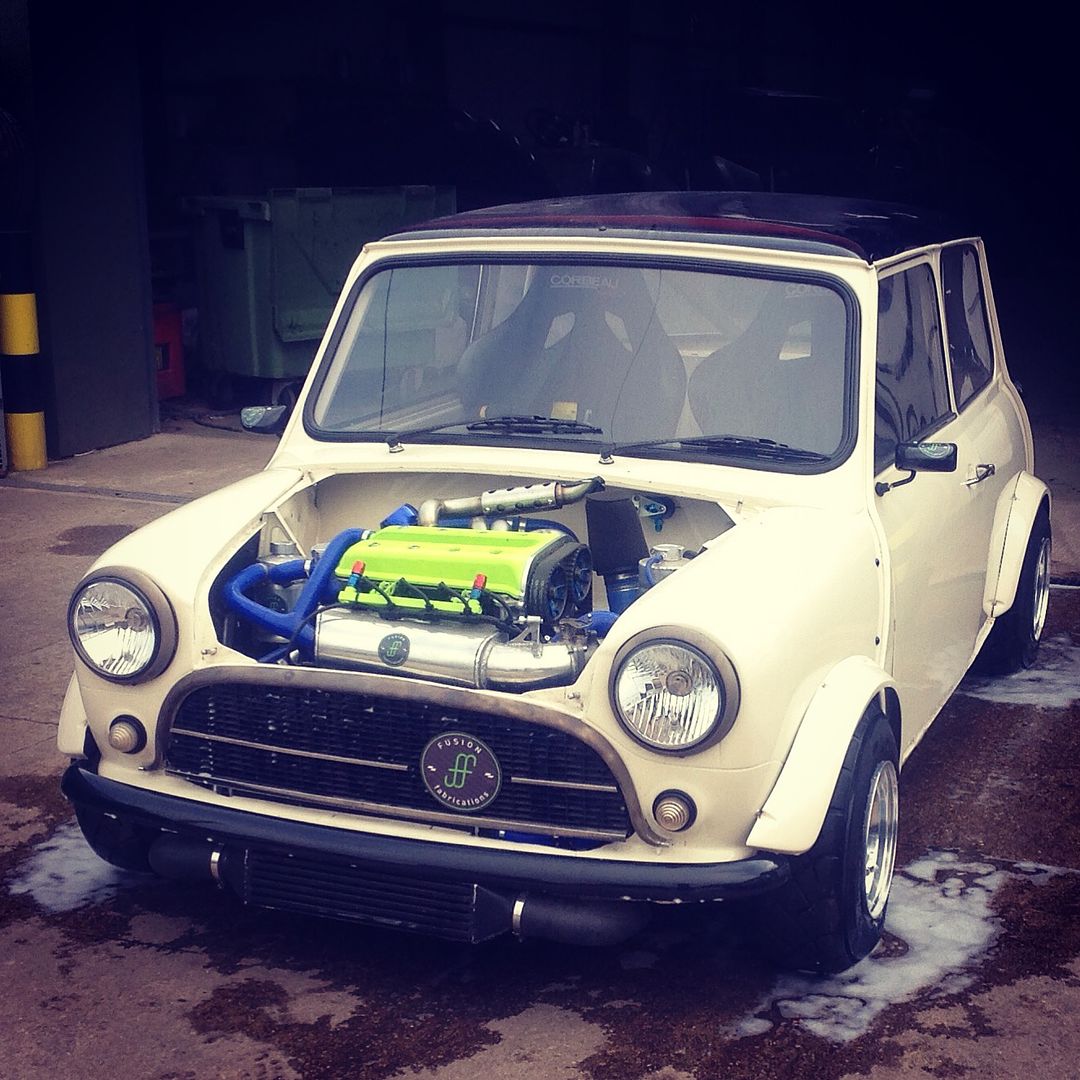
Hi, this is my mini that I have owned for about 14 years now. It's now on its 3rd complete rebuild and 6th/7th engine rebuild. 😂 I took it apart about 4 years ago for an engine refresh and ended up rebuild the entire car in the quest for more power, less weight...more speed!
The shell and generally everything else has been lightened where it can be. I still have plenty to do, but it's sub 500kgs which was the main aim 4 years ago.
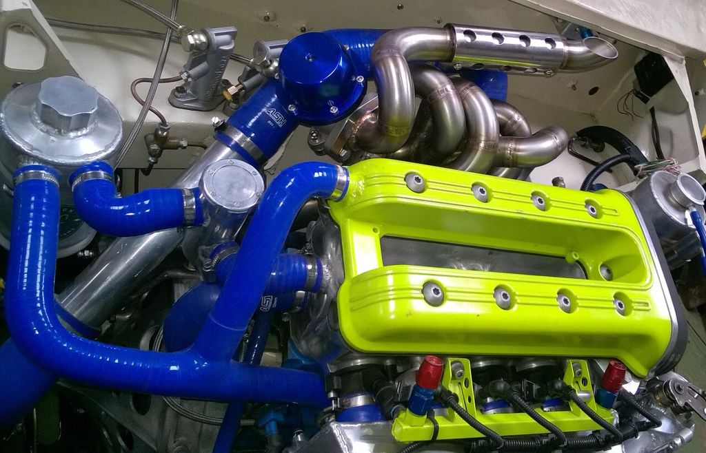
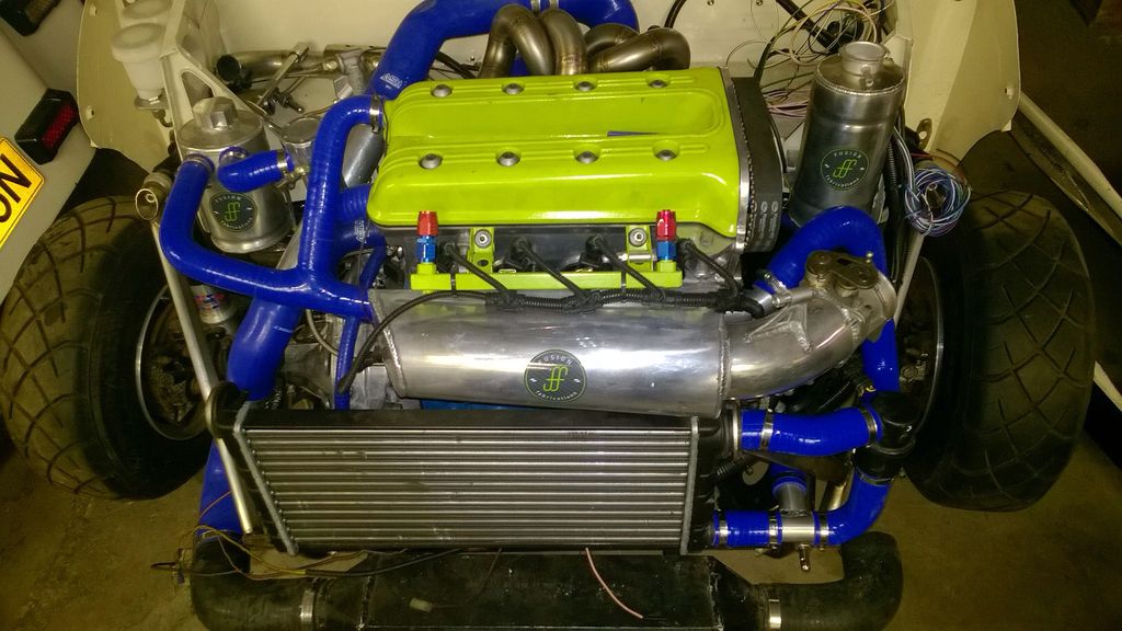
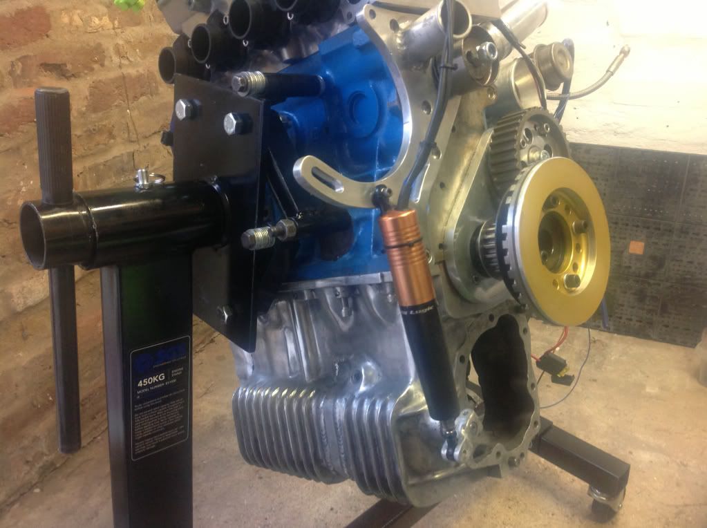
The engine is an A series block, with a BMW K1100 16V head, running EFI, turbo.
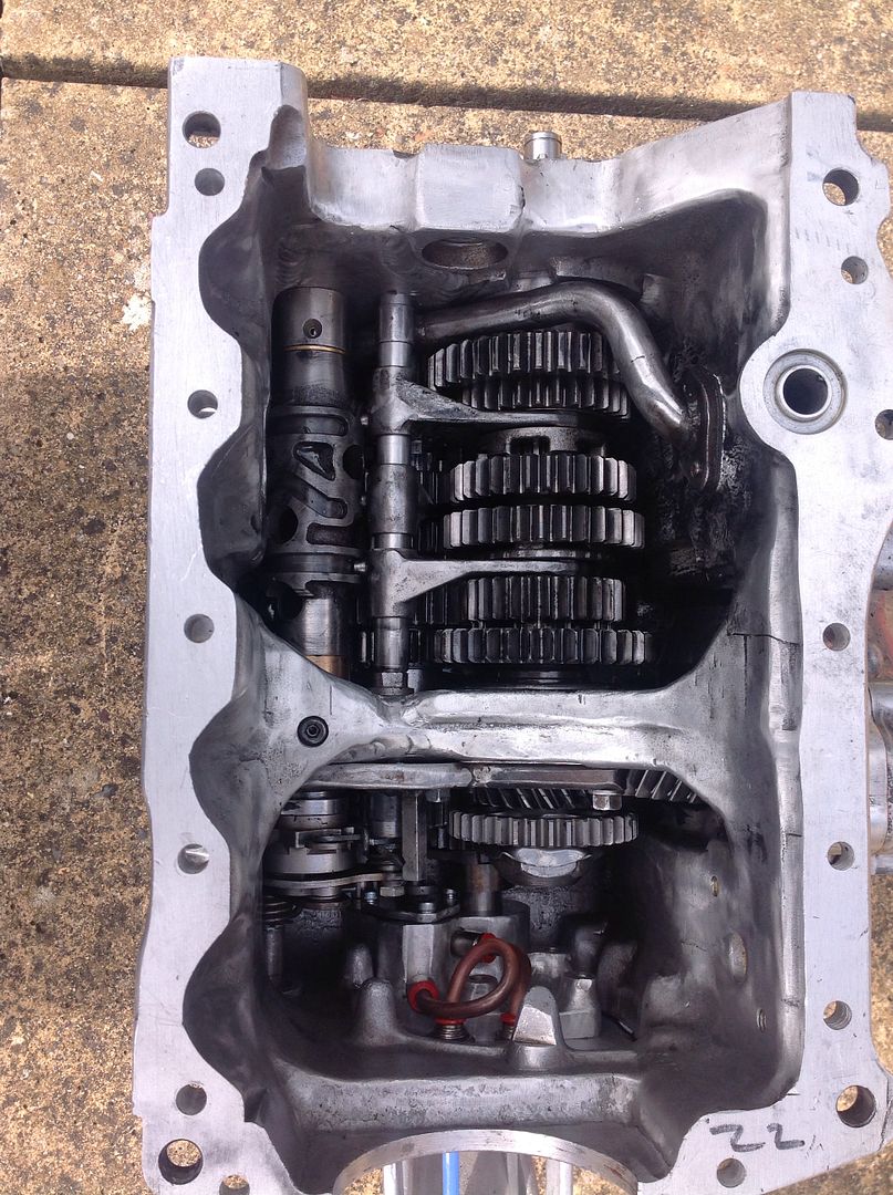
The gearbox is an A Series casting modified to take a Honda VFR 6 speed gear set.
I still have plenty of bits to finish off, but it is slowly but surely getting closer to being finished.
The shell and generally everything else has been lightened where it can be. I still have plenty to do, but it's sub 500kgs which was the main aim 4 years ago.
The engine is an A series block, with a BMW K1100 16V head, running EFI, turbo.
The gearbox is an A Series casting modified to take a Honda VFR 6 speed gear set.
I still have plenty of bits to finish off, but it is slowly but surely getting closer to being finished.
57Ford said:
Looks like incredible fun! This was a dream when I was 13 / 14 years old. Unfortunately I've never had space to do it yet but there's time yet... Well done
Thanks, yeah it is good fun to drive and surprises a few people. After 4 yeas of not driving it, it's going to be a bit of shock after driving a Diesel van everyday.Sf_Manta said:

How much is it making?! Given the high flow head and turbo.. must be what? 160-180bhp or there abouts.
Must be like having a bike engine and a stuggle to get the power down once the boost winds up Top work!

fttm said:
Nice work but looks scary as hell , what have you done to the shell ?
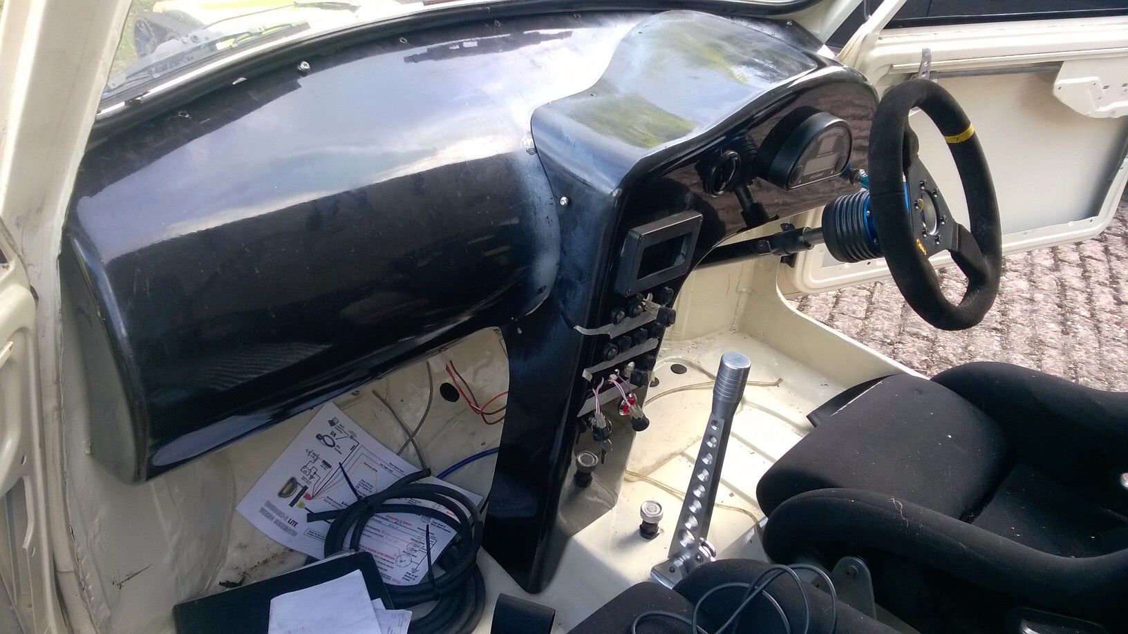
The shell has had rear bins removed and rear bench, battery box removed and every unused bracket removed. It's got ally skinned doors, fibreglass front, and fibreglass boot lid. The bulkhead has been remade and dash rails removed. Rear subframe replaced with beam, front subframe lightened. Pretty much everything that bolts on to the shell has had weight removed from it.vrooom said:
Bloody hell. how well does the VFR gearbox hold up? have you found the limitation ?
The gearbox is the latest modification, it has been bench testing and run through heat cycles to check runnign clearances etc, but not put under power yet....it's going to a nervous moment! I have been told that these boxes are good for over 400bhp on the turbo'd drag bikes.dom9 said:
Would love to hear more about the gearbox conversion; how you worked out it could be done, why the VFR gears, what youv done with the diff etc!
I will post some pictures up later on. I saw some pictures of someone in Aus that had done the conversion, and thought I'd have a go basically, just as a bit of an engineering exercise.It ended up a lot more complex than I originally thought, but I got there eventually.
Thanks for the comments. It could take a while to write up the whole gearbox build, but here are the main mods done to the casing etc...
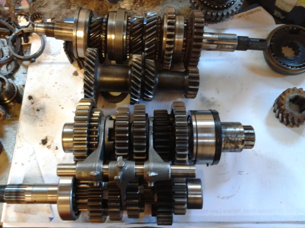
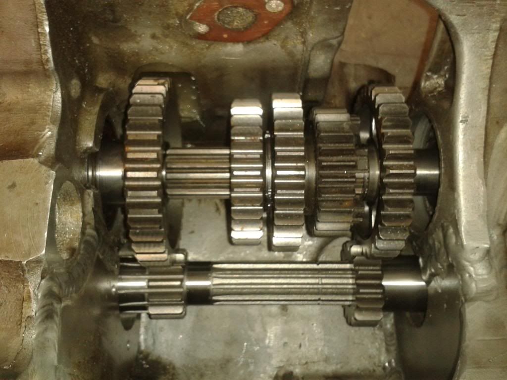
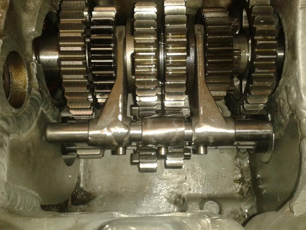
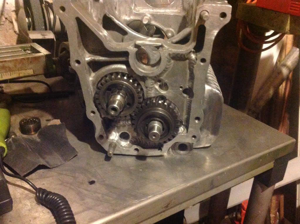
I started comparing the two gearsets, and measuring shaft centres to see where the input shaft one align in the casing. The 3rd motion shaft was always going to stay in the stay position as I used this as the datum point. It also allowed me to keep the standard CWP and allowed standard mesh of the drops gears also.
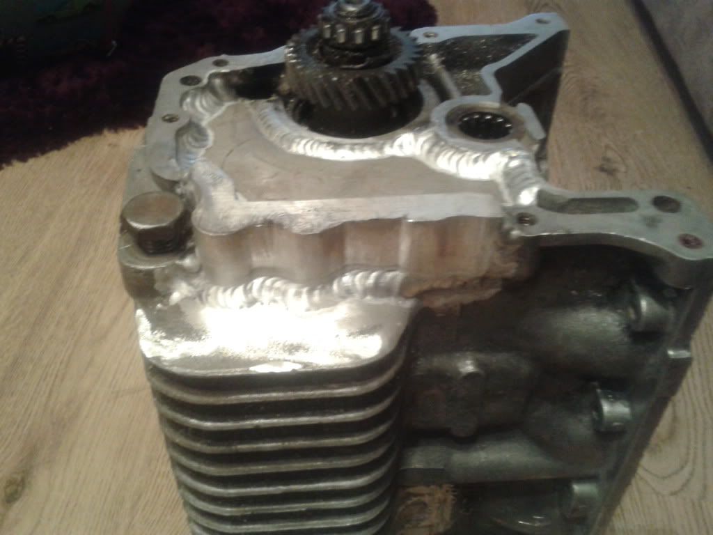
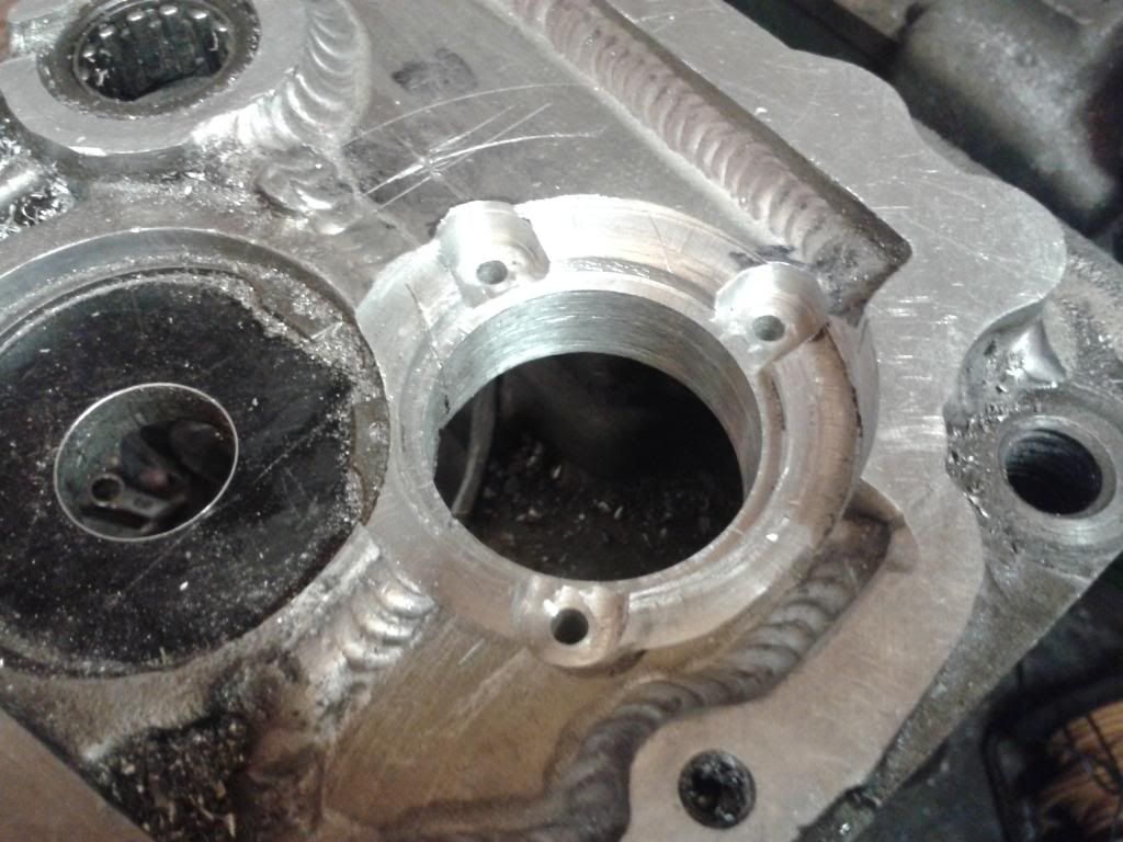
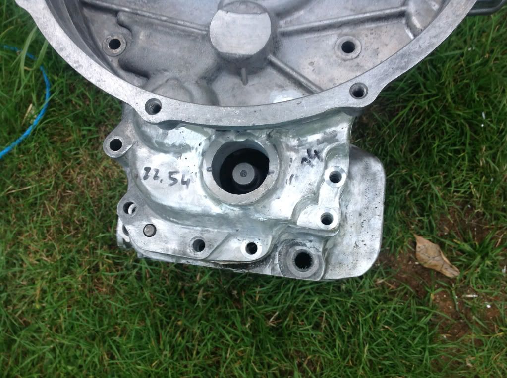
The case was then chopped to allow for new blank plates to be welded in for new shaft locations.
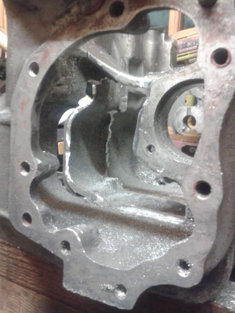
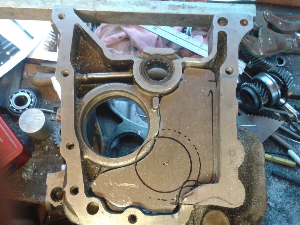
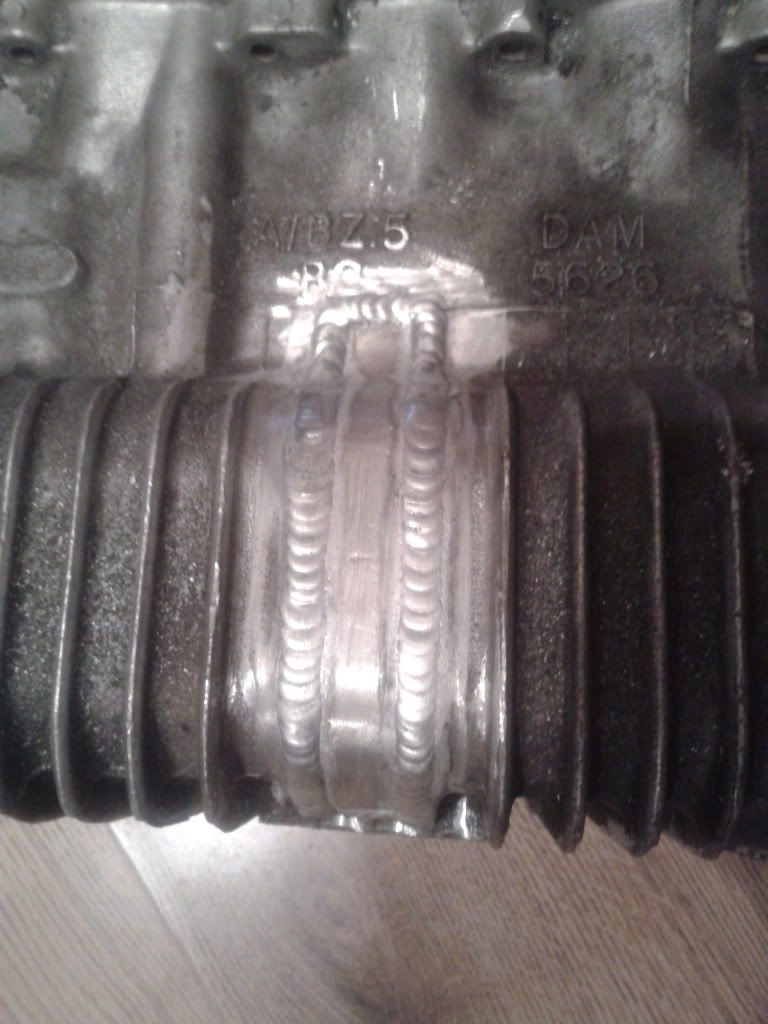
New plates welded in place.
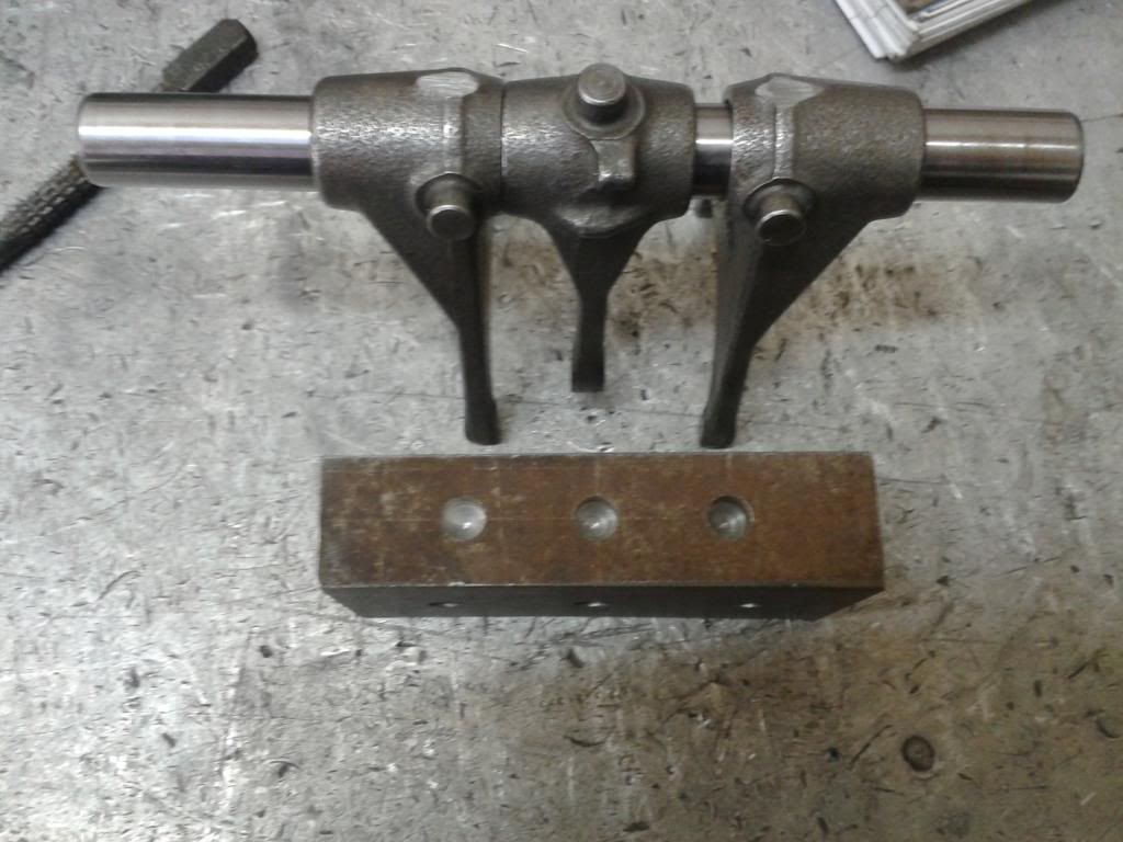
A Jig was then made and a pointer for the selector fork shaft to work out that shaft centre in comparison to the others.
I started comparing the two gearsets, and measuring shaft centres to see where the input shaft one align in the casing. The 3rd motion shaft was always going to stay in the stay position as I used this as the datum point. It also allowed me to keep the standard CWP and allowed standard mesh of the drops gears also.
The case was then chopped to allow for new blank plates to be welded in for new shaft locations.
New plates welded in place.
A Jig was then made and a pointer for the selector fork shaft to work out that shaft centre in comparison to the others.
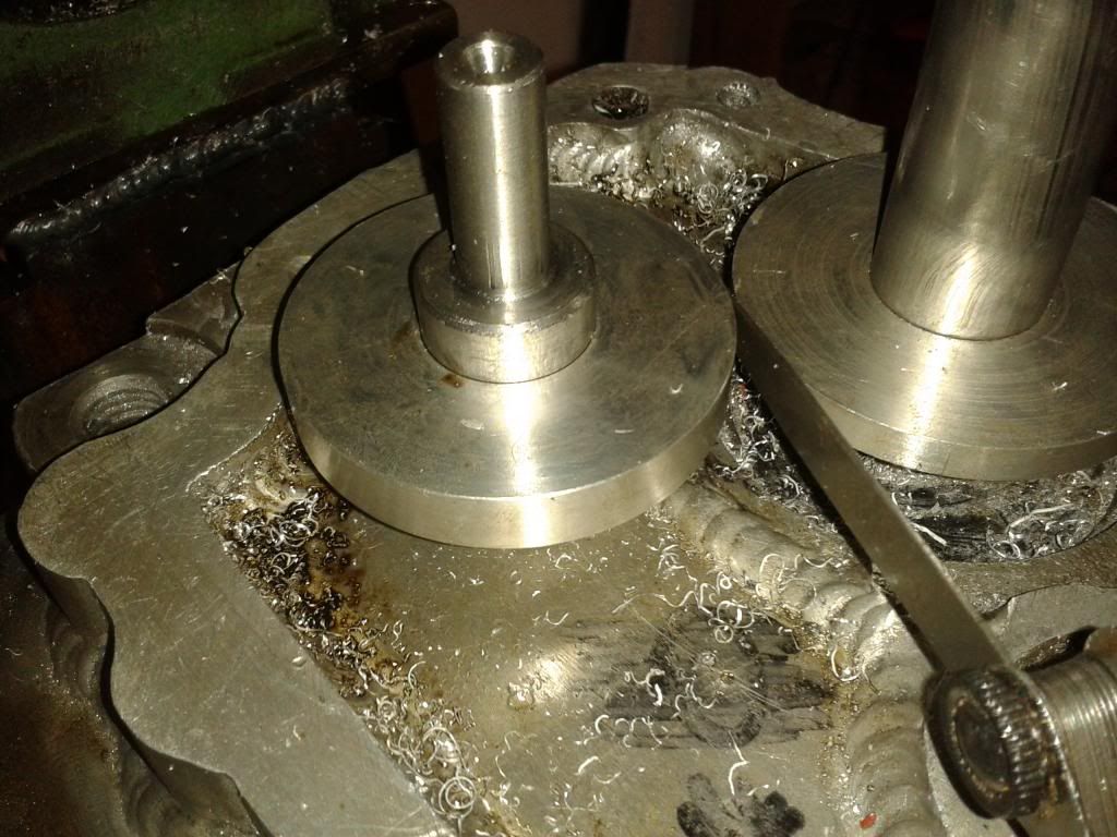
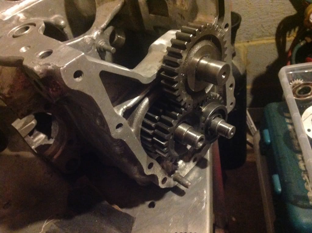
The casing was the bored to the correct shaft centres. To check clearances on the machine to ensure correct backlash clearance, I made some bungs for the bearings inserted two shafts, then two discs machined to the same OD and use a feeler to measure the backlash.
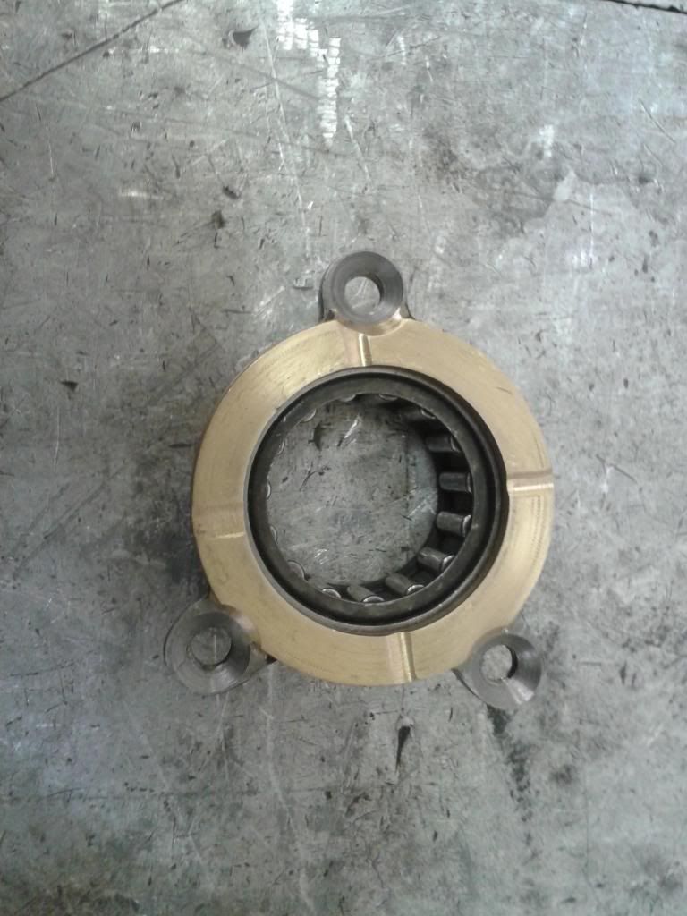
A removable bearing carrier was then machined up. It had to be removable to allow the shaft to be fitted from the end and gears assembled in situ. The was EN36 main body Phosphor bronze bush silver soldered onto carrier.
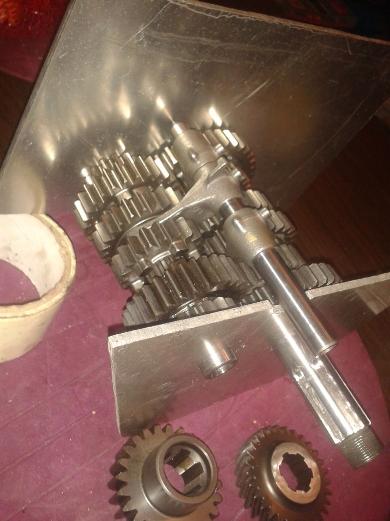
This is the standard mini 3rd motion and VFr output shaft, so I need to make a bike shaft that had the mini pinion spline, and mini 1st motion bearing surface on the end, so I designed a shaft and had this made.
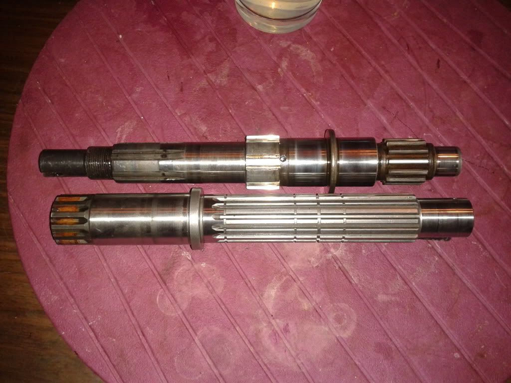
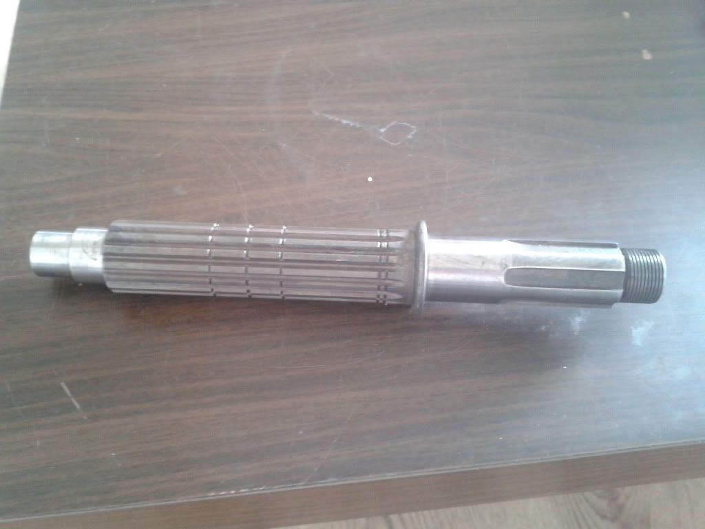
A removable bearing carrier was then machined up. It had to be removable to allow the shaft to be fitted from the end and gears assembled in situ. The was EN36 main body Phosphor bronze bush silver soldered onto carrier.
This is the standard mini 3rd motion and VFr output shaft, so I need to make a bike shaft that had the mini pinion spline, and mini 1st motion bearing surface on the end, so I designed a shaft and had this made.
Edited by Matty... on Tuesday 15th November 21:30
I then designed the second shaft to be made, this time the input shaft. This was VFR spline and fixed gear. And was extended on the input end for an additional drop gear to reverse the gears to make them rotate the correct way.
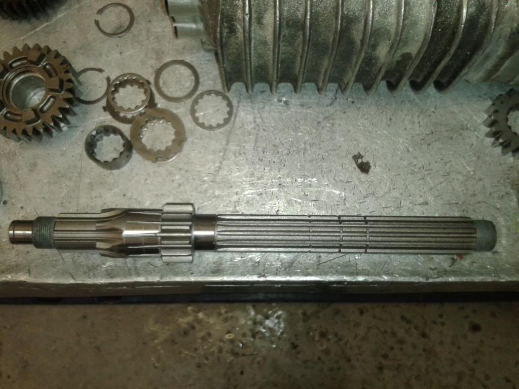
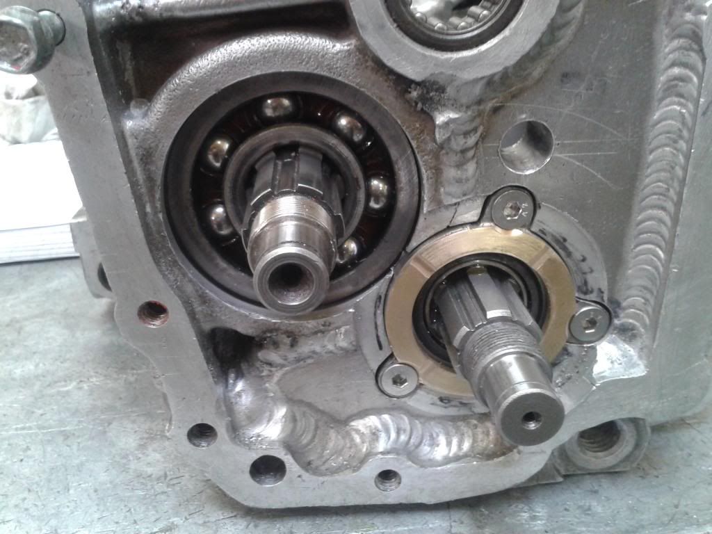
The 1st motion shaft was then modified by removing the standard gear and selector ring as these are no longer needed.
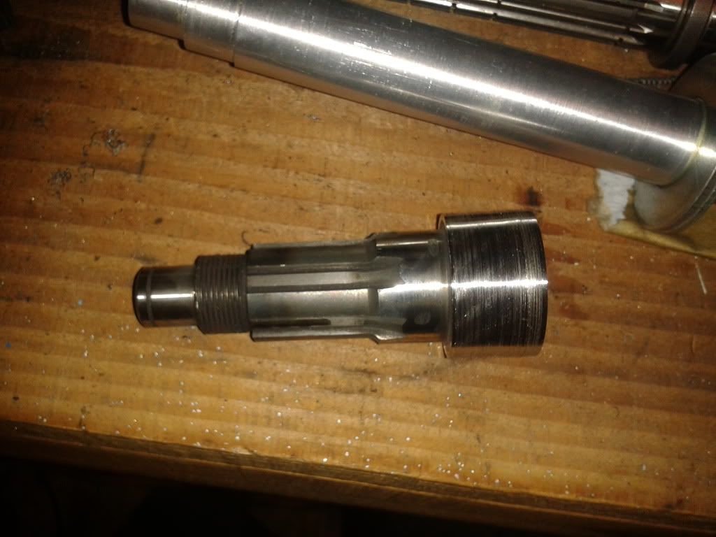
This is them roughly in position.
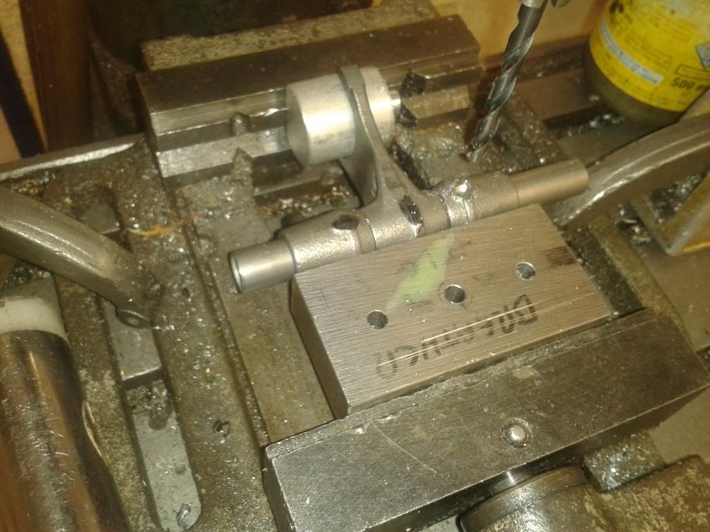
The next part to modify was the selector fork pins. As the standard selector drum position wouldn't work. I made a jig and re drilled the new pin positions. The new pins were made from silver steel and hardened.
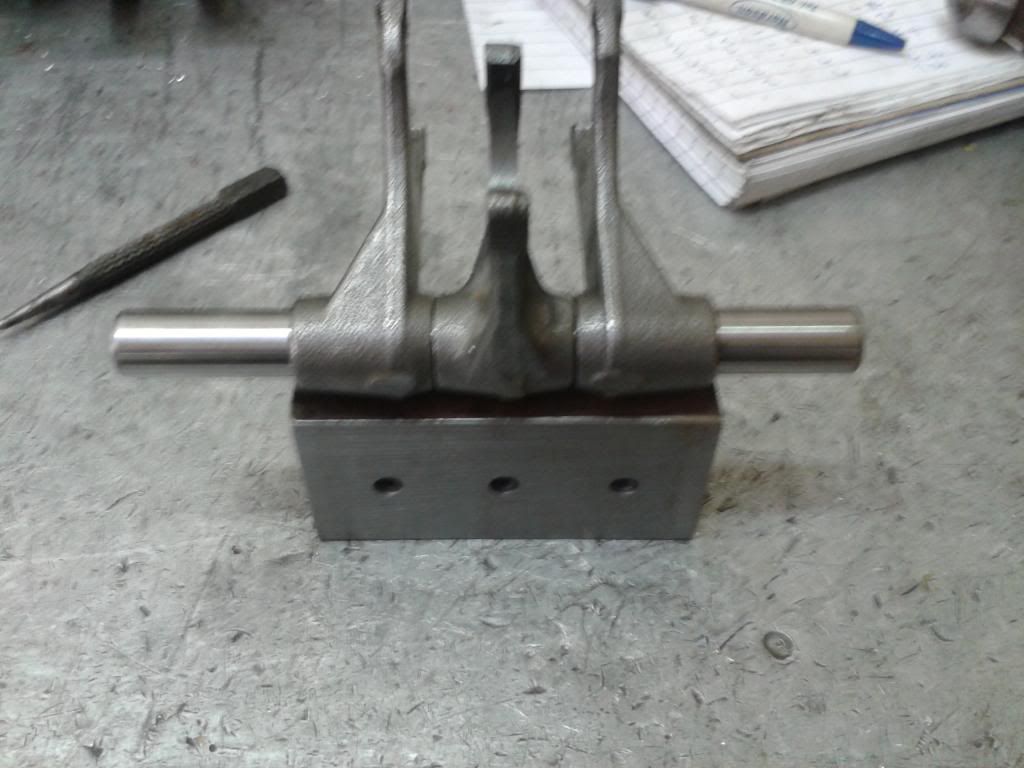
They are now in the correct position for selector.
The 1st motion shaft was then modified by removing the standard gear and selector ring as these are no longer needed.
This is them roughly in position.
The next part to modify was the selector fork pins. As the standard selector drum position wouldn't work. I made a jig and re drilled the new pin positions. The new pins were made from silver steel and hardened.
They are now in the correct position for selector.
Dr G said:
This is absolutely awesome! I love the work that went into the gearbox build particularly.
Can I ask if that relates to your day-job/training or you're just a very, very keen amateur*?
I used be an engine builder working on vintage Bugatti's, so I am quite used to repairing castings and making parts, as we used to manufacture complete new engines. I had access to the right machines too for the job!Can I ask if that relates to your day-job/training or you're just a very, very keen amateur*?
- not that amateur is a remotely appropriate term.
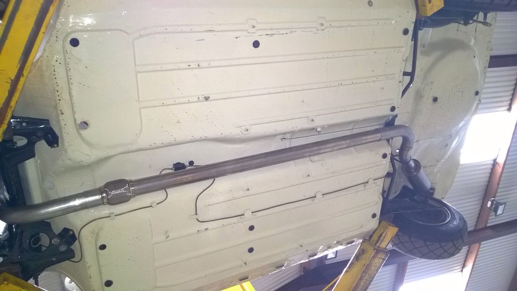
I now have my own company where I make custom exhaust systems, inlet manifolds, EFI conversions etc... Pretty much anything to do with cars/bikes and fabricating custom parts.
shalmaneser said:
Amazing work but the thought of welding on cast aluminum makes me a bit unhappy!
Best of luck with the whole thing, I hope it stays together!
I do to! I look at it as nothing ventured nothing gained.Best of luck with the whole thing, I hope it stays together!
To be honest I'm not to worried about the welding side of things, it's other parts like bearings that I am concerned with, whether they will cope with the shock loadings etc.. Also the dogs on the gears, obviously these have been designed with the weight of a bike crank in mind, not something 4 times that weight taking up the drive each gear change.
mwstewart said:
Top work! 
How is everything holding up in the gearbox? Have any of the tolerances changed since its had a bit of use?
It's still untested currently, ive got the rest of the car to finish building. I ran several bench tests running it up to 120 degrees C, shifting up and down gears fast slow speed etc and measured endfloat and backlash throughout and everything looks good on that front.How is everything holding up in the gearbox? Have any of the tolerances changed since its had a bit of use?
AdamIndy said:
Epic engineering! Love it!
What have you done about a reverse gear gear? Or is it a case of get out and push?
It has a reverse gear, this was one of the hardest parts to sort, as I had to ad an extra idler gear to reverse the shaft and room was limited after everything else was in place! What have you done about a reverse gear gear? Or is it a case of get out and push?
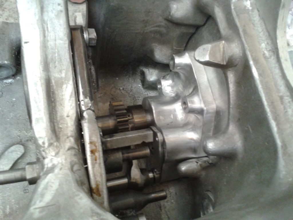
I ended up using a splined hub from another pinion and the sycro hub and gear from the original mini first gear, the idler was the mini 1st gear with the teeth beveled as they are now a crash gear. The reverse gear is operated by an air piston inside the box.
This is the gear arrangement. With selector fork from another bike gearbox.
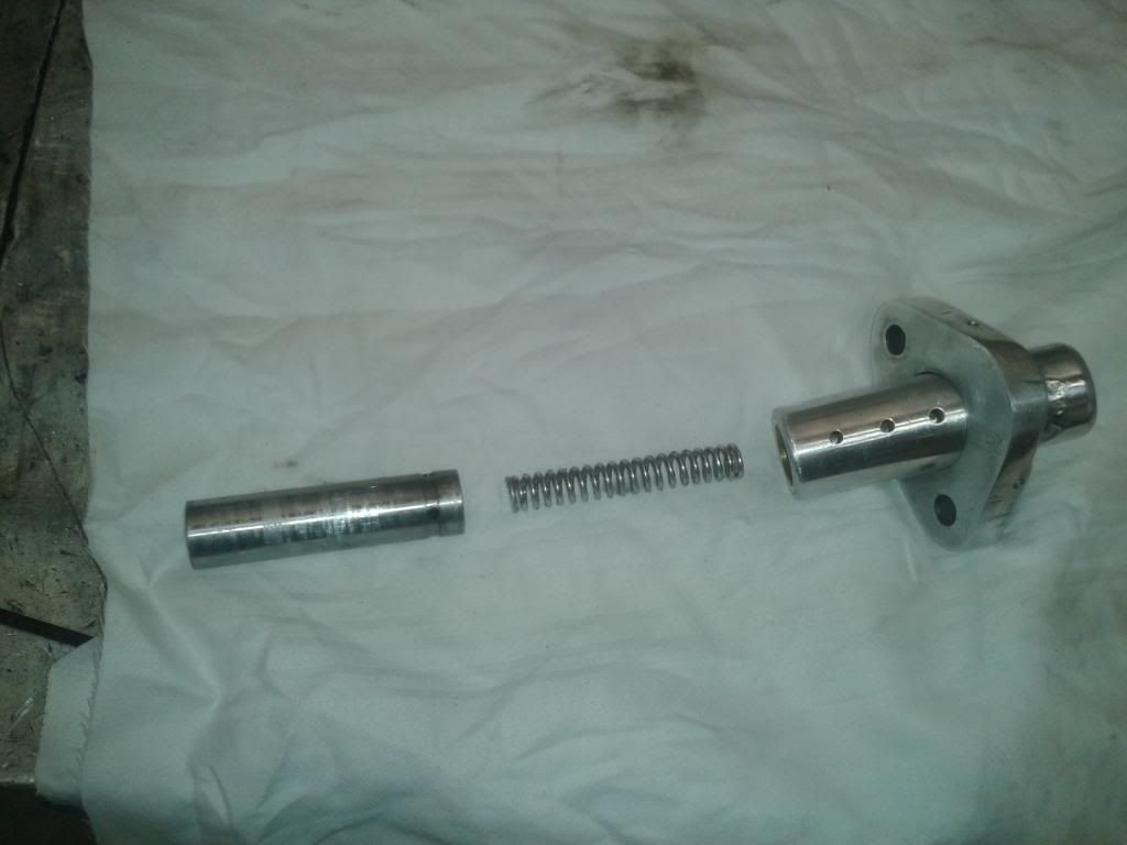
This was machined from solid, and contains the dual acting piston for shifting reverse. There is an interlock from the neutral lug on the selector drum for the neutral light. so you can't select reverse without the box being in true neutral, is basically the relay for the air solenoid can't ground without it.
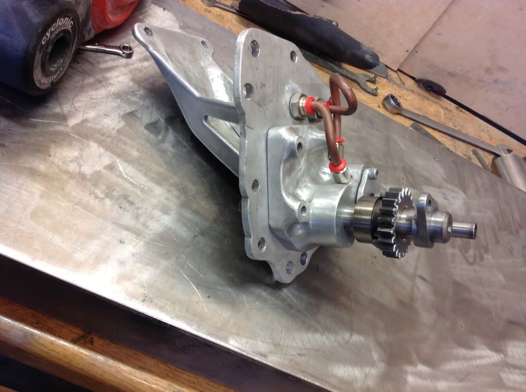
Internals for air piston.
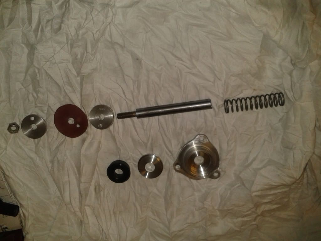
The air pressure is supplied up via an air pump (design stolen from the Bugatti air pumps), to a cylinder. The pump runs on the originals camshaft fuel pump lobe.
paulrandall said:
I regret selling my Mini on a regular basis.
Still hoping to get one again, but prices have recently gone crazy.
To think I picked up a pristine one in 2004 for £1,500.
The odd bargain is still out there, usually the unfinished projects are the best to buy. But ther are lots of rot boxes going for strong money too!Still hoping to get one again, but prices have recently gone crazy.
To think I picked up a pristine one in 2004 for £1,500.
guru_1071 said:
a lad at work had a screamer pipe stuck out the bonnet of his car
we carefully saved all the paper bits from out hole punches and filled it right up one day.
he got the shock of his life when it spewed them all out when he was giving it some.....

Haha, I put wire wool down the screamer at shows as I know it would be far too tempting for some people to drop something down there. we carefully saved all the paper bits from out hole punches and filled it right up one day.
he got the shock of his life when it spewed them all out when he was giving it some.....
A few more pics of the box.
Shifter mechanism.
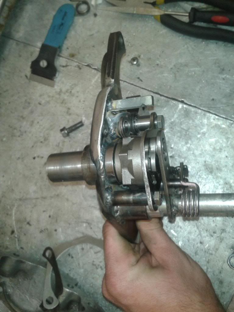
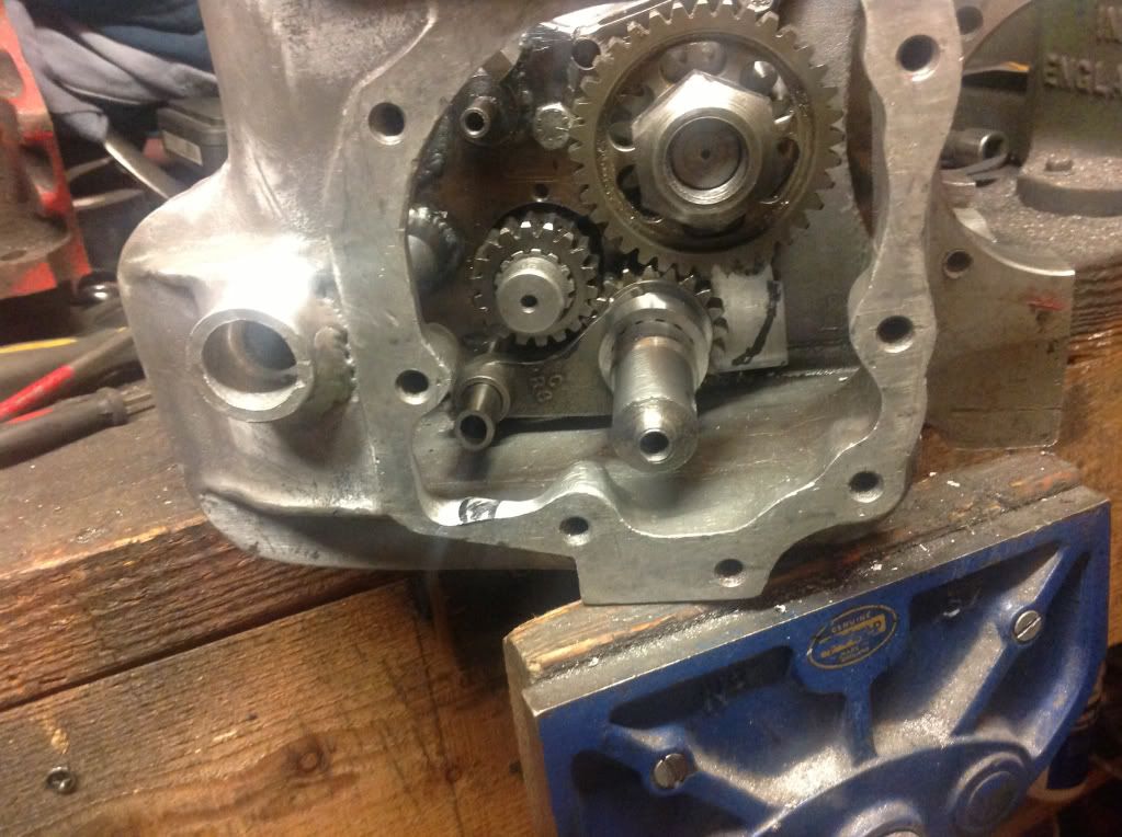
Additional idler gear I designed, that has a thrust face built in on the inside to run on the bronze bush.
It also has an additional drop gear on the 1st motion shaft, and a second support bearing on the transfer housing too.
I haven't got any finished pictures of this, but it gives an idea...
The shifter is translogic electronic linear actuator, so it can be shifted either on the wheel or via the gearstick, with 2 micro switches in place. I have it all wired into my ecu, so the ecu does the shift cut, and anti lag kicks in, so I should hopefully be able to flat shift without using the clutch to on up shifts...well that's the plan!
Shifter mechanism.
Additional idler gear I designed, that has a thrust face built in on the inside to run on the bronze bush.
It also has an additional drop gear on the 1st motion shaft, and a second support bearing on the transfer housing too.
I haven't got any finished pictures of this, but it gives an idea...
The shifter is translogic electronic linear actuator, so it can be shifted either on the wheel or via the gearstick, with 2 micro switches in place. I have it all wired into my ecu, so the ecu does the shift cut, and anti lag kicks in, so I should hopefully be able to flat shift without using the clutch to on up shifts...well that's the plan!
Gassing Station | Readers' Cars | Top of Page | What's New | My Stuff