Is this detonation damage?
Discussion


Some of you will have seen the recent unfortunate meltdown on my Rover k-series turbo that resulted in a melted piston ("stuballs BRM build thread"). I never really found a cause and whilst dropping the head and block off with my engine builder of choice for the rework today we cleaned the cyl head off and had a closer look.
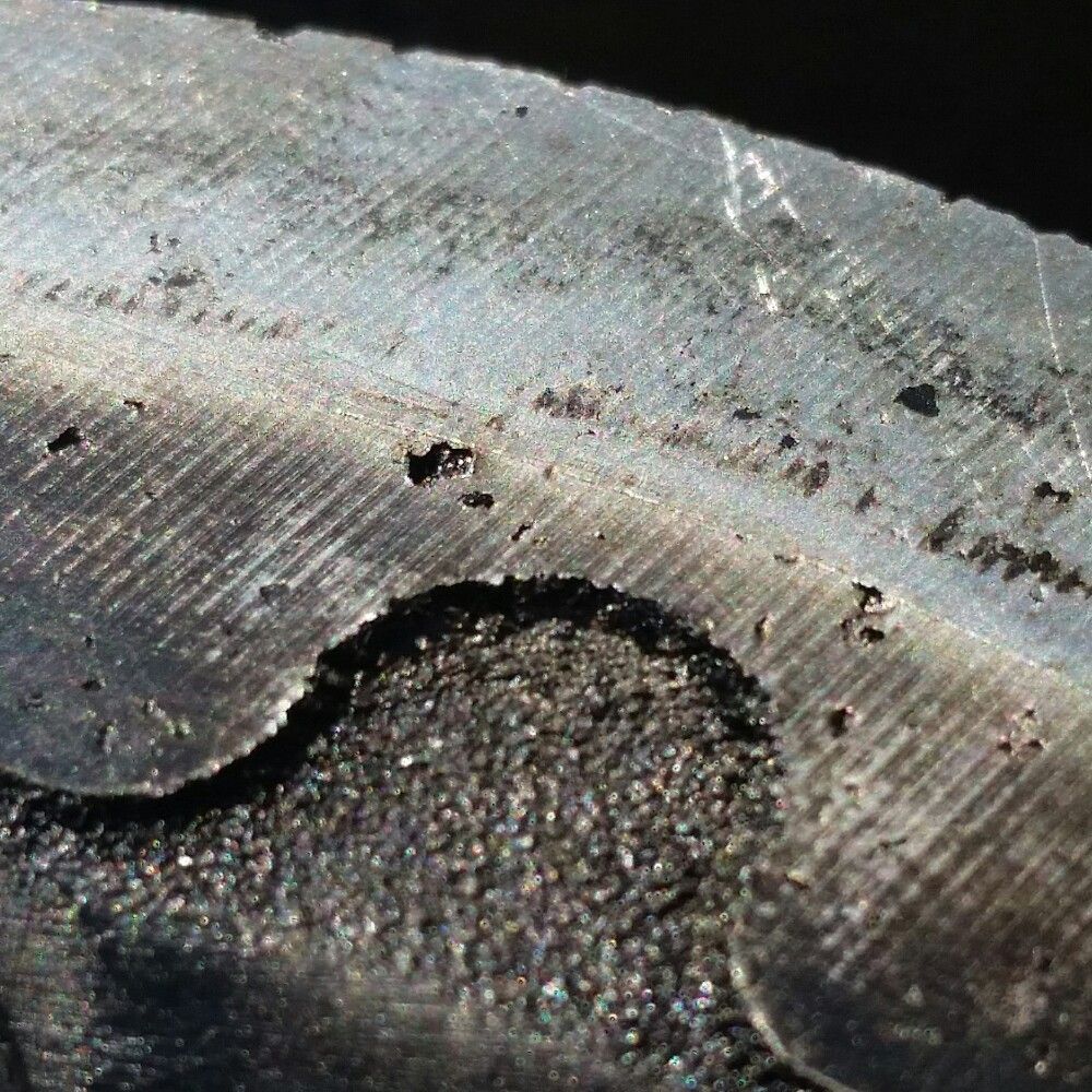
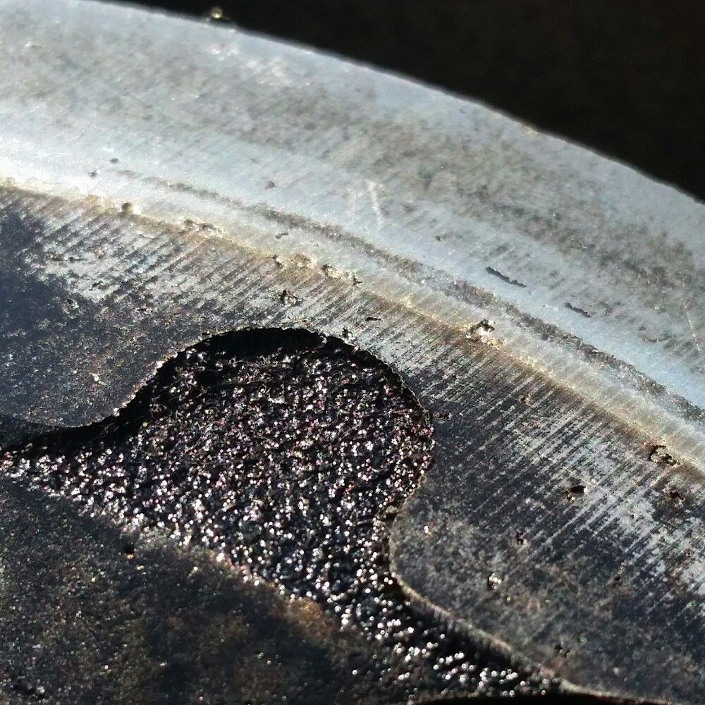
As you can see from the pictures below the cylinder head has some pitting on the squish pads - I didn't notice this before. Builder confirmed this is det damage and put it down to bad mapping. He thinks the failure is a combination of det and just weak pistons.
Thoughts?
As you can see from the pictures below the cylinder head has some pitting on the squish pads - I didn't notice this before. Builder confirmed this is det damage and put it down to bad mapping. He thinks the failure is a combination of det and just weak pistons.


Thoughts?
Thanks for the input guys. The markings outside of the fire rings are black residue from the resin (or whatever it is) of the mls head gasket. The pitting is definitely confined to within and near the fire rings and on the squish pads of the combustion chamber. Valves ok. Pistons all ok except for the one that melted and even that had no pitting anywhere.
I just thought I would get some other opinions before I went back to the mapper.
Thanks again.
I just thought I would get some other opinions before I went back to the mapper.
Thanks again.


stevieturbo said:
It almost looks like the valve cutout is cut right through to the top ring land ! Or very very very close to it.
And what were ring gaps like ?
Bang on with the excessive valve cutouts slicing almost into the top ring groove - several people have said the same thing including Scholar Engines. And what were ring gaps like ?
Ring gaps were at the wider end of what wossner recommended. I always worried I'd made them too wide as I had a fair bit of blow-by (breathed a lot of vapor though the catch can under boost). That said, cyl 1 had a lot of scoring. Maybe my feeler gauges are wrong?!
Boosted LS1 said:
OP, have you any pictures of the plugs, earth electrode?
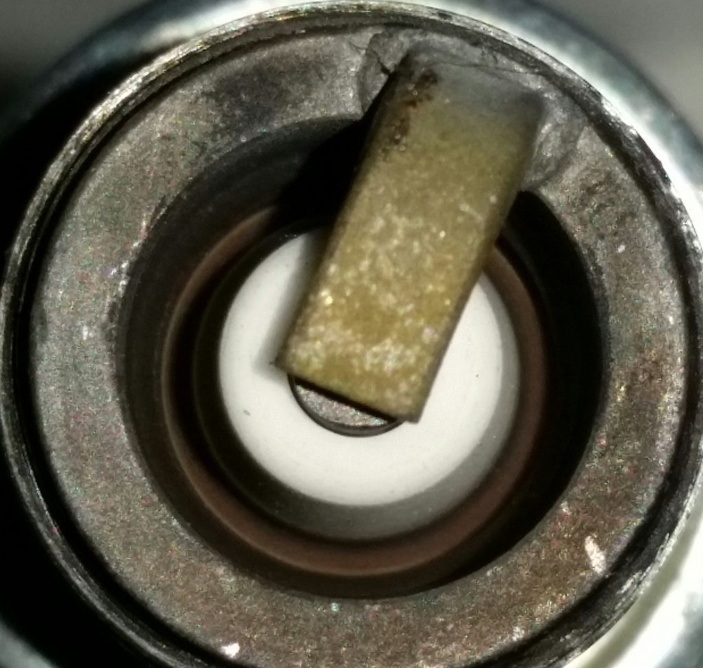
Only picture I have is the smashed in one from cyl 1 which doesn't show much. 
FordPrefect56 said:
It's very simple. If the cylinder head has det marks on the other three chambers where the piston didn't blow up then it's bad mapping that caused the det. If only the chamber where the piston blew up has det marks then the piston probably broke first from the valve cutouts failing.
All 4 cylinders have the same det marks. Not any worse on any one in particular. FordPrefect56 said:
It's what you don't know you don't know
Love that! Exactly the problem I've had coming at this as a novice. It's how you learn I suppose. But it's been an expensive lesson! Evoluzione said:
Creating a squish clearance as excessive as that ^^ would only make make the engine even more prone to det and that's on top of the fact that these newer items have lost the squish pads the old ones had.
And this is another piece of the puzzle - something I didn't know I didn't know. I used standard length nasp rods but used an n-series gasket which has 5 layers and compresses to 2mm. I did this partially to help lower compression. But in doing so I probably compromised the squish. Evoluzione said:
In the other thread the OP mentions fuel pump failure IIRC and also the mapper not listening for det.
Yes I still think the walbro in tank pump was part of the problem. Thanks everyone for taking the time to comment. It's been really helpful.
My belief is that this was a combination of one or more factors causing det (weak fuel system, bad squish, reversion from short exhaust runners, ring gap/clearance issue) and the fragile pistons dying at the first sign of a problem.
Boosted LS1 said:
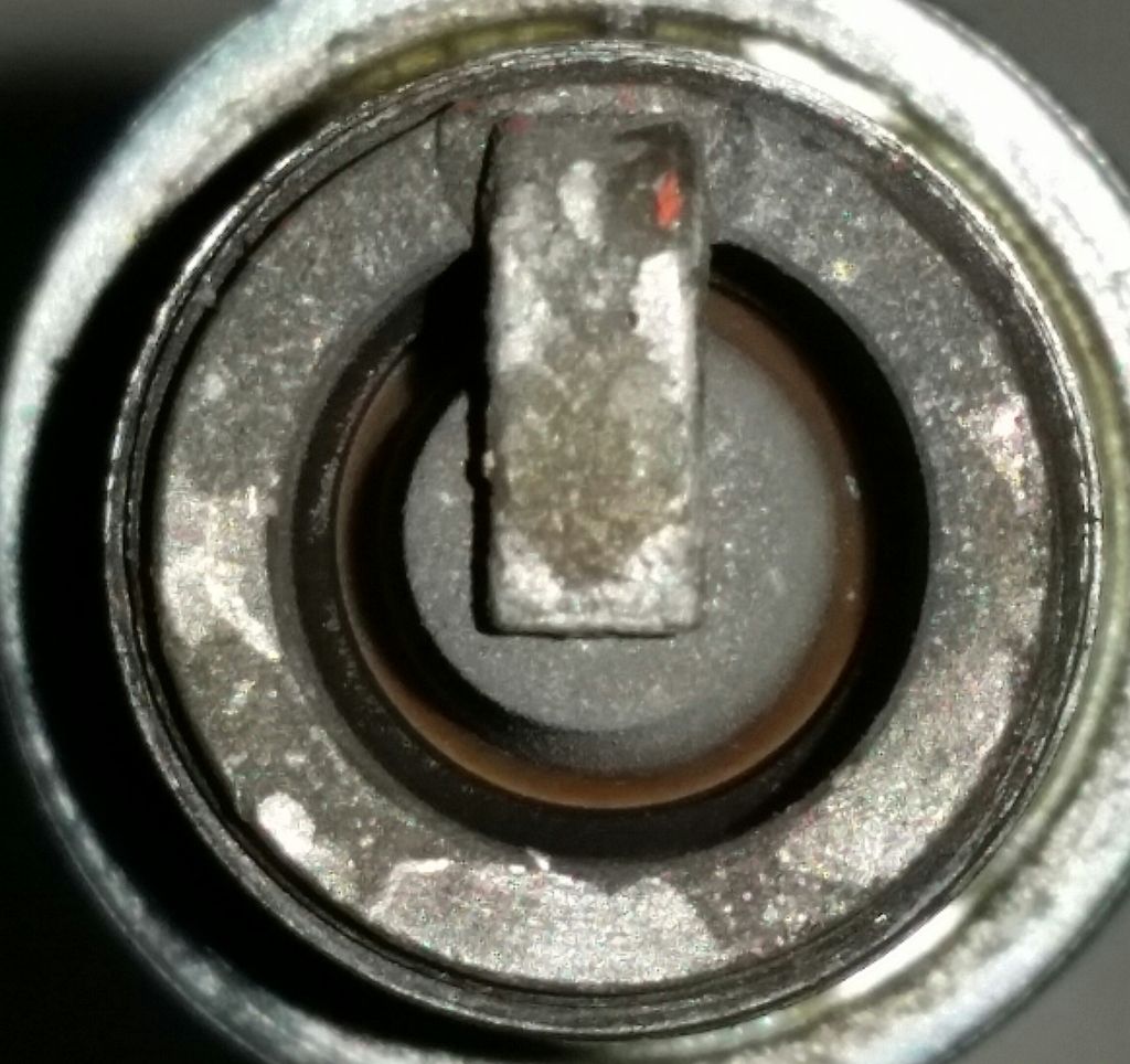
OP, can you post up pics of the other plugs? A pic showing a close up of the earth electrode from a side view, any side will do. Another pic looking down into the plug, preferably under decent lighting. It's the porcelain I want to see, deep down if possible.
ETA, have you a pic of the damaged plug, looking down on it?
Couldn't really get side-on pic as the insulator is recessed ETA, have you a pic of the damaged plug, looking down on it?
Plug from failed cylinder:

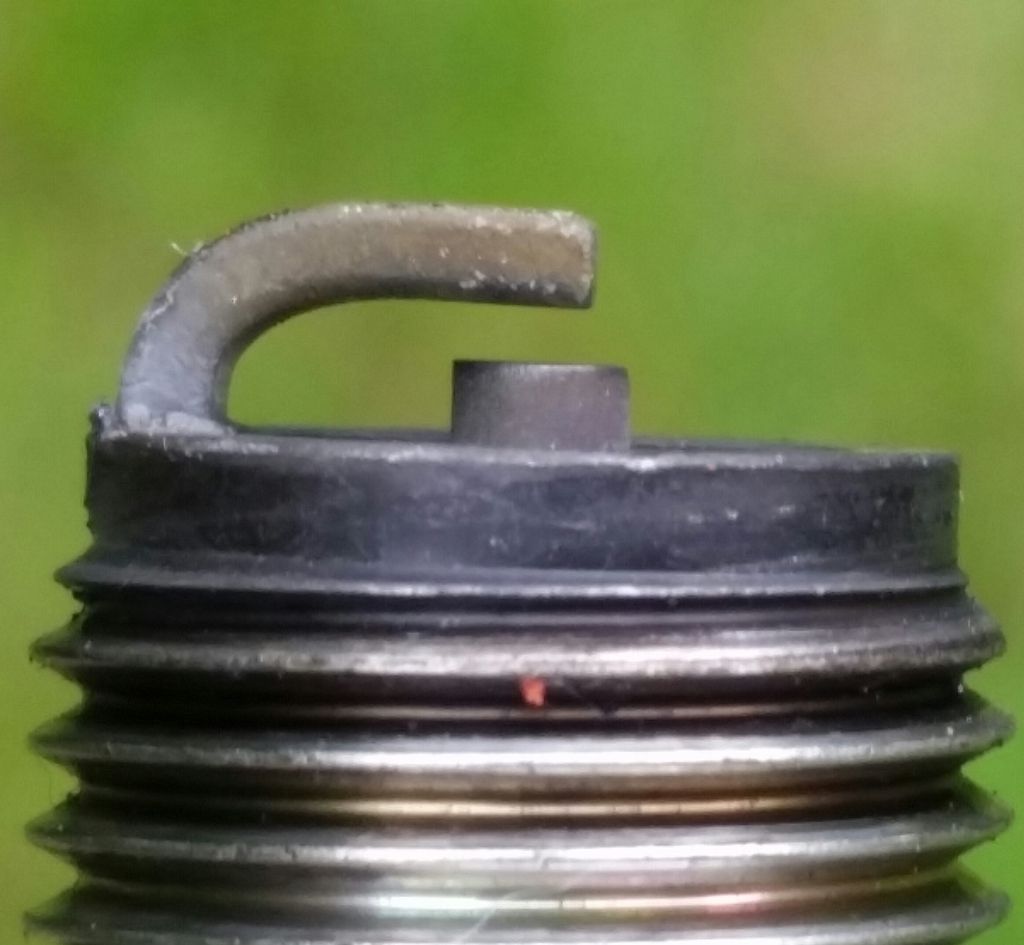
Cylinder 2:

stevieturbo said:
So what were the ring gaps ?
And no, lots of blowby will not be because of ring gaps...I doubt anyone could make them that big. But poor bore prep and ring sealing would cause a lot of blowby.
In what way did the fuel pump fail ? Walbros are usually very reliable and I doubt most K-series would ever trouble the typical in tank Walbro pump in terms of fuel supply ability.
Was fueling not being monitored ? fuel pressure ?
People rant about squish and other stuff, ffs years ago I just chopped the tops of pistons for a free turbo build and never had an issue. I've ran some 6-7mm down the bore !
If those huge valve cutouts really are needed, I'd sooner move the ring pack down the bore and run a piston with a more solid top than those pistons, even if it meant less of any shape to the crown.
As for reversion from short exhaust runners ??? WTF
Ring gaps 19 thou top. 17 thou middle.And no, lots of blowby will not be because of ring gaps...I doubt anyone could make them that big. But poor bore prep and ring sealing would cause a lot of blowby.
In what way did the fuel pump fail ? Walbros are usually very reliable and I doubt most K-series would ever trouble the typical in tank Walbro pump in terms of fuel supply ability.
Was fueling not being monitored ? fuel pressure ?
People rant about squish and other stuff, ffs years ago I just chopped the tops of pistons for a free turbo build and never had an issue. I've ran some 6-7mm down the bore !
If those huge valve cutouts really are needed, I'd sooner move the ring pack down the bore and run a piston with a more solid top than those pistons, even if it meant less of any shape to the crown.
As for reversion from short exhaust runners ??? WTF
Liners are from wossner. Ductile iron. I didn't do anything with them by way of prep.
Fuel pressure was being monitored. I can't put my finger on a particular issue otherwise I found happily say "yes it was the fuel". But it was not a straight swap for the standard pump and required fettling to get it to fit. Although it did eventually for and pesticide fuel. But the resultant fuel flow had a pulse to it that the stock pump didn't have. After the pump upgrade the fuel pressure had a slight flutter to it at idle, which the mapper said was normal.
stevieturbo said:
I've no idea on K-series etc...but these liners come fully prepped to just drop in and work with new pistons and rings ? No honing required or anything like that ?
They drop in with a bead of hylomar around the seat. They are held in place by the head (if you even then the crank with the head removed the liner can unseat. They come pre-honed, ready to go. That said, the guy at Scholar who looked at the pistons said he doesn't like the drop fit liners as they move and distort with heat. Theirs are pressed into the block after its been heated. So hopefully I never need to get them out!
Hi guys. Thanks again for all the replies. Sorry for not coming back sooner Had a mental week at work.
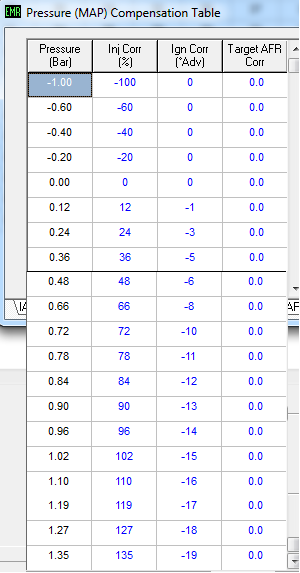
MAP compensation table:
Boosted LS1 said:
OP, plug 2 doesn't show if it was hot or not but I can't see far enough inside to check fueling. Can you get a picture that shows a fueling band/ring at the base of the insulator?
Can you show a picture side on of the earth electrode?
These are the best pics I can get:Can you show a picture side on of the earth electrode?
FordPrefect56 said:
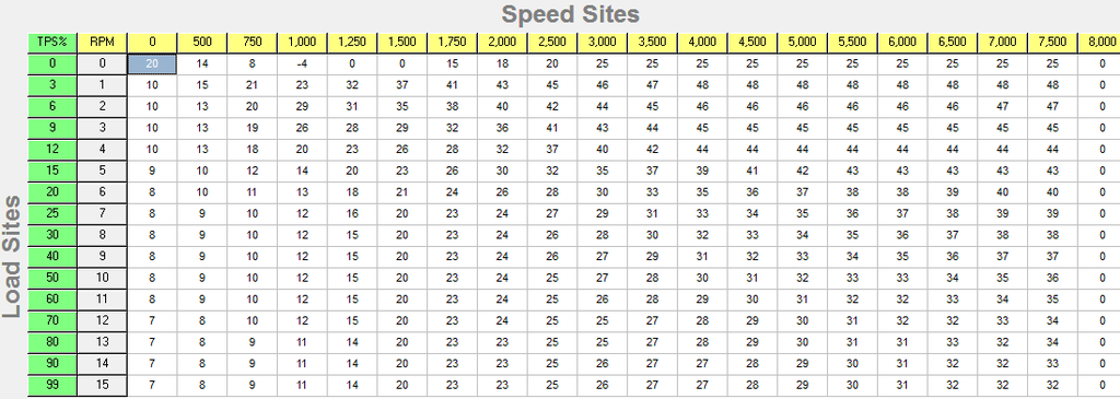
Maybe the OP can post his ignition maps including most importantly the boost retard values.
Ignition map:MAP compensation table:

AER said:
If you look closely you'll see areas outside the combustion chamber that look very much like porosity ready to open up.
Porosity did occur to me as a possibility as k-series heads are often known to expose porosity even with a light skim.FordPrefect56 said:
And to the OP. You've spent thousands of hours on this, mainly on the shiny bits, but taken it for mapping with a totally unsuitable ignition map. I have great sympathy but a chain is only as strong as its weakest link and for the sake of that last bit of learning and research this would still be running. You wondered why it wouldn't idle in your build thread. Have you figured that out yet?? It's a bit of a no brainer.
Finally the cracked valve spring cap you had. That looks very like what happens when the collets are non std and not the same included angle as the cap.
Sure I built it myself because I wanted to learn how to do that. But when it came to mapping I just had to place my trust in a mapper. I couldn't have done that myself. I researched a lot and the place I used had a great reputation. I had no choice but to give them the car and trust them to do it properly. Obviously I'm gutted with the outcome but it's easy for me to say with hindsight that I should have used a different mapper. I guess my mistake there was not knowing he should have been wearing det cans.Finally the cracked valve spring cap you had. That looks very like what happens when the collets are non std and not the same included angle as the cap.
Cracked valve spring cap was on completely stock standard VVC valve train.
So do people generally prefer MAP/RPM mapping? The first mapper did it that way and that was when i had the trouble with it idling.
Gassing Station | Engines & Drivetrain | Top of Page | What's New | My Stuff