Calling Max_Torque - manifolds and turbos question
Discussion


Hi All,
I'm hoping (as title) to attract some comment from Mr.Max_torque on a few questions I have, in my opinion it's not often you find someone with the skill and knowledge that Max has that openly gives comment and advice.
So, if you don't mind Max
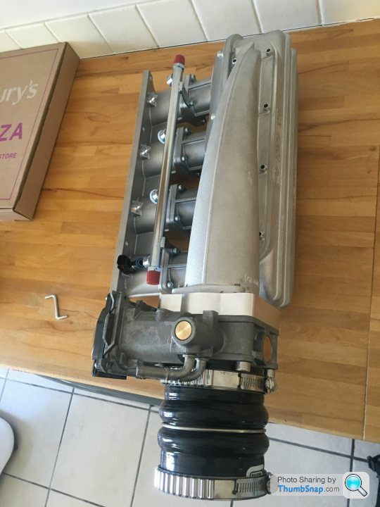
1. Inlet manifold design for a turbocharged engine, I notice your Seat has what appears to be a "dual plenum" inlet manifold with a smaller tapered plenum feeding a larger main plenum. I'm aiming to use a similar manifold on my project (a turbocharged Honda K24 block with K20 head), what is your opinion on the Jenvey Turbo plenum? It's the best option I can find "off the shelf" for my engine but the shape does not look optimal.
2. Any advice on inlet manifold runner length for the above?
3. I am trying to find information on designing the exhuast manilfold, many people I speak to say "doesn't matter on a turbocharged engine" which I disagree with. Can you help or give me some pointers on runner length, or some good reading on the subject? I will be designing this with good wastegate positioning as a priority, something that appears to be overlooked in 99% of after market manifolds.
Any reply, comment or suggestions much appreciated!
Thanks,
A
I'm hoping (as title) to attract some comment from Mr.Max_torque on a few questions I have, in my opinion it's not often you find someone with the skill and knowledge that Max has that openly gives comment and advice.
So, if you don't mind Max
1. Inlet manifold design for a turbocharged engine, I notice your Seat has what appears to be a "dual plenum" inlet manifold with a smaller tapered plenum feeding a larger main plenum. I'm aiming to use a similar manifold on my project (a turbocharged Honda K24 block with K20 head), what is your opinion on the Jenvey Turbo plenum? It's the best option I can find "off the shelf" for my engine but the shape does not look optimal.
2. Any advice on inlet manifold runner length for the above?
3. I am trying to find information on designing the exhuast manilfold, many people I speak to say "doesn't matter on a turbocharged engine" which I disagree with. Can you help or give me some pointers on runner length, or some good reading on the subject? I will be designing this with good wastegate positioning as a priority, something that appears to be overlooked in 99% of after market manifolds.
Any reply, comment or suggestions much appreciated!
Thanks,
A
stevieturbo said:
At a guess you're overthinking things. How much power are you aiming for ? Are you pushing extremes ?
If you're getting picky about exhaust manifold design..of course head design, intake, cam profiles, exhaust, turbo etc all then need to be factored in as a package.
What is the engine used for, over what rpm range etc etc
As for saying wastegate position is overlooked.....no doubt it is placed where it is practical given physical constraints...and you can be fairly sure in 98% of cases it works perfectly fine. So in many respects it is the least of the worries
IMO, keep it simple its a doddle to make power with a turbo engine.
I dont think I'm over thinking anything, I want to make the best possible power / get the best result, but most of all LEARN from the experience so I understand the result I get.If you're getting picky about exhaust manifold design..of course head design, intake, cam profiles, exhaust, turbo etc all then need to be factored in as a package.
What is the engine used for, over what rpm range etc etc
As for saying wastegate position is overlooked.....no doubt it is placed where it is practical given physical constraints...and you can be fairly sure in 98% of cases it works perfectly fine. So in many respects it is the least of the worries
IMO, keep it simple its a doddle to make power with a turbo engine.
Edited by stevieturbo on Monday 25th July 11:44
Aiming for... ~500+whp (so not record breaking, but still a good 200bhp+ per liter), engine will be used in a Lotus Elise/Exige chassis for track work, with a Quaife sequential, rev limit of ~8000rpm (piston speeds taken into account).
I am lucky as I am not too constrained in packaging of the exhaust manifold - plenty of room for optimised length and construction - so I am looking for guidance on choosing / designing the optimal solution.
Edited by sl0wlane on Monday 25th July 14:49
Ive said:
the reason a side entry plenum for a forced induction inline 4 engine is tapered is to maintain a constant air velocity across all four cylinders.
As each cylinder takes its breath, the air mass is reduced by 25%. To maintain air speed and with it pressure equal across all cylinders, the cross section reduces by 25% over each cylinder. Cyl 1 100%, Cyl 2 75%, 3 50%, 4 25%. For a Na engine, this effect is much less pronounced, hence NA a plenum often uses a uniform cross section.
The dual plenum designs work in a similar manner. The small inlet plenum tapered as above. It is connected to the main plenum with a longitudinal slit across the entire length of the tapered part.. Due to providing uniform pressure and velocity across the slit, the bigger secondary plenum is filled uniformly across all cylinders through that slit The larger total volume of the uniform plenum helps reducing pressure fluctuations thereby increasing air flow.
Here are some examples and a useful discussion:
http://www.k20a.org/forum/showthread.php?t=90664
Thanks Ive - and yes, fully understand the function of the "dual" plenum - notice my post is the last on the thread you linked As each cylinder takes its breath, the air mass is reduced by 25%. To maintain air speed and with it pressure equal across all cylinders, the cross section reduces by 25% over each cylinder. Cyl 1 100%, Cyl 2 75%, 3 50%, 4 25%. For a Na engine, this effect is much less pronounced, hence NA a plenum often uses a uniform cross section.
The dual plenum designs work in a similar manner. The small inlet plenum tapered as above. It is connected to the main plenum with a longitudinal slit across the entire length of the tapered part.. Due to providing uniform pressure and velocity across the slit, the bigger secondary plenum is filled uniformly across all cylinders through that slit The larger total volume of the uniform plenum helps reducing pressure fluctuations thereby increasing air flow.
Here are some examples and a useful discussion:
http://www.k20a.org/forum/showthread.php?t=90664
Ive said:
The length and cross section of the intake runners primarily determine the range of peak torque. The length is primarily acting through acoustic resonance. The cross section is more modulating air velocity.
Small cross sections provide high air velocity at low rpm lowering the rpm of peak torque.
Long runners resonate at low frequencies, shorter at high frequencies.
When it comes to forced induction, the same acoustic principles apply. What makes life easy is that the speed of sound does not change much with air pressure. As pressure increases, the density increase would increase speed of sound, but the increased air mass reduces it again. So for the sake of the accuracy empirical formulas used to calculate plenum runner length and cars section, you can treat speed of sound as constant or can ignore the pressure.
Thanks - I can apply this and compare my runner length to the results from others.Small cross sections provide high air velocity at low rpm lowering the rpm of peak torque.
Long runners resonate at low frequencies, shorter at high frequencies.
When it comes to forced induction, the same acoustic principles apply. What makes life easy is that the speed of sound does not change much with air pressure. As pressure increases, the density increase would increase speed of sound, but the increased air mass reduces it again. So for the sake of the accuracy empirical formulas used to calculate plenum runner length and cars section, you can treat speed of sound as constant or can ignore the pressure.
I'm aiming for a usable powerband 4000rpm through 8000rpm
Edited by sl0wlane on Monday 25th July 15:30
Edited by sl0wlane on Monday 25th July 15:30
Well I have found a few more resources online, looks like I need further info on the cam spec... Which I have most of but cam centre line is proving harder to pin down... as its a VTEC engine and also fitted with an adjustable exhaust pulley...
Anyone got a really good model of a turbo K20 in GTSuite they don't mind sharing? (unlikely, I understand it takes months to build an accurate model).
Anyone got a really good model of a turbo K20 in GTSuite they don't mind sharing?
(unlikely, I understand it takes months to build an accurate model).There is but only on Seloc... I might copy over here too at some point (Seloc being locked out for even viewing unless registered is a bit of a pain).
A basic run down of the spec sheet:
Clockwise Motion Darton sleeved K24 87x99mm block
K20a head (ported exhaust ports, standard intake).
Inconel exhaust valves
K20 oil pump etc (standard k20/24 frank setup)
Clockwise "turbo" cams and adjustable exhaust pulley
Clockwise forged steel con rods
CP 9.5:1 forged pistons
L19 head studs
Clockwise ultralight flywheel & twin plate clutch
Clockwise baffled sump
Clockwise water pump delete and lightweight alternator kit (will use the BMW cWA200 electric pump)
Laminova oil cooler (the biggest one)
Jenvey turbo plenum and inlet manifold
70mm flybywire throttle body
ID1000 injectors
DW 300 fuel pump
DW fuel pressure regulator
TiAL 44 mvr wastegate
Owen developments ODGT3579HTA M-spec turbo
Quaife sequential box with LSD
ECU is a an EFI Euro4 from Ole Buhl, which has traction control, closed loop boost, ETB control, closed loop flat shift, closed loop fuel etc etc etc
The project is with Dan Webster at HPE
Still working out how to do intercooling and exhaust (no, I'm not doing a charge-cooler! I'm going air-air)
Umm that's about all the relivent bits I think.
Edited by sl0wlane on Thursday 18th August 23:34
Edited by sl0wlane on Thursday 18th August 23:37
I have Lee, and I'm eagerly waiting to see your results... Hopefully you can do some proper data logging of inlet and outlet temps on the intercooler so we can see the delta.
I might not be able to do the same as, unlike your car, I will have a hot manifold and turbo right in front of the intercooler if I use that position, being that the K20 has the exhaust ports on the either side of the head to the Rover as you know.
I'm waiting for Concept Racing to open (appears they close and go on holidays for August)... Then I'll talk to them about manifold and intercooler design and placement to see if they can help (http://www.conceptracing.co.uk)
Ive said:
in general a plenum should have a certain minimum volume that is usually a multiple of each cylinders displacement.
I remeber it being like 10x to avoid power losses from pressure drop in the chamber as the intake stroke happens.
so for a 2.4l your want some 6 liters inthe ideal world. in reality you get away with much less before significan losses occur.
My old KTM Duke 2nd edition came with a tiny airbox from the factory. 609cc single attached to a like 2l airbox is no good. Increasing plenum volume to infinite by fitting a open air filter. no other changes than a bigger mainjet released plenty of top end power.
The length is entirely dependent of the rpm band. I have sned you the spread sheet with some empirical fomulas in it.
you need cross section and lengh from mouth to intake valve. Then check where the 2nd, 3rd and 4th harmonics are.
if you strive for 7000 rpm peak torque, you want your effective lengh tuned to the 2nd or 3rd harmonic at that rpm. 1st would even be better, but I doubt you can and want to fit such long snorkel to your engine.
My old plastic plenum on my supercharged K would really pick up again past 7800 rpm. This fitted to the 4th harmonic of this geometry. In between 5000 rpm of the 3rd harmonic peak and the 7800 of the 4th there is the "valley of death". here the refelcting sound waves actually reduce the pressure at the port during the intake stroke. You could feel it and see it from the fuel values to maintain AFR and from the ignition timing I could add before knock. VE was dropping.
The shorter VVC plenum shifts things upward, so I am less affected by the drop past the 3rd harmonic peak. Still, past 7000, power does not rise anymore as VE drops.
If I would fit ITBs with shorter runners than the VVC plenum, VE would drastically increase at high revs. This can be seen from dyno data. otherwise identical spec NA engines,m even the same cam timing, generate some 160HP on a plenum at 7000 and some 180HP on ITBs.
have you calculated the peak rpms for your intake set-up? what length is the intake path from mouth to intake valve? What is the (average if conical) cross section?
The only reason the Honda k20 engines get away with such a short plenum regarding the low and mid rpm torque is their reduced cam timing and lift to help VE in those load and rpm ranges. At the top they need the short wide runners to be able fill the cylinders effecitvely.
if you check some online articles comapring various plenums on K20 engines with dyno charts, you can nicely see the influence of the length of torque and power. as this influence is large pressure independent, you can orient yourself on thos lenghts regardng your intended torque curve.
Thanks Ive, most helpful! The good thing about the Jenvey manifold is that I can change the length very easily by changing the spacers (currently 50mm long), from your info above it looks like shorter might be better (I had not taken into account the VTEC at lower RPM).I remeber it being like 10x to avoid power losses from pressure drop in the chamber as the intake stroke happens.
so for a 2.4l your want some 6 liters inthe ideal world. in reality you get away with much less before significan losses occur.
My old KTM Duke 2nd edition came with a tiny airbox from the factory. 609cc single attached to a like 2l airbox is no good. Increasing plenum volume to infinite by fitting a open air filter. no other changes than a bigger mainjet released plenty of top end power.
The length is entirely dependent of the rpm band. I have sned you the spread sheet with some empirical fomulas in it.
you need cross section and lengh from mouth to intake valve. Then check where the 2nd, 3rd and 4th harmonics are.
if you strive for 7000 rpm peak torque, you want your effective lengh tuned to the 2nd or 3rd harmonic at that rpm. 1st would even be better, but I doubt you can and want to fit such long snorkel to your engine.
My old plastic plenum on my supercharged K would really pick up again past 7800 rpm. This fitted to the 4th harmonic of this geometry. In between 5000 rpm of the 3rd harmonic peak and the 7800 of the 4th there is the "valley of death". here the refelcting sound waves actually reduce the pressure at the port during the intake stroke. You could feel it and see it from the fuel values to maintain AFR and from the ignition timing I could add before knock. VE was dropping.
The shorter VVC plenum shifts things upward, so I am less affected by the drop past the 3rd harmonic peak. Still, past 7000, power does not rise anymore as VE drops.
If I would fit ITBs with shorter runners than the VVC plenum, VE would drastically increase at high revs. This can be seen from dyno data. otherwise identical spec NA engines,m even the same cam timing, generate some 160HP on a plenum at 7000 and some 180HP on ITBs.
have you calculated the peak rpms for your intake set-up? what length is the intake path from mouth to intake valve? What is the (average if conical) cross section?
The only reason the Honda k20 engines get away with such a short plenum regarding the low and mid rpm torque is their reduced cam timing and lift to help VE in those load and rpm ranges. At the top they need the short wide runners to be able fill the cylinders effecitvely.
if you check some online articles comapring various plenums on K20 engines with dyno charts, you can nicely see the influence of the length of torque and power. as this influence is large pressure independent, you can orient yourself on thos lenghts regardng your intended torque curve.
Edited by Ive on Friday 19th August 12:18
I need to measure the manifold but also the length of the ports to the valves in the head to get a handle on this fully.
Another question... What RPM should I target?! So far I have been working on 6000rpm, as this is right in the middle of the power band, but I guess on a pure race car you would target perhaps higher ~7000rpm (I guess then it comes down to the gearbox ratios as well).... Such an interesting and multifaceted subject!
Gunt said:
Hi , New here but i said i'd just chime in
Thanks for posting Gunt said:
i see what you are trying to achieve but you are watching the wrong details way with too much emphasis , those twin plane plenums are always only ever used on engines where restrictor's are required WRC etc and or to get around a serious original design issue , ie where there is a retro fit to a section of original two piece manifold .
Hmm, I agree a good portion of them have inlet restrictors... But some don't, including I believe the current BTCC cars (which are boost limited but do not run a restrictor as far as I can see)... Another example is Max_Torques car, which I don think has a restrictor either - hence asking him to comment.Gunt said:
watching all the guys who achieve serious out puts they are hovering around 2.5 time the engines cc for manifold volume .
if you have ever seen a proper n/a turbo conversion , you can take the n/a value and add 1 bar .The new charged out put is exactly double as its atmospheric value has now just doubled [ on a well designed set up ]
I agree, but I'll put it to you that this is the result of having a good EMAP vs IMAP ratio, e.g getting on for 1:1, rather than most turbo cars, including factory cars that are more like 2:1 or worse (certainly worse if running higher boost than original design intended).if you have ever seen a proper n/a turbo conversion , you can take the n/a value and add 1 bar .The new charged out put is exactly double as its atmospheric value has now just doubled [ on a well designed set up ]
Gunt said:
you are asking the question and trying to guess where you want peek tq , this is a honda I V-tec motor there should be no peek , say bar a few where spool comes on until spikes are full controlled , to me you should be looking at the near perfect n/a graph dropping compression , optimizing a turbo reasonably long 4 branch twin waste gate would help [ not needed on a honda ] you should see a 4-5k power band peek tq to bhp even at 700 so 5-600 bhp will be no problem
We have ended up going for around 24-27" equal length, wastegate priority manifold, constrained by the packaging in the car... I have hopes of the final figures starting with a 5 or if really lucky a 6 Gunt said:
my biggest question is what fuel are you aiming to use as this will dictate more than the rest , putting this power through 2 wheels , you wont want peek tq just linear progression always predictable
Fuel is going to be pump "super", this will be a road going car, I don't want to be limited to fancy fuel. As such I can't see it would be wise to go any further than around 22psi, maybe a touch further but will need to see what the knock threshold looks like once we are into mapping.Also totally agree, I want a nice progressive power curve, so I have an electronic throttle, boost by gear and throttle input and traction control to help with that... I also have a sequential box, so keeping it in the power band should be easier (if a little scary).
Wheel spin will no doubt be a problem...
Dummy engine going in the car and fabrication of the manifold, intercooler and various plumbing starts on the 17th

Just a bump in the slim hope Mr.Max_Torque sees this and takes pity on me
I'm just down to exhaust manifold runner length, the inlet runners are easily adjustable later, but fabricated Inconel exhaust headers not quite so...
Any help would be really really appreciated! I honestly google the hell out of us every night (and have done for months and months) and still don't have a satisfactory formula for determining the exhaust manifold dimensions... inlet theory and N/A exhaust theory quite easy to find and apply... perhaps I just use the same calculations?
Pretty please with a cherry on top
Edited by sl0wlane on Wednesday 30th November 07:04
stevieturbo said:
Given crappy cast manifold designs spool fast and make good power.....really, dont worry about it too much. Even worse log manifolds also work
So what sort of extreme are you working to ? How much space do you have to create a fancy design ?
And really...there are bound to be thousands of similar size engines making similar power goals to use as a model. There will be no re-inventing the wheel here, anything you want done you can be sure has already been done many times both cheaply and very expensive. How much difference between the two in terms of performance ? Probably not a huge amount in a lot of cases.
the 500hp power goal is quite modest. So keep tube sizes on the smaller size, if you can go twin scroll and if you can equal length all good too.. But really....if you could not make 500hp these days, something is wrong.
"Optimising" lengths etc....would surely involve head flow details, camshaft details and other factors and probably lots of either simulations or dyno testing. If that isnt within your budget for your particular setup, dont get too worried about it.
Thanks for the comments but you are missing the point somewhat old bean.So what sort of extreme are you working to ? How much space do you have to create a fancy design ?
And really...there are bound to be thousands of similar size engines making similar power goals to use as a model. There will be no re-inventing the wheel here, anything you want done you can be sure has already been done many times both cheaply and very expensive. How much difference between the two in terms of performance ? Probably not a huge amount in a lot of cases.
the 500hp power goal is quite modest. So keep tube sizes on the smaller size, if you can go twin scroll and if you can equal length all good too.. But really....if you could not make 500hp these days, something is wrong.
"Optimising" lengths etc....would surely involve head flow details, camshaft details and other factors and probably lots of either simulations or dyno testing. If that isnt within your budget for your particular setup, dont get too worried about it.
I have an opportunity to firstly learn, secondly build a properly optimised system, I'm not trying to throw this together.
The fact that I'm having it fabricated in Inconel could also maybe indicate that I'm not looking for the cheapest / easiest option.
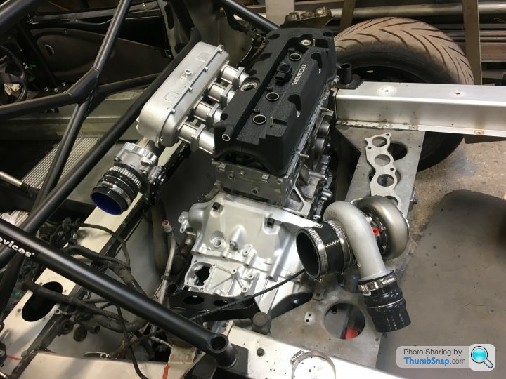
If you look at the above photo you can see I have plenty of space for pretty much any design size / length required.
I'm asking because I want to understand the science and be able to try my hand at designing the best possible solution.
The calculations do indeed require a number of inputs you mentioned and more, but if designed correctly and as close as I can to ideal it avoids many iterations of design / build / dyno... so surely doing the theory, if I can and have the opportunity makes sense?
227bhp said:
I think we're going round in circles here, all the salient points have already been mentioned.
One thing I haven't spotted though, what fuel are you going to use?
The points have been covered, but not by Max... One thing I haven't spotted though, what fuel are you going to use?

Fuel... initially just "pump" super / 99, 1000cc Injectors should hopefully be big enough for initial power goal... but I'm eyeing up a secondary fuel rail for the plenum for methanol injection later on perhaps.
Many thanks for th detailed and interesting reply
So, sorry, going back to length for my initial stab at it, a starting point if you will... and as you say probably only worth ~5% but regardless, I'm interested in the theory...
If I'm aiming for a compromise and if I take the lengths used by the NA builds for this engine that are known to work well (27" manifold primaries for example)... where should I start? The shortest possible is probably around 12" of equal length... I was aiming for around 24" inclusive of merge collector, does that sound around right for a first attempt?
I am aiming to log as much as possible, so far I have built into the design & will log:
1. Inlet manifold map sensor
2. Exhaust manifold map sensor (on coiled stainless pipe)
3. Pre turbine EGT sensor (single)
4. Post turbine Lambda
7. Compressor outlet air temp sensor
8. Inlet manifold air temp sensor
9. Inlet manifold air pressure sensor
So it sounds like I need to add an additional:
1. Pre compressor temp sensor (to log and understand compressor efficiency)
2. Post compressor pressure sensor
3. Wastegate pressure sensor (just a normal map sensor I'm assuming?)
Sadly my compressor cover does not have a boss for a compressor / shaft speed sensor like the new Borg Warner EFR turbos, so while I could have mine machined I'll probably not be able to log at this stage, similarly I don't think my wastegate has a position sensor option like some of the new breed... I could add post turbine pressure and temperature easily enough but I'm not sure I have any inputs left for logging / recording...
The manifold pipe size is just about the same as the exhaust port area, we can flare it at the manifold flange to create the anti reversion step and taper at 3 degrees back to the same area - thanks for this tip!!
I am using an electronic throttle so will hopefully be able to take into account your advice depending on what options / control my ECU allows.
I'm chassis logging, while I would dearly love to engine dyno it will add significant time to the project... and while I do want to make the best possible stab at it, I also would like to drive it at some point in the coming year
Thanks again... lots to think about!
Edited by sl0wlane on Sunday 4th December 10:18
stevieturbo said:
I would be very surprised if 27" is an ideal tuned length for every single engine of that kind....for every single head/intake combination, every single camshaft choice and not even a mention of tube diameter, nor desired operating rpm range for each particular engine.
Absolutely, this length is often used on the high revving ~300bhp 2.2NA builds - I have no idea on the camshaft spec of those, but you are correct, on reflection this will be nothing like my requirement... still, I am looking for a starting point!stevieturbo said:
You could go overboard logging some stuff and it sounds like your ecu has some limitations there ?
The ECU has:4 inductive or Hall effect engine speed and synchronization sensor inputs
4 Hall effect wheel speed sensors
3 spare Hall effect / digital switch inputs
2 knock sensor inputs
8 spare analogue sensor inputs via CAN
1 direct NTK UEGO lambda sensor input
20 analogue 0..5 Volts external sensor inputs (can also be used as switch inputs)
1 built-in barometric air pressure sensor
I need to add up everything I already have, perhaps I do have enough inputs.
stevieturbo said:
Really...if you have issues between post compressor and intake....you should have built a more efficient charge cooler/plumbing. Which would have been a major cost cutting exercise when you're worried so much about the exhaust manifold. Spending the money on areas like that and not being so concerned about the exhaust, would perhaps be better.
I haven't built the inter-cooler yet ?!?stevieturbo said:
Given the space you seem to have, it would be incredibly difficult to build a bad exhaust manifold.
You could log post turbine pressure...but again, why would you build an exhaust that is restrictive in the first place to actually need to log this ? Unless perhaps there are huge noise restrictions you need to abide by.
I have requested a 3.5" down-pipe from the turbine exit, through to the back box - should be very little restriction. The waste-gate will be entirely divorced and have its own tail pipe.You could log post turbine pressure...but again, why would you build an exhaust that is restrictive in the first place to actually need to log this ? Unless perhaps there are huge noise restrictions you need to abide by.
Edited by sl0wlane on Monday 5th December 11:23
Max_Torque said:
IME, a basic 1d iterative "simulation" in something like excel gets you 85 to 90% of the way there! And, when you have logged the actual parameters from the vehicle, you can then re-correlate your simulation, or at least change the values of things like exhaust length and see what effect they have.
It's pretty simple really, if you want the "Best" engine, you're going to have to do the math. If you are happy for a decent but, un-spectacular performance then just guessing and following what others have done will work ;-)
Thank you Max, and my point exactly - I would like to have a good stab at the math to bring me to a good first "prototype" I can then measure and see how far off I am or what changes could be made to improve - but I need to calculate a starting point initially.It's pretty simple really, if you want the "Best" engine, you're going to have to do the math. If you are happy for a decent but, un-spectacular performance then just guessing and following what others have done will work ;-)
I am trying to understand the science, not just copy something I could buy off the shelf and settle for "OK"
Gassing Station | Engines & Drivetrain | Top of Page | What's New | My Stuff