V12 breathers revisited.
Discussion


After reading a number of posts on here referencing the oil contamination of the air filters and inlet manifolds on the V12 engine, and the various methods of explaining and fixing it, I decided to take a good hard look at the problem and trying to solve it once and forever.
I took note that whilst replacing all the hoses and valves concerned with the engine breathers seemed to rectify the fault, this was only a temporary measure, and whilst our cars generally do not do normal mileages, a full rebuild every 30,000 miles or so on the engine breather system indicated an inherant fault in the design.
If the aforementioned parts were an easy and cheap fix, then a more involved modification would be unnecessary, but with the requirement to remove the inlet manifolds to access the parts, and parts and labour going in at over £600.00, I decided to try a more lasting solution.
I firstly needed to understand how it all worked, and why the problem exists in the outset. Using this diagram as a reference, I will try and explain how the system works.
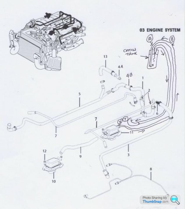
Hoses, part 7, are installed on the throttle bodies, downstream of the throttle plates, so at almost all times, these apply a vacuum to the top of two PCV (Positive Crankcase Ventilation) valves shown at position 2. This applied vacuum on the valves applies a regulated/balanced vacuum to the two oil separators via a “Y” connector and a pipe between positions “X” and “Y” to the rear oil separator, indicated at 11. This is connected directly to the front oil separator (10) by a pipe between them and causes a vacuum condition in the engine assembly.
So that there is not an excessive vacuum held in the crankcase, there are two pipes, “3” and “5” that allow fresh, metered volume of air to flow from the air intake, before the throttle body but after the airflow meters so that there is a constant fresh air flow through the engine case. This explains the name of the system as there is a positive flow of fresh air entering the crankcase, picking up any blowby gasses and oil vapours, and being reburnt through combustion by entering the inlet system.
Where the pipes allow fresh air to enter the engine through the camshaft covers, there is a one-way airflow valve at 4A and 6, known as “duck” valves so that air can enter the camcovers, but not blow out. The duck valves are known to fail, allowing oil vapour to flow back through the air “make-up” pipe and into the intakes, pre throttle.
The “duck” valves are so called because of their resemblance to a ducks bill where air flowing one way pushes the halves of the bill together but air from behind can flow easily.
HOWEVER, this system relies on engine intake vacuum to operate, which is greatest at small throttle openings. At high or full throttle, there is far less vacuum, and under these conditions, the increased blowby gases, build pressure in the crankcase, and this pressure is released through a further duck valve at position 4B where it travels in the opposite direction to the make-up air, and blows into the right hand side intake as well as through the two vacuum pipes.
If everything is working correctly, and the valves and separators are doing their job, there still seems to be an excess of oil vapour escaping into the intakes, usually at large and full throttle when the vacuum is low.
The ONLY place this oil laden vapour can flow is from the two separators into the “Y” connector through the pipe connection at “X-Y”.
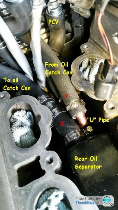
I have decided to intercept this vapour at that point and install a proper oil separator/catch can by splicing into that pipe and running the oil laden vapours into an easily cleaned, condensating container, therefore keeping the high acid/fuel laden oil vapour away from the inlets, protecting both the air filters, the throttle plates and engine from ingesting it.
I decided to purchase a cheap oil catch tank to save time but upon opening it up, it was clear to me that it was pretty useless as it was so I went about modifying it as follows.
The empty chamber started out with just two connectors in the lid and a sight glass. There was nothing inside to encourage the oil vapour to condense and separate out and I could see that the vapour would simply go in one pipe and straight out of the other.
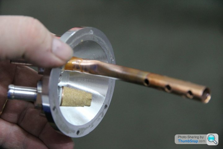
Firstly, I added a copper pipe, cross drilled into the inlet pipe aand to filter the air exiting the tank, I installed a small bronze compressor filter to the outlet fitting.

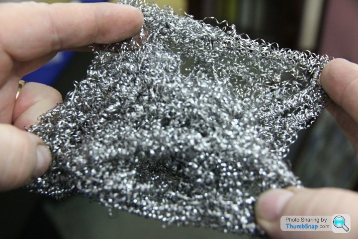
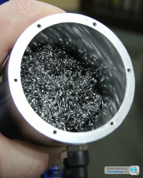
To force the vapours to the middle/lower end of the tank, I then added some stainless steel pan scourers into the bottom of the tank to separate the oil from the vapour.
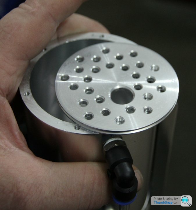
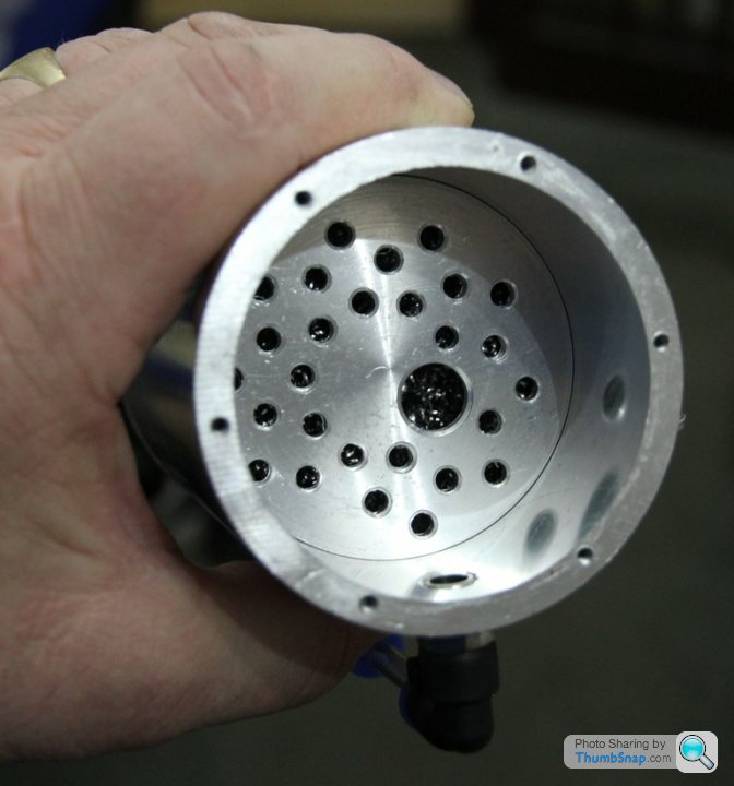
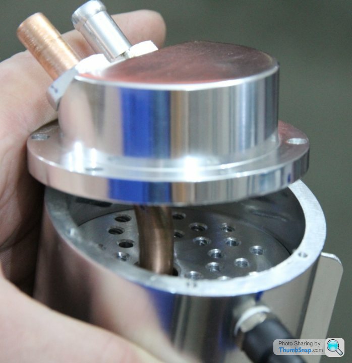
To force the vapour down and through the scourers, I added a drilled baffle to isolate the outlet from the inlet.

With the scourer inserted in the bottom
followed by the baffle
The lid could be installed and sealed.
I replaced the flimsy oil hose in the “V” of the engine between the original separators
with some Aeroquip, high pressure oil cooler hose.

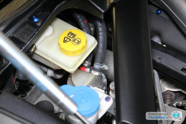
I found a space to install the tank nicely on the rear left of the engine bay, below the brake master cylinder.
and using the original bracket, (seriously over-engineered to hold a thin cable!) to hold the tank in position.

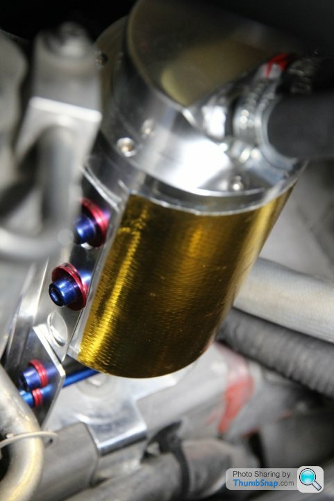
I used some Reflecta-Gold heat shielding I had spare to protect the side of the catch can. It fitted nicely down there.
I then ran one hose from the rear separator into the inlet of my catch can, and the outlet of the can into the “Y” connector at position Y.
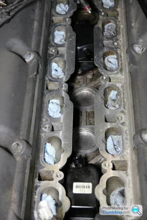
Since making this modification, there has been no recurrance of the pools of oil in the small reservoirs situated just downstream of the throttle bodies, and no more necessity to clean the throttles every service.
I took note that whilst replacing all the hoses and valves concerned with the engine breathers seemed to rectify the fault, this was only a temporary measure, and whilst our cars generally do not do normal mileages, a full rebuild every 30,000 miles or so on the engine breather system indicated an inherant fault in the design.
If the aforementioned parts were an easy and cheap fix, then a more involved modification would be unnecessary, but with the requirement to remove the inlet manifolds to access the parts, and parts and labour going in at over £600.00, I decided to try a more lasting solution.
I firstly needed to understand how it all worked, and why the problem exists in the outset. Using this diagram as a reference, I will try and explain how the system works.
Hoses, part 7, are installed on the throttle bodies, downstream of the throttle plates, so at almost all times, these apply a vacuum to the top of two PCV (Positive Crankcase Ventilation) valves shown at position 2. This applied vacuum on the valves applies a regulated/balanced vacuum to the two oil separators via a “Y” connector and a pipe between positions “X” and “Y” to the rear oil separator, indicated at 11. This is connected directly to the front oil separator (10) by a pipe between them and causes a vacuum condition in the engine assembly.
So that there is not an excessive vacuum held in the crankcase, there are two pipes, “3” and “5” that allow fresh, metered volume of air to flow from the air intake, before the throttle body but after the airflow meters so that there is a constant fresh air flow through the engine case. This explains the name of the system as there is a positive flow of fresh air entering the crankcase, picking up any blowby gasses and oil vapours, and being reburnt through combustion by entering the inlet system.
Where the pipes allow fresh air to enter the engine through the camshaft covers, there is a one-way airflow valve at 4A and 6, known as “duck” valves so that air can enter the camcovers, but not blow out. The duck valves are known to fail, allowing oil vapour to flow back through the air “make-up” pipe and into the intakes, pre throttle.
The “duck” valves are so called because of their resemblance to a ducks bill where air flowing one way pushes the halves of the bill together but air from behind can flow easily.
HOWEVER, this system relies on engine intake vacuum to operate, which is greatest at small throttle openings. At high or full throttle, there is far less vacuum, and under these conditions, the increased blowby gases, build pressure in the crankcase, and this pressure is released through a further duck valve at position 4B where it travels in the opposite direction to the make-up air, and blows into the right hand side intake as well as through the two vacuum pipes.
If everything is working correctly, and the valves and separators are doing their job, there still seems to be an excess of oil vapour escaping into the intakes, usually at large and full throttle when the vacuum is low.
The ONLY place this oil laden vapour can flow is from the two separators into the “Y” connector through the pipe connection at “X-Y”.
I have decided to intercept this vapour at that point and install a proper oil separator/catch can by splicing into that pipe and running the oil laden vapours into an easily cleaned, condensating container, therefore keeping the high acid/fuel laden oil vapour away from the inlets, protecting both the air filters, the throttle plates and engine from ingesting it.
I decided to purchase a cheap oil catch tank to save time but upon opening it up, it was clear to me that it was pretty useless as it was so I went about modifying it as follows.
The empty chamber started out with just two connectors in the lid and a sight glass. There was nothing inside to encourage the oil vapour to condense and separate out and I could see that the vapour would simply go in one pipe and straight out of the other.
Firstly, I added a copper pipe, cross drilled into the inlet pipe aand to filter the air exiting the tank, I installed a small bronze compressor filter to the outlet fitting.
To force the vapours to the middle/lower end of the tank, I then added some stainless steel pan scourers into the bottom of the tank to separate the oil from the vapour.
To force the vapour down and through the scourers, I added a drilled baffle to isolate the outlet from the inlet.
With the scourer inserted in the bottom
followed by the baffle
The lid could be installed and sealed.
I replaced the flimsy oil hose in the “V” of the engine between the original separators
with some Aeroquip, high pressure oil cooler hose.
I found a space to install the tank nicely on the rear left of the engine bay, below the brake master cylinder.
and using the original bracket, (seriously over-engineered to hold a thin cable!) to hold the tank in position.
I used some Reflecta-Gold heat shielding I had spare to protect the side of the catch can. It fitted nicely down there.
I then ran one hose from the rear separator into the inlet of my catch can, and the outlet of the can into the “Y” connector at position Y.
Since making this modification, there has been no recurrance of the pools of oil in the small reservoirs situated just downstream of the throttle bodies, and no more necessity to clean the throttles every service.
No, the inlet manifolds need to be removed to get to the connection between the rearmost block oil serarator and the "Y" piece.
Once fitted however, this is not a problem because the new catch tank is easily accessible and can be removed and drained from the drain plug on the bottom.
Next time it is off though I intend installing a permanent fitting into the wheel arch from the catch tank so that it can be drained very easily without even touching the catch tank itself.
I will be changing my oil and filter this week so will see how the intakes look after a similar trip to Burleigh this last weekend.
Did you see my install on the car? I left the bonnet open for anyone to see.
Gassing Station | Aston Martin | Top of Page | What's New | My Stuff