Different types of throttle pots for RV8?
Discussion


Hi
After using Rover Gauge on my V8S to successfully track down throttle pot error code whilst everything else checks out OK, I've now bought 2 replacements. One was the slotted one from the Range Rover classic which just threw constant error codes once fitted and showed a fixed 11% absolute value on the ECU whether pot is twisted or not. I read somewhere that this means its thrown an out of range error. My existing one shows a 0% position on corrected value and 3-4% on absolute, i.e. self-calibration is working.
Measuring the resistances across the 2 replacement ones they are about 5.7 - 5.9 kOhms across the track.
It is about 200ohms from red to yellow or green depending on which one and position of spindle. This rises to 5.8kOhms as the spindle is rotated and vice versa. I replaced it with another one which is the 2 hole, non-slotted type which was off a Land Rover V8 3.9 and this did the same thing.
The apparent faulty one on my car is 4.8kOhms across the track and rises/falls to same when across red to yellow or green depending on spindle position fully rotated or not.
Can anyone with V8S please measure theirs and let me know their ohm readings before I go out and buy a third one?!
By the way symptoms of running are that of faulty pot / faulty wiring to pot which led me to Rover Gauge and this exercise in the first place.
Any help much appreciated.
Hi
The thing is its doesn't seem to matter what the voltage says measured at the pot/connector as the ECU just reads 11% for any position of the pot. This is what I find so weird. So that's why I was just wondering if anyone else V8S had the same ohms across their pots as these replacements but still had a fully functioning system. Is there any chance with yours you could please just stick a multimeter across the pot track (green + yellow) and then across red + yellow then red + green. No need to twist the pot, just the basic values would be a big help.
cheers
Rob
Hi Rob,
I have the one on the car and a new spare. The spare is in a box marked ETC8495. Both are marked Lucas 84925A. I've checked both, and the resistances are below. for the spare I was measuring at each end of full travel on the pot. For the one on the car I measured with throttle open and closed, but this is presumably not at the extreme ends of the travel on the pot.
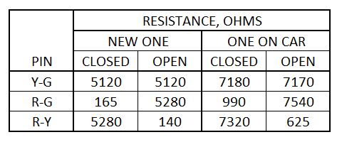
I was rather surprised by the track resistance of the one on the car, but it works fine!
I think your problem lies elsewhere. the next check is to measure the resistance at the pins in the ECU plug, to eliminate (or confirm) faulty wiring. If you suspect the ECU, I have a spare you can borrow for the price of the postage.
Good luck,
Graham
I have the one on the car and a new spare. The spare is in a box marked ETC8495. Both are marked Lucas 84925A. I've checked both, and the resistances are below. for the spare I was measuring at each end of full travel on the pot. For the one on the car I measured with throttle open and closed, but this is presumably not at the extreme ends of the travel on the pot.
I was rather surprised by the track resistance of the one on the car, but it works fine!
I think your problem lies elsewhere. the next check is to measure the resistance at the pins in the ECU plug, to eliminate (or confirm) faulty wiring. If you suspect the ECU, I have a spare you can borrow for the price of the postage.
Good luck,
Graham
Hey graham
Thank you so much for taking the time to come up with this info. But now I'm mystified! Seems there can be a really low tolerance on these things with no apparent problems with function. I will send you an email however to just borrow that spare pot of yours as a final elimination. If this spare works on yours then its all i need to to eliminate the pot.
Thanks again
Rob

The pot connection is open circuit. The ECU goes into limp home mode and uses a default value of 11%. The resistance values of the pot are irrelevant as it is the ratio of the resistances on either side of the pot wiper that are important.
When ECUmate sees an 11% reading it then checks to see if this is a real value or a substituted one and changes the display accordingly. It replaces the bar graph with a text message.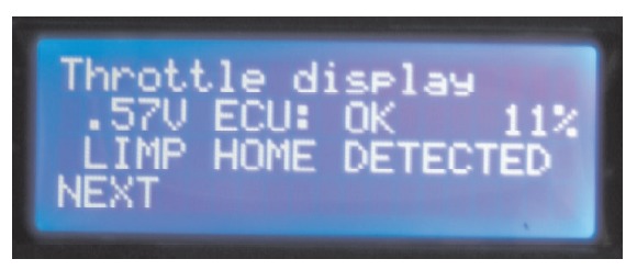
When ECUmate sees an 11% reading it then checks to see if this is a real value or a substituted one and changes the display accordingly. It replaces the bar graph with a text message.
Hmm. Interesting. So 2 new pots are open circuit and the old one isn't. That's really weird too. Unless the connections aren't being made properly at the plug with the 2 new ones. I'll check the voltages at the ECU plug with the 2 new ones as suggested. Thanks for that. At least the ECUmate is showing 11% (limp home) the same as the rover gauge one so I know that at least the info I'm getting is right if very strange.
Cheers
Rob
Cheers
Rob
Hi Rob
I think what Steve is saying is the ECU can't 'see' a valid voltage coming from the throttle pot. I would imagine the resistances are not that relevant as if one end of the throttle pot track is at 5 volts and the other end is at 0 volts then a throttle pot at the midway position would produce a 2.5 volt reading regardless of the track resistance.
Have you managed to try an alternative ecu?
Chris
Steve says the resistance is irrelevant since the TP is simply a voltage divider, which is true for a WORKING TP, but for a damaged one, measuring the resistance can tell you if the track is broken or (less likely) shorting out.
I think your TPs are all okay but your wiring is dodgy, and as a next step I would check the resistance at the ECU plug rather than the TP. Including a waggle test, of course...
Good luck,
Graham
I think your TPs are all okay but your wiring is dodgy, and as a next step I would check the resistance at the ECU plug rather than the TP. Including a waggle test, of course...
Good luck,
Graham
Sounds like a plan.
You will need to measure the voltage with it attached to the ecu - if possible from the pins where they are soldered internally to the pcb.
Not this week but next week I will have some spare time if thats any use.
Examine the solder very closely you can get a very difficult to see hairline crack around pins that can affect connection.
Off Topic-
Very common on old car stereos with seperate speaker connections before they had the current all in one connector arrangement. Speakers would go on and off over bumps.
Just a follow up for future information... It seems the TPS gives a reading of 0 volts between red and green, which appears like open circuit to the ECU even though strictly speaking its not. The reason I had problems with the ECU output showing 11% all the time was that once the ECU read this 0 volts at closed throttle then it would remain a 'fault' all through the motion of the TPS and the fault will just not clear.
Therefore to make it operate correctly at the ECU the TPS needs to be set at say 0.2V and only then is the ECU turned on (re-connect the battery) and then the ECU should read the TPS at say 4-5% absolute and self-calibrate to 0% adjusted. Problem I had was the TPS was at 0 volts when fitted so I had to turn it open to create the 0.2V signal which means its default position was not right, which is also now adjusted.
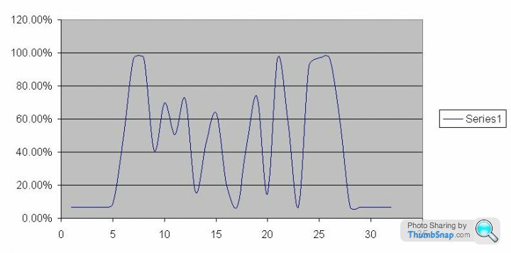
Running issues still exist though! but at least I've eliminated the TPS itself! Here's the logged TPS in action. Nothing weird there I think.
Therefore to make it operate correctly at the ECU the TPS needs to be set at say 0.2V and only then is the ECU turned on (re-connect the battery) and then the ECU should read the TPS at say 4-5% absolute and self-calibrate to 0% adjusted. Problem I had was the TPS was at 0 volts when fitted so I had to turn it open to create the 0.2V signal which means its default position was not right, which is also now adjusted.
Running issues still exist though! but at least I've eliminated the TPS itself! Here's the logged TPS in action. Nothing weird there I think.
Hi Rob,
You need to get Steve's book, or if you've got one, read it! To quote:
"The voltage should change smoothly from 0.26-0.36V to 4.6-5.0V as the throttle is moved from fully closed to fully open".
Now you've got the 'closed' voltage nearly right, how good is the 'open' voltage, and how smooth from one t'other? Which TPS are you using?
How do the other TPSs perform when set correctly?
What are the 'running issues' that led you to suspect the TPS in the first place?
Nice graph, but what are the axes?
It's beginning to sound like you may have a dodgy track in your original TPS if that's the one you've put back, and its giving an error code. Call me.
Graham
hey, yeah knew it should be that voltage range but it just wasn't doing so when new TPS was fitted in place of old one into the screw holes and the ECU error code was throwing me. Anyway, I've got it sorted now anyway.
The graph just shows the TPS position in % terms as the throttle is open and closed against time. It shows the new TPS doing what it should with no apparent drop in signal, although a reading is only taken every 0.5 secs via the logger.
The running issues is something I've been trying to work out for a while. Its v jerky throttle response at low speeds and engine always stutters and tries to stall when trying to drive if started from cold, as if it was flooding the engine. Soon as it hits 50degC the problems recede and it revs smoothly. Had a TVR garage check virtually everything (compression tests, whole ignition system,fuel pressure) and all ok. Their only suggestion left was TPS and/or ECU but I also need to check for air leaks to eliminate that too. Recently there's been periods of flat throttle response too.
To be continued.....
Gassing Station | S Series | Top of Page | What's New | My Stuff