3 pin diagnostics plug wiring?
Discussion


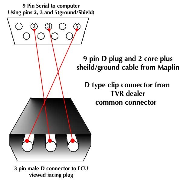
Right i think i have this sussed but i need some help guys. For a 3 pin diagnostic plug, according to a Sagaris diagram the 3 connections are Rx, Tx and Analogue ground, as here:
[URL=http://img199.imageshack.us/i/sagarisworkshopmanualdi.jpg/] [/URL]
If this is correct, then the ecu connections should be 45,46 & 12, according to the MBE website connections for a serial socket:
Comms Pin out for 970/941 ECU
[b]Pin out on 9 Way D Type (Male Connector with Female Receptors) comms lead on Harness
1. Pin 7 ECU =power Ground
2. Pin 46 ECU =Serial Data Transmit (TXD)
3. Pin 45 ECU =Serial Data Receive (RXD)
4. Pin 30 ECU =5V Analogue Output
5. Pin 12 ECU =Analogue Ground
6. Pin 47 ECU = Fuel trim signal Input
7. Pin 10 ECU = Ignition trim Signal input
8. Pin 28 ECU = Boost trim signal input
9. N/C[/b]
Also which is pin 1 & 3? Is it looking at the end of the plug or down the end of it?
[URL=http://img199.imageshack.us/i/sagarisworkshopmanualdi.jpg/]
[/URL]If this is correct, then the ecu connections should be 45,46 & 12, according to the MBE website connections for a serial socket:
Comms Pin out for 970/941 ECU
[b]Pin out on 9 Way D Type (Male Connector with Female Receptors) comms lead on Harness
1. Pin 7 ECU =power Ground
2. Pin 46 ECU =Serial Data Transmit (TXD)
3. Pin 45 ECU =Serial Data Receive (RXD)
4. Pin 30 ECU =5V Analogue Output
5. Pin 12 ECU =Analogue Ground
6. Pin 47 ECU = Fuel trim signal Input
7. Pin 10 ECU = Ignition trim Signal input
8. Pin 28 ECU = Boost trim signal input
9. N/C[/b]
Also which is pin 1 & 3? Is it looking at the end of the plug or down the end of it?

No,I think the problem is that it's a replacement MBE, Non TVR specific, ECU plugged into an early loom, hense there's no internal serial socket and no 3-pin external fly lead, just the 2-pin fault code reader fly lead.
I have diagrams for both the standard 9-pin and 3-pin leads but that's not the problem.
I've checked my 'spare' loom and that's an early one too so it's of no use, what we need is someone with a 'late' ECU that has the 3-pin lead. That person would need to trace back the pins on the fly lead to the corresponding pins on the large ECU connector, they are all numbered.
May have a trawl through the Cerb' wiring diagrams tomorrow and see if I can glean it from there.
Edited to add, I'm not sure I'd be 100% confident that the Sag' wiring is the same as the Cerb' there's 10 years between them!
Tim
Edited by TT Tim on Monday 20th July 22:10
TT Tim said:
No,I think the problem is that it's a replacement MBE, Non TVR specific, ECU plugged into an early loom, hense there's no internal serial socket and no 3-pin external fly lead, just the 2-pin fault code reader fly lead.
I have diagrams for both the standard 9-pin and 3-pin leads but that's not the problem.
I've checked my 'spare' loom and that's an early one too so it's of no use, what we need is someone with a 'late' ECU that has the 3-pin lead. That person would need to trace back the pins on the fly lead to the corresponding pins on the large ECU connector, they are all numbered.
May have a trawl through the Cerb' wiring diagrams tomorrow and see if I can glean it from there.
Edited to add, I'm not sure I'd be 100% confident that the Sag' wiring is the same as the Cerb' there's 10 years between them!
Tim
Thanks for the input Tim. The pin out guide above was taken from the sbd website which covers all the mbe ecus, so regardless of it having an early loom, as long as the pin outs correspond to the relevant ones needed to read the ecu then shouldnt that be correct?I have diagrams for both the standard 9-pin and 3-pin leads but that's not the problem.
I've checked my 'spare' loom and that's an early one too so it's of no use, what we need is someone with a 'late' ECU that has the 3-pin lead. That person would need to trace back the pins on the fly lead to the corresponding pins on the large ECU connector, they are all numbered.
May have a trawl through the Cerb' wiring diagrams tomorrow and see if I can glean it from there.
Edited to add, I'm not sure I'd be 100% confident that the Sag' wiring is the same as the Cerb' there's 10 years between them!
Tim
Edited by TT Tim on Monday 20th July 22:10
Taken from: http://www.sbdev.co.uk/Engine_Management_Systems/E...
941/970 ECU WIRING HARNESS
General 8 Cylinder V8 – Grouped Injection
Issue Date: 04 01 2003
PIN NO. DESIGNATION NOTES
1 NC
2 Barometric Pressure
3 NC 4 Fuel Pressure
5 Air Pump Output
6 Shift Light Output
7 Power Ground
8 Crank Sensor Return
9 Oil Temperature Signal Input
10 Ignition Trim Mapping 07
11 NC
12 Analogue Ground Mapping 05
13 Crank Signal
14 NC
15 Waste gate Valve Drive
16 Spare Digital Input
17 Air Temperature Signal
18 Boost Pressure Signal
19 Ignition Drive
20 Ignition Drive
21 Lambda Signal
22 Gear Position Signal
23 Oil Pressure Signal
24 NC
25 Fuel Pump Relay Drive
26 Power Ground
27 NC
28 Boost Trim Signal Mapping 08
29 NC
30 5V Analogue Mapping 04
31 12V Supply Output
32 NC
33 Tachometer Signal
34 NC
35 TPS Signal
36 Coolant Temperature Signal
37 NC
38 Ignition Drive
39 NC
40 Injector Drive Bank A
41 Radiator Fan Relay Drive
42 Intercooler Spray Drive
43 Spare map able Output
44 Spare map able Output
45 Serial Receive Mapping 03
46 Serial Transmit Mapping 02
47 Fuel Trim Mapping 06
48 5V Analogue TPS, Baro
49 0V Analogue TPS, Baro
Air T, Water T
50 Power Ground
51 Power Ground
52 ECU 12V Supply
53 Injector Drive Bank B
54 NC
55 Ignition Drive
So for correct diagnostics, a Rx,Tx & a analogue ground is needed which on my ecu is pin 45,46 & 12? So all i need to do is tap the 3 pin fly lead into these 3 pins on the ECU?
Edited by sk7ine man on Monday 20th July 22:19
mikesr said:
Your guess at the pins is correct - no change in 10 years 
pin 45 serial receive
pin 46 serial receive
pin 12 ground
pin 45 serial receive
pin 46 serial receive
pin 12 ground
 Great!! i think ive done something right in 31 years of existence!!! Now i cant work out by the diagram above whether pin 3 is on the left looking down the end of the lead or on the right looking "at it"?
If you take the lid off the ECU there are numbers printed on the pcb to identify which pin is which. I think 1 and 46 are numbered, or some such.
The pins in the DB9 connector are numbered. Hope you've got good eyes!
I soldered a cable to the appropriate pins inside the ecu and dangled it out, with a DB9 on the end, so I can connect a longer one when I need to.
A.
The pins in the DB9 connector are numbered. Hope you've got good eyes!
I soldered a cable to the appropriate pins inside the ecu and dangled it out, with a DB9 on the end, so I can connect a longer one when I need to.
A.
Edited by alinton on Monday 20th July 23:23
 that's excellent.
SimonKD said:
SimonKD said:
Hi All
I have the later type ecu layout with the black 3 pin socket dangling out of the ecu. Where can I get the black 3 pin plug to fit this socket?
Regards
Simon
Or does anyone know what this plug/socket is called (RS or Farnell No. etc)?I have the later type ecu layout with the black 3 pin socket dangling out of the ecu. Where can I get the black 3 pin plug to fit this socket?
Regards
Simon
Regards
Simon
This is my ecu below, could i solder a 3-pin / serial connector directly onto the pins within the ecu as below?
[URL=http://img29.imageshack.us/i/21072009910.jpg/] [/URL]
[URL=http://img9.imageshack.us/i/21072009909.jpg/] [/URL]
Also looking at the female end of a serial rs232 plug, i assume the ports go from the top 54321 and on the bottom 9876? just dont want to make a hash of this?!
[URL=http://img29.imageshack.us/i/21072009910.jpg/]
[/URL][URL=http://img9.imageshack.us/i/21072009909.jpg/]
[/URL]Also looking at the female end of a serial rs232 plug, i assume the ports go from the top 54321 and on the bottom 9876? just dont want to make a hash of this?!
Edited by sk7ine man on Tuesday 21st July 22:18
sk7ine man said:
SimonKD said:
SimonKD said:
Hi All
I have the later type ecu layout with the black 3 pin socket dangling out of the ecu. Where can I get the black 3 pin plug to fit this socket?
Regards
Simon
Or does anyone know what this plug/socket is called (RS or Farnell No. etc)?I have the later type ecu layout with the black 3 pin socket dangling out of the ecu. Where can I get the black 3 pin plug to fit this socket?
Regards
Simon
Regards
Simon
Regards
Thomas
billy no brakes said:
I went to maplins and got a USB Serial Converter and it works fine / there is a number on it might be a part number and could be worth checking at Maplins D700319817, Hope that helps
Gary
Thank you, GaryGary
but what i need is the 3-pin plug (female) that is connected to the lead on the driver side.
I will make tha diagnostic cable on my own since it is a simple Rx/Tx serial connection.
Gassing Station | Cerbera | Top of Page | What's New | My Stuff