What is this part, what does it do? I need a new one.
Discussion


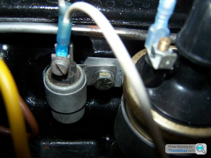
While restoring and rewiring my car I connected the electrics up wrong and suspect I damaged this component and the alternator. Now tach and temp gauge not working. Not sure if the problems are related, would like to get a new part. It is located in front of the coil on a TR6 Engine / TVR 2500 vin # 1878T
Help appreciated and thanks,-Jeff
Help appreciated and thanks,-Jeff

How is it connected up?
Looks like it could be a ballast resistor.
If it is, what it does is ensure that the coil doesn't always get a 12V current. The coil will only receive 12V on starting to aid cold starts and because the start motor takes alot of juice.
If the coil, which is not a 12V coil, is being supplied with a 12V feed constantly it can break, IIRC.
Someone more knowledgable may come along and give you a better explanation and I may be wrong, but from that pic, it looks like a ballast resistor.
No, its a resistor.
It creates a resistance to drop the voltage.
A capacitor stores voltage.
My dad says it might be a suppressor too.
Might be worth taking it off and taking into a local motor factors and see if they can tell you what it is.
Our local one is excellent, gave us all sorts of help with the crossflow.
It creates a resistance to drop the voltage.
A capacitor stores voltage.
My dad says it might be a suppressor too.
Might be worth taking it off and taking into a local motor factors and see if they can tell you what it is.
Our local one is excellent, gave us all sorts of help with the crossflow.
if it is the ballast resistor, it should measure about 1,4 ohms, enough to drop the voltage with 3 volts. does the coil have another lead attached that provides it with 12 v during cranking/starting? it isn't on either of the terminals in the photo.
if it is a suppressor, you won't measure a resistance, unless it is broken.....
the temp gauge should have a feed through a voltage regulator, along with the petrol gauge.
if it is a suppressor, you won't measure a resistance, unless it is broken.....
the temp gauge should have a feed through a voltage regulator, along with the petrol gauge.
Geert- Here is my problem. Not knowing what I was doing when I took the car apart I didn't realize it had a Voltage Regulator (my mistake). The alternator has an internal voltage regulator and the the starter motor has an internal solinoid.
The wiring diagram doesn't show a voltage regulator. What would be the path of electricity on the fuel gauge and the temp gauge?...or How would I correctly connect the voltage regulator to the fuel gauge and the temp gauge.
Another question- The car has two horns. I wired a relay into one horn and now that one works, does each horn need its own relay?
Thanks,-Jeff
the voltage regulator/stabiliser is a small separate metal/tin box, the early ones with a bi-metal, the present ones are electronic. it prevents the instruments needles to flick with drops or increases of voltage due to the switching of components such as indicators, lights, wipers and so on and keeps the feed to the gauges at a steady voltage of around 10 volts. the gauges are earthed through their sensors ( temp- and fuel sender ): the other terminal on the gauge comes from the stabiliser. the stabiliser has a switched feed from the fusebox ( dark green wire ). the wire between the stabiliser and the gauges is/should be darkgreen with a light green tracer. the wire from the temp gauge to the temp sender should be green/blue, from the fuel gauge to the fuelsender green/black. the fuel tank should have a separate earth strap and be sure the fuelsenders base is in good contact with the fuel tank.
it is ok to connect both horns to the relay, providing the relay is 25A or more. depending on where you take the mains to the horns from, make sure to fuse them (separately). also make sure the 2 horns are connected alike to prevent a possible shortcircuit from live + to earth between the two. ( the horns mostly have insulated terminals for + and -, but sometimes the body is - as well with the - terminal fixed to it.
the voltage regulator was/is mounted either behind the instrument panel or underbonnet on the bulkhead/firewall close to the fusebox and/or indicator relay. stabilisers are available from stock.
Edited by geertvanhout on Monday 11th January 23:48
Edited by geertvanhout on Tuesday 12th January 09:31
another thing, forgot to mention yesterday: if the coil is meant to work in conjunction with a ballast resistor, the coils resistance should measure approx 1.8 ohms between the 2 primary terminals ( secundary is high voltage to distributor centre). take all wires off before measuring. in this case you have a 9 volt coil that should work ok together with the ballast resistor. however there should be a ballast bypass wire during cranking/starting providing the 9 volt coil with 12 volt causing a higher secundary voltage, causing a stronger spark that is necessary/convenient when starting up an engine. coils without resistor should measure an internal resistance of around 3,4 ohms. ( again take any wire off to prevent measuring faults).
the bypass wire can be incorporated either in the starter motor solenoid, or as an extra feed from a separate main starting relay, like the ones common to starter motors that donot incorporate a solenoid ( lucas starter solenoid number srb 335 )
this separate solenoid can also be used together with a starter that has a mounted solenoid but no ballast resistor bypass terminal.
Edited by geertvanhout on Tuesday 12th January 20:39
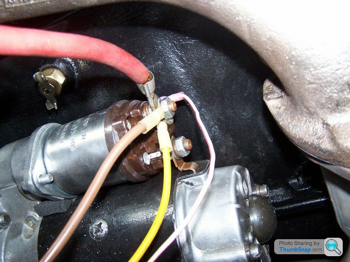
A) Ballast Resistor:
Take a look at this picture of my Starter Solenoid. Check attached image please. I want to make sure I plug the wire leading to the coil in the right position.
I have a question about the flow of electricity: Does the power go directly from the battery through the solenoid and on to the starter motor?
...or does power go from the battery to the starter motor, then from the positive post on the starter, to the solenoid and on to the coil?
There is a spade plug in on the bottom of the starter motor. Is this the plug in for the wire to go out to the solenoid?
Attaching Wires to the Solenoid: Main power bolts onto the stud with the two spade terminal attached. Large spade is power out to amp meter, small spade not needed. Lower small spade goes out to coil.
Is the other bolt for ground? Does the solenoid need to be grounded?
B) Voltage Regulator- I don't have one and can not find out which one to buy for the TVR 2500. Is this a common part I can buy local?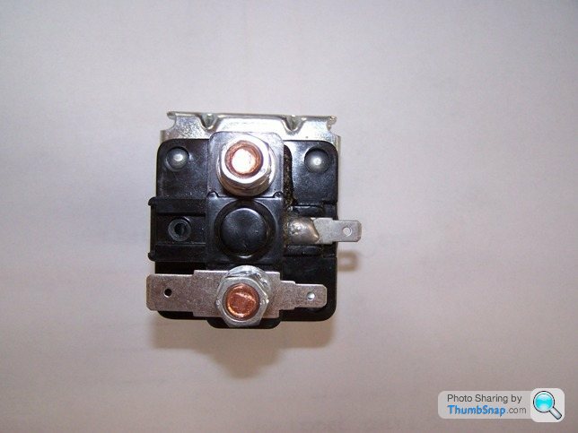

You probably want to look at this....
http://tvr.m-fix.co.uk/Wiring/tvr.m-fix.co.uk%A9m_...
as a good place to start. The starter solenoid is basically a very meaty relay. Big thick wire from battery positive to bolt terminal on solenoid. Big thick wire from other bolt terninal to starter, the starter is earthed (negative) via engine to chassis. When you turn the ignition switch to 'start' the solenoid should be powered (via smaller spade terminals) to engage the starter and, at the same time, the ballast resistor is by-passed to give 12v (nominal) to the coil. Once the ignition is released (to 'on') ignition feed to the coil is through the ballast resistor to give the reduced voltage required.
If you wire up the solenoid but leave the starter disconnected you should hear a "click" as you turn the ignition to 'start' - that's the solenoid engaging to deliver power to the starter motor.
At least, that's how I think it's supposed to work!
No doubt someone will be along in a minute to correct me!
Good luck,
Phil
Edited by ATE399J on Friday 15th January 09:25
BUT, that looks like the wrong starter solenoid for a ballasted system ...(I might be wrong from the image) but on the opposite side to the minor connection should be the output to the cold start 12v supply.
Adrian@
It is use-able as it is but you might have a minor yellow and brown wire hanging about that area with the need or want to plug it into something.
Adrian@
It is use-able as it is but you might have a minor yellow and brown wire hanging about that area with the need or want to plug it into something.
Edited by Adrian@ on Friday 15th January 10:03
Adrian- I am convinced that my starter motor has a solinoid attached to it and I don't need an independant starter sonenoid. But I want to confirm where I attach the wire running from the starter solenoid to the coil. Right beside the white/red wire running to the ignition there is an open spade (you can't see it in the picture). Would this be the plug in for the coil wire?

Hi Jeff,
There is not a ignition live feed from the starter...BUT Yes, you have a solenoid on the starter...you need an ignition key cranking live to the Lucar connector IN (this cranks the engine) and the bullet goes (OUT) to the coil + side of the ballast resistor and then a link to the + of the coil (so that when the engine is cranking you get 12V to the coil and when not cranking you get 0V...whilst you then have a ignition switched 12v to the other end of the ballest (whilst running the coil then get the ballasted 9V).
Adrian@
IF you do not have the ballast then it is 12V lucar ---cranking and ignition switched 12V to the coil.
Edited to say that without looking I cannot remember the 12 volt lucar/bullet way around AND the starter that I had on the shelf here has TWO Lucar connections (I went out to check which way it was around ...which is a first for ME) I am not going search any more cars as it is raining cats and dogs here getting rid of the snow!!!
OK back to the plot..the terminal that is 90 degrees to the two main posts on the starter solenoid is the OUT switched by the starter supply (so this supplies the 12v hot start out to the coil + side of the ballast resistor)
Edited by Adrian@ on Monday 18th January 21:40
Gassing Station | TVR Classics | Top of Page | What's New | My Stuff