Discussion


Norman don't die of shock, I have finally got round to looking at it!
Here's the test setup
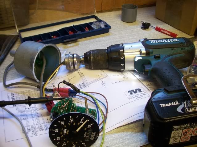
Yes Norman that is the same sender you sent me covered in sh!t!
I gave it a bit of a clean.
Don't panic the cog comes off the end by removing a circlip.
The output from the sender is a nice crisp 12v square wave that varies in frequency accoring to the speed (as you'd expect).
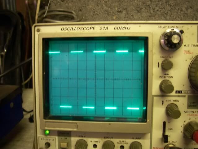
Each cm vertically represents 2 volts, so 6 squares = 12 volts.
You can see the volts/div control to the botton right of the pic if you're interested.
Anyway I have spent a lot of time trying to work out the speedo problem to the point that I have just ordered some electronic components, I hope thats OK Norman.
If I'm right then I'll return a fully working speedo to you free of charge.
I have so far identified one problem with the speedo - there may of course be a second fault once that is resolved.
Watch this space!
Here's the test setup
Yes Norman that is the same sender you sent me covered in sh!t!
I gave it a bit of a clean.
Don't panic the cog comes off the end by removing a circlip.
The output from the sender is a nice crisp 12v square wave that varies in frequency accoring to the speed (as you'd expect).
Each cm vertically represents 2 volts, so 6 squares = 12 volts.
You can see the volts/div control to the botton right of the pic if you're interested.
Anyway I have spent a lot of time trying to work out the speedo problem to the point that I have just ordered some electronic components, I hope thats OK Norman.
If I'm right then I'll return a fully working speedo to you free of charge.
I have so far identified one problem with the speedo - there may of course be a second fault once that is resolved.
Watch this space!

Well chaps I have to say this was a great help. You may have been aware of a long running issue that I'd been writing up on the TVRCC web site - http://www.tvr-car-club.co.uk/forum/forum_posts.as... -
The over-revving when drawing to a halt took an interesting turn when I noticed that if I'd stopped on a hill the engine revs died down as normal but in neutral, clutch out, if I rolled forward the engine revs picked up to 2000. The focus now was very firmly on the speed sensor so I took the plunge and pulled it out of the car (bit fiddly!) and set up the test rigs as per above.
This is what we got.....
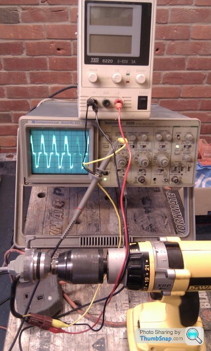
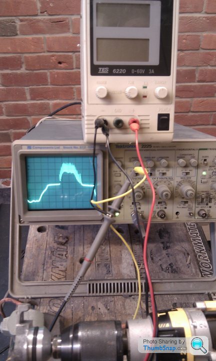
This is a shot of a single waveform through one cycle, not exactly a crisp squarewave. Turning the sensor sent the whole output into paroxisms. The noise on the positive half cycle is very strange.
Took the car out without the sensor and no problems. Hussar!!
The over-revving when drawing to a halt took an interesting turn when I noticed that if I'd stopped on a hill the engine revs died down as normal but in neutral, clutch out, if I rolled forward the engine revs picked up to 2000. The focus now was very firmly on the speed sensor so I took the plunge and pulled it out of the car (bit fiddly!) and set up the test rigs as per above.
This is what we got.....
This is a shot of a single waveform through one cycle, not exactly a crisp squarewave. Turning the sensor sent the whole output into paroxisms. The noise on the positive half cycle is very strange.
Took the car out without the sensor and no problems. Hussar!!
Barkychoc said:
Norman don't die of shock, I have finally got round to looking at it!
Here's the test setup
Yes Norman that is the same sender you sent me covered in sh!t!
I gave it a bit of a clean.
Don't panic the cog comes off the end by removing a circlip.
The output from the sender is a nice crisp 12v square wave that varies in frequency accoring to the speed (as you'd expect).
Each cm vertically represents 2 volts, so 6 squares = 12 volts.
You can see the volts/div control to the botton right of the pic if you're interested.
Anyway I have spent a lot of time trying to work out the speedo problem to the point that I have just ordered some electronic components, I hope thats OK Norman.
If I'm right then I'll return a fully working speedo to you free of charge.
I have so far identified one problem with the speedo - there may of course be a second fault once that is resolved.
Watch this space!
Thats a fast bench you have there, it looks like it's doing about 143mph Here's the test setup
Yes Norman that is the same sender you sent me covered in sh!t!
I gave it a bit of a clean.
Don't panic the cog comes off the end by removing a circlip.
The output from the sender is a nice crisp 12v square wave that varies in frequency accoring to the speed (as you'd expect).
Each cm vertically represents 2 volts, so 6 squares = 12 volts.
You can see the volts/div control to the botton right of the pic if you're interested.
Anyway I have spent a lot of time trying to work out the speedo problem to the point that I have just ordered some electronic components, I hope thats OK Norman.
If I'm right then I'll return a fully working speedo to you free of charge.
I have so far identified one problem with the speedo - there may of course be a second fault once that is resolved.
Watch this space!

Mark
Barkychoc said:
If that sensor is your problem it might be worth trying to open it up - the one I have looked at looks like it is all metal but on closer inspection it looks like 2 seperate parts glued together - there is a glue line if you look carefully.
The glue is immovable. Also the whole inside of the unit looks 'potted', as in filled with a sealant.
Quite right. Got the new replacement yesterday. Turns nice and smooth. Just got to sort out the plug as the old one has to go back on.
The original has Brown, Yellow, Black and the new has Brown, Black/Brown and Yellow/Brown.
Any idea what goes to which?
I think the circuit diagram for the original has :-
Brown - +12v
Black - Earth
Yellow - Signal
The original has Brown, Yellow, Black and the new has Brown, Black/Brown and Yellow/Brown.
Any idea what goes to which?
I think the circuit diagram for the original has :-
Brown - +12v
Black - Earth
Yellow - Signal
Gassing Station | S Series | Top of Page | What's New | My Stuff