Chris' Mazda 323F V6
Discussion


I've been planning an engine bay refresh for a little while. If the bodywork was sub-par then I could at least make the most interesting part of the car look better IMO.

I started to hoard parts including service items
Magnatec 5W40 (oil viscosity has always been a topic of discussion amongst owners. Some say 5W30, some say 10W40 so I went with inbetween)
Oil filter
Magnetic sump plug
Engine flush
Spark Plugs (NGK BKR6E-11)
K&N Panel Filter (found this one new old stock)
K&N Recharge kit
8mm Ignition Leads from (https://www.ebay.co.uk/sch/i.html?_ssn=mrretroleadsltd&store_name=mrretroleadsplugs&_oac=1&_trksid=p4429486.m3561.l161211)
Inlet Manifold Gasket x2 (BGA MG6500)
Rocker Cover Gaskets (Elring 658.220 & 658.980)
OEM PCV Grommet (E30113338A same as a MX5 NA/NB)
OEM Oil Cap (045310250A same as a MX5 NA/NB)
OEM Inlet Manifold O Ring x2 (K80113163B)
OEM Throttle Body Gasket (KL4713655}
OEM Idle Control Valve Gasket (K80113W89)
I also stocked up on various stainless hardware (obviously measuring the ones I need)
Stripping it down 'should' be quite easy. Having only removed the airbox prior I was keen to learn more about this particular engine.

I started off with removing the airbox,intake hose and disconnecting the solenoid plugs and hoses on the side of the airbox. The inlet manifold has x8 8mm (13mm head) bolts and x4 8mm nuts either end of the flange.
Followed by the ignition leads, PCV breathers, fuel rail hoses and plug, brake servo hose, idle control valve and the associated solenoid plugs around the back of the throttle body.
There's a Y joiner to the left side of the inlet manifold, these vacuum lines goto each VRIS actuator and solenoid. While disconnecting this I ended up breaking the one way valve. I cover more of this in the Youtube video.
There's a bracket brace at the back of the inlet manifold, which was the last thing to remove.

Youtube video can be seen here
https://www.youtube.com/watch?v=emkthVWC_6w
I started to hoard parts including service items
Magnatec 5W40 (oil viscosity has always been a topic of discussion amongst owners. Some say 5W30, some say 10W40 so I went with inbetween)
Oil filter
Magnetic sump plug
Engine flush
Spark Plugs (NGK BKR6E-11)
K&N Panel Filter (found this one new old stock)
K&N Recharge kit
8mm Ignition Leads from (https://www.ebay.co.uk/sch/i.html?_ssn=mrretroleadsltd&store_name=mrretroleadsplugs&_oac=1&_trksid=p4429486.m3561.l161211)
Inlet Manifold Gasket x2 (BGA MG6500)
Rocker Cover Gaskets (Elring 658.220 & 658.980)
OEM PCV Grommet (E30113338A same as a MX5 NA/NB)
OEM Oil Cap (045310250A same as a MX5 NA/NB)
OEM Inlet Manifold O Ring x2 (K80113163B)
OEM Throttle Body Gasket (KL4713655}
OEM Idle Control Valve Gasket (K80113W89)
I also stocked up on various stainless hardware (obviously measuring the ones I need)
Stripping it down 'should' be quite easy. Having only removed the airbox prior I was keen to learn more about this particular engine.
I started off with removing the airbox,intake hose and disconnecting the solenoid plugs and hoses on the side of the airbox. The inlet manifold has x8 8mm (13mm head) bolts and x4 8mm nuts either end of the flange.
Followed by the ignition leads, PCV breathers, fuel rail hoses and plug, brake servo hose, idle control valve and the associated solenoid plugs around the back of the throttle body.
There's a Y joiner to the left side of the inlet manifold, these vacuum lines goto each VRIS actuator and solenoid. While disconnecting this I ended up breaking the one way valve. I cover more of this in the Youtube video.
There's a bracket brace at the back of the inlet manifold, which was the last thing to remove.
Youtube video can be seen here
https://www.youtube.com/watch?v=emkthVWC_6w
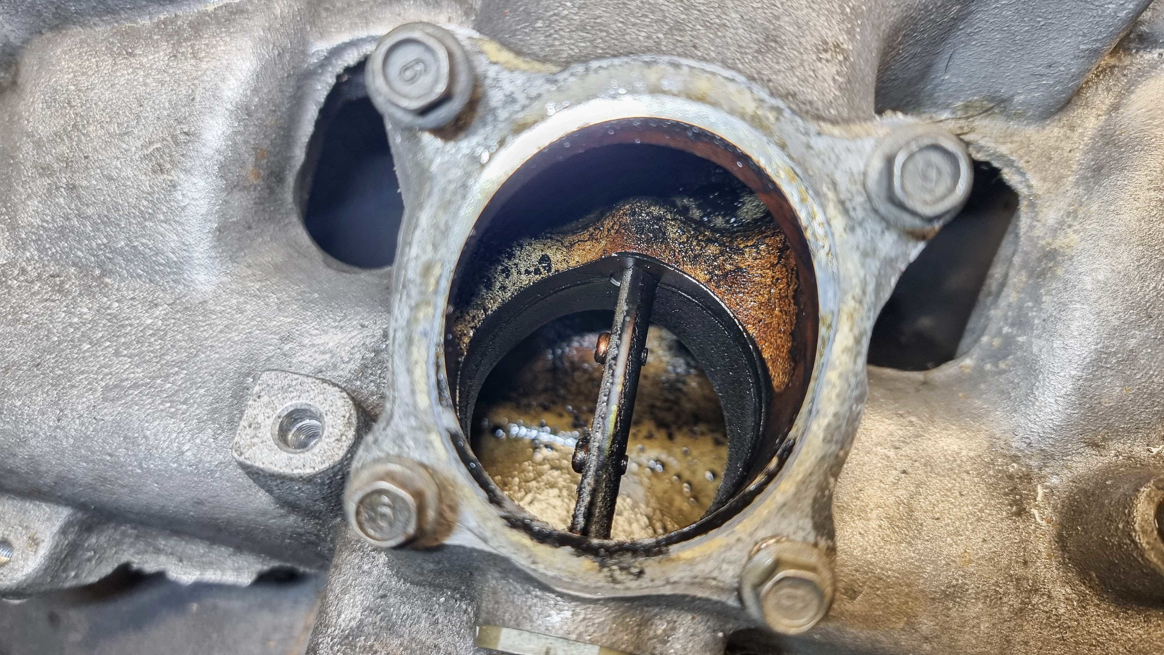
With it finally on the work bench I could begin cleaning it inside and out. I didn't realise how bad it was inside, nothing some aerosol brake and clutch cleaner couldn't sort.
With the top cover removed, it revealed one of the VRIS butterflys
And here's the other butterfly on the end, which has the link pipe connected to it.

Other side of the link pipe


Inlet side behind the throttle body

Throttle Body

Eeeek!

The previous owner had painted the rocker covers last year in what looks to be a wrinkle black finish. It was ok, but I felt the engine bay needed some colour

I used some Motip Paint Remover to strip the paint from the covers. The first one took a little longer because I was too impatient in the video and started to scrape it too soon. It's best to leave it for 5mins+ and let the paint really bubble up.


With the various componants now prepped and masked up it was ready for paint. Etch primer followed by Simoniz Wheel Steel and then their Clear Lacquer


With both rocker covers now back to bare metal, they were degreased and had the baffle plates removed ready for etch primer and then white primer.

Next up was the top coat, I went with Honda Indy Yellow Pearl

It's hard to see the flake because it's so fine but it does pop nicely under direct light

With the lacquer left to dry over night, the next day it was finally time to reassemble. Starting with the baffle plates, I used some RTV sealant around the plates along with some threadlock on the screws.


Going back to the broken one way valve under the inlet manifold. I got a universal valve from work but made the hose coming off the vacuum chamber longer, making the valve more accessible. While I was trimming down the hose to make it fit better, instead of pulling the valve off, I ended up pulling off the barb I had previously glued on.
Annoyingly this was the LAST thing to do. I retraced my steps and removed the inlet manifold (again) to gain access to the broken barb.

I should have done this on the work bench, but you live and learn The barb pushes in but without doing a smoke leak test I'm unsure how well sealed it is.
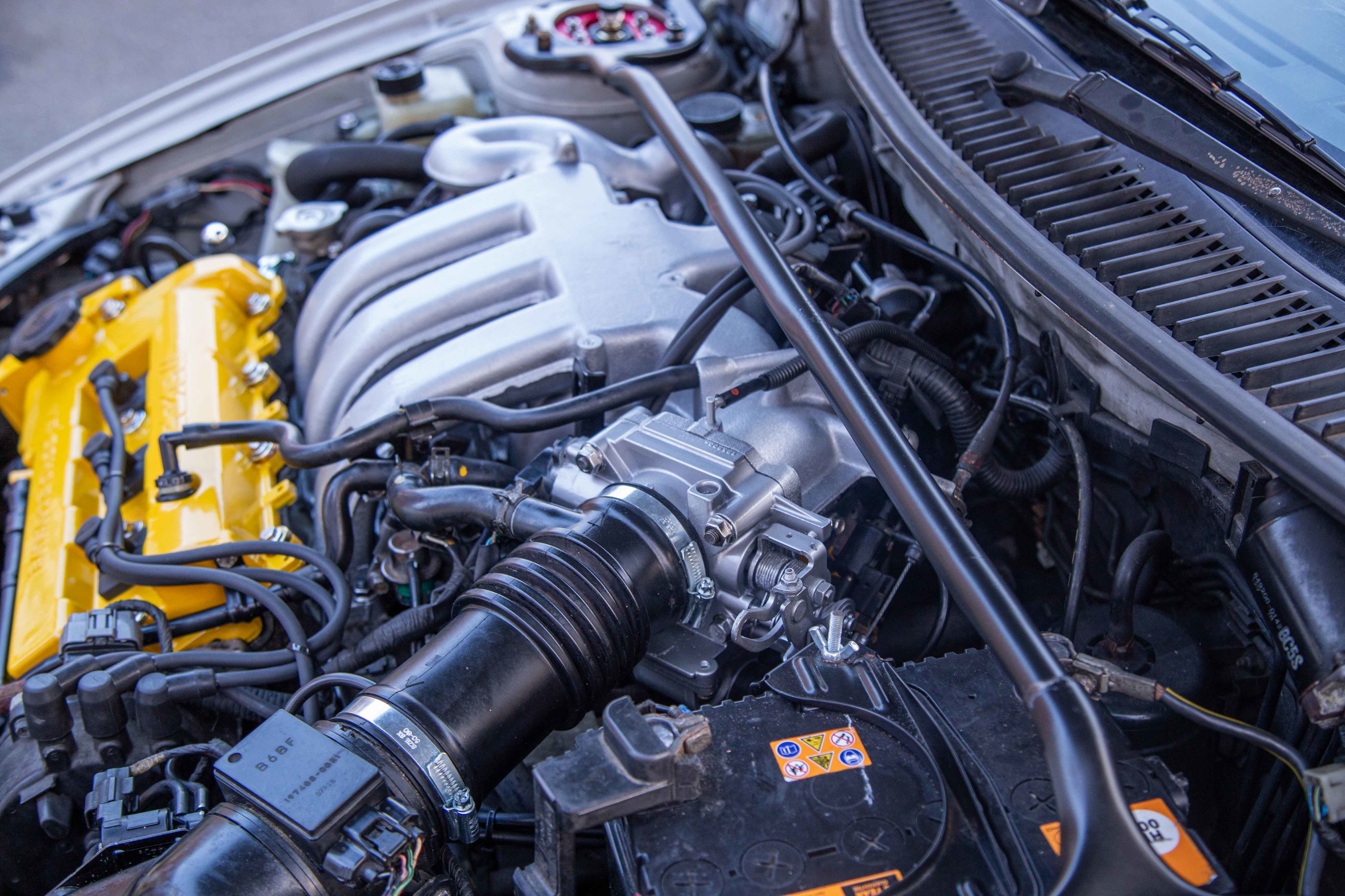
So to conclude this update, here's a before photo

After


I painted various brackets and pipes in Simoniz Tough Satin Black, it's one of my favourite paints to use

It turns out the dipstick handle isn't designed to be leant on, ooops! Luckily I had a solution stashed away which I knew would come in handy at some point.
Jass Performance make a handle specifically for broken MX5 dipsticks and luckily it fits the 323F too

Strut Brace nuts still need replacing after I found out they're M10 x 1.25

Stainless hardware makes all the difference (don't worry, I used threadlock on every single one). Zinc was an option, but I didn't know if it would be too much yellow


My Part 2 video on Youtube can be viewed here
https://www.youtube.com/watch?v=XpzIe_HieNU&t=...
With the top cover removed, it revealed one of the VRIS butterflys
And here's the other butterfly on the end, which has the link pipe connected to it.
Other side of the link pipe
Inlet side behind the throttle body
Throttle Body
Eeeek!
The previous owner had painted the rocker covers last year in what looks to be a wrinkle black finish. It was ok, but I felt the engine bay needed some colour
I used some Motip Paint Remover to strip the paint from the covers. The first one took a little longer because I was too impatient in the video and started to scrape it too soon. It's best to leave it for 5mins+ and let the paint really bubble up.
With the various componants now prepped and masked up it was ready for paint. Etch primer followed by Simoniz Wheel Steel and then their Clear Lacquer
With both rocker covers now back to bare metal, they were degreased and had the baffle plates removed ready for etch primer and then white primer.
Next up was the top coat, I went with Honda Indy Yellow Pearl
It's hard to see the flake because it's so fine but it does pop nicely under direct light
With the lacquer left to dry over night, the next day it was finally time to reassemble. Starting with the baffle plates, I used some RTV sealant around the plates along with some threadlock on the screws.
Going back to the broken one way valve under the inlet manifold. I got a universal valve from work but made the hose coming off the vacuum chamber longer, making the valve more accessible. While I was trimming down the hose to make it fit better, instead of pulling the valve off, I ended up pulling off the barb I had previously glued on.
Annoyingly this was the LAST thing to do. I retraced my steps and removed the inlet manifold (again) to gain access to the broken barb.
I should have done this on the work bench, but you live and learn
The barb pushes in but without doing a smoke leak test I'm unsure how well sealed it is.So to conclude this update, here's a before photo
After
I painted various brackets and pipes in Simoniz Tough Satin Black, it's one of my favourite paints to use
It turns out the dipstick handle isn't designed to be leant on, ooops! Luckily I had a solution stashed away which I knew would come in handy at some point.
Jass Performance make a handle specifically for broken MX5 dipsticks and luckily it fits the 323F too
Strut Brace nuts still need replacing after I found out they're M10 x 1.25
Stainless hardware makes all the difference (don't worry, I used threadlock on every single one). Zinc was an option, but I didn't know if it would be too much yellow
My Part 2 video on Youtube can be viewed here
https://www.youtube.com/watch?v=XpzIe_HieNU&t=...

hoodedreeper said:
Import number plates and yellow fog tint is usually my 2 go-to changes when I get a new car. The next time the bumper is off I may give it a try and see how it looks
Love a yellow fog lamp; I put a pair of yellow Cibie foglamps on my first car, a mkI XR2 back in 1990 
roadie said:
That looks mega, great work! Have you noticed any difference in performance or economy since cleaning the intake parts?
The revs do seem to pick up better. The VRIS isn't working due to the broken barb on the vacuum chamber. I also found out the one way check valve I broke is also for the VRIS.I've got replacement parts on their way from Japan, will be a few weeks until they land at the doorstep so it'll be sluggish for the time being.
trails said:
hoodedreeper said:
Import number plates and yellow fog tint is usually my 2 go-to changes when I get a new car. The next time the bumper is off I may give it a try and see how it looks
Love a yellow fog lamp; I put a pair of yellow Cibie foglamps on my first car, a mkI XR2 back in 1990 The only thing you can see is the glass lens itself, you can't get behind it without removing the bumper
hoodedreeper said:
The real reason why I haven't tinted them is because I was going to eventually attempt to make my own fibreglass covers. But I'm struggling to find a way to secure them.
The only thing you can see is the glass lens itself, you can't get behind it without removing the bumper
Covers would look very JDM. A challenging project to get them to look right, good luck The only thing you can see is the glass lens itself, you can't get behind it without removing the bumper
Since the day I went to view and test drive the car, the clutch biting point was very high. To the point where my foot would only rise half an inch after the bite to the end of the pedal travel. Knowing this I've been driving with care to prolong the life before I could get it changed. It hadn't slipped at all up until 10 or so days ago.
My friend Danny came to the rescue and offered to help guide me through the job. I've only changed one clutch and that was on my Colt CZT with the help of another friend.
I apologise for the lack of photos, I did make a short video for Youtube but was unable to do a full on one due to copyright music in the background.
First start off by disconnecting the battery and remove the battery clamp, battery and battery tray. Next up is the intake hose and airbox, make sure you mark the vacuum hoses and put them back on the correct way.
Locate the starter motor on top left side of the gearbox underneath the distributor. Disconnect the two 12mm nuts and unplug the space connector on top. The starter motor has 3 bolts fixing it to the gearbox.
We decided to keep the slave cylinder connected and removed the 2 bolts that holds it to the side of the gearbox. Follow the clutch line along and it'll join to a short flexible hose which is attached to an L shaped bracket, this needs to be unbolted from the top of the gearbox.
Behind this towards the engine block is a large bracket that secures part of a electrical loom, this also needs unbolting.
Further to the right towards the rear of the engine block is the fuel filter in a cage bracket. I removed the long 10mm bolt on the cage bracket and pulled the filter out. There's two trim clips holding the electrical loom to the same bracket. Follow the bracket along the back of the engine and there's a bolt and captive nut, we slackened this to allow the bracket to move more freely.
In this area there's two plugs, one is the speedo drive and the other is the reverse light switch.
The last thing to do (from memory) at the top of the gearbox is to crack off the bell housing bolts. At the top centre there are two and one more to the right. On the left hand side of the gearbox, there's two more bolts and a third the opposite side (exhaust downpipe) which we originally missed.
Time to raise the ramp and start the removal underneath.
There's a horizontal curved brace with 2 bolts either side, this needs removing. Next was the long brace that goes from the cross member to subframe. The front has 2 bolts and the rear has 2 nuts. Towards the front of the brace is the front gearbox mount, there's two nuts here. With all of those removed the brace can be lifted away. The front gearbox mount has a single bolt that passes through, the round mount will then pull out. Make sure you don't loose the large washers and rubber bushes for the long brace.
You'll see two rods coming from the bottom of the gear stick,one is longer than the other. The short one is the gear selector and has a single bolt. The other goes to the gearbox and has a stud, the nut on mine stopped turning so it ended up removing the stud too.
We'll come back to the rear engine mount in a moment.
Drain the gearbox fluid. The drain plug is on the bottom of the gearbox, its a large bolt 22mm or 23mm (I can't remember sorry)
It's time to remove the wheels. The driveshaft hub nut is 32mm. Unbolting the lower ball joint will help swing the hub up to the side, giving you more access to the driveshaft once its been released from the hub. There's two options to remove the ball joint.
Option 1: Remove the pinch bolt leaving the ball joint on the suspension arm. This carries a risk of splitting the protective boot.
Option 2: Remove the ball joint from the suspension arm. There's a nut and bolt nearest the front and a single nut on top.
We went with option 2
The driver side driveshaft has a centre support bracket/bearing. There's two bolts attaching it to the engine block. With those removed, use a pry bar to help lever the driveshaft out from the gearbox. You may need to wiggle the inner joint while doing this to help.
The passenger side drivehaft is shorter so no need to remove any additional brackets. Removal from the gearbox is the same.
Lets re-look at the rear mount, this had 3 bolts. Two are above the passenger drive shaft and the other is slightly lower down next to the longer gear selector rod that you removed (the one with the stud)
With a transmission jack we took the weight of the gearbox and removed the bell housing bolts. Making sure nothing was getting caught on and around as we slowly lowered it down. Luckily it didn't need lifting/tilting, it came straight down.


We gave the gearbox a thorough clean inside and the areas which were damp on the outside. I checked the clutch plate went on the input shaft spline to check fitment and it was all ok. Using an alignment took, we could make sure the plate was central on the clutch cover before we bolted it to the flywheel.
The release bearing supplied was wrong. Left is the original and the right is the one supplied

Although it slid over the selector fork fine, the top part of the release bearing where the cover/cage crimps to itself that was fouling the inside of the gearbox. It's the part at 12 o'clock, on the right side item. We had no option but to re-use the old one.
The old (ADL Blueprint) correct release bearing FCR54-58

The new replacement (ADL Blueprint) and incorrect release bearing TKS54-33K

A photo of the old release bearing installed. You can see the clearance at the top near the casing

While I was making sure the clutch plate and cover was aligned, Danny gave the face of the flywheel a clean with some brake cleaner and sandpaper.

Clutch installed and torqued to spec

Refitting was the reversal. Make sure you refill the gearbox with 75W90, capacity is 2.7L.

Some Torque Setting
Front Hub Nut - 236>319 Nm
Clutch Cover - 17-23 Nm
My Youtube video can be seen here:
https://www.youtube.com/watch?v=DBK5y1KLZh4&t=...
My friend Danny came to the rescue and offered to help guide me through the job. I've only changed one clutch and that was on my Colt CZT with the help of another friend.
I apologise for the lack of photos, I did make a short video for Youtube but was unable to do a full on one due to copyright music in the background.
First start off by disconnecting the battery and remove the battery clamp, battery and battery tray. Next up is the intake hose and airbox, make sure you mark the vacuum hoses and put them back on the correct way.
Locate the starter motor on top left side of the gearbox underneath the distributor. Disconnect the two 12mm nuts and unplug the space connector on top. The starter motor has 3 bolts fixing it to the gearbox.
We decided to keep the slave cylinder connected and removed the 2 bolts that holds it to the side of the gearbox. Follow the clutch line along and it'll join to a short flexible hose which is attached to an L shaped bracket, this needs to be unbolted from the top of the gearbox.
Behind this towards the engine block is a large bracket that secures part of a electrical loom, this also needs unbolting.
Further to the right towards the rear of the engine block is the fuel filter in a cage bracket. I removed the long 10mm bolt on the cage bracket and pulled the filter out. There's two trim clips holding the electrical loom to the same bracket. Follow the bracket along the back of the engine and there's a bolt and captive nut, we slackened this to allow the bracket to move more freely.
In this area there's two plugs, one is the speedo drive and the other is the reverse light switch.
The last thing to do (from memory) at the top of the gearbox is to crack off the bell housing bolts. At the top centre there are two and one more to the right. On the left hand side of the gearbox, there's two more bolts and a third the opposite side (exhaust downpipe) which we originally missed.
Time to raise the ramp and start the removal underneath.
There's a horizontal curved brace with 2 bolts either side, this needs removing. Next was the long brace that goes from the cross member to subframe. The front has 2 bolts and the rear has 2 nuts. Towards the front of the brace is the front gearbox mount, there's two nuts here. With all of those removed the brace can be lifted away. The front gearbox mount has a single bolt that passes through, the round mount will then pull out. Make sure you don't loose the large washers and rubber bushes for the long brace.
You'll see two rods coming from the bottom of the gear stick,one is longer than the other. The short one is the gear selector and has a single bolt. The other goes to the gearbox and has a stud, the nut on mine stopped turning so it ended up removing the stud too.
We'll come back to the rear engine mount in a moment.
Drain the gearbox fluid. The drain plug is on the bottom of the gearbox, its a large bolt 22mm or 23mm (I can't remember sorry)
It's time to remove the wheels. The driveshaft hub nut is 32mm. Unbolting the lower ball joint will help swing the hub up to the side, giving you more access to the driveshaft once its been released from the hub. There's two options to remove the ball joint.
Option 1: Remove the pinch bolt leaving the ball joint on the suspension arm. This carries a risk of splitting the protective boot.
Option 2: Remove the ball joint from the suspension arm. There's a nut and bolt nearest the front and a single nut on top.
We went with option 2
The driver side driveshaft has a centre support bracket/bearing. There's two bolts attaching it to the engine block. With those removed, use a pry bar to help lever the driveshaft out from the gearbox. You may need to wiggle the inner joint while doing this to help.
The passenger side drivehaft is shorter so no need to remove any additional brackets. Removal from the gearbox is the same.
Lets re-look at the rear mount, this had 3 bolts. Two are above the passenger drive shaft and the other is slightly lower down next to the longer gear selector rod that you removed (the one with the stud)
With a transmission jack we took the weight of the gearbox and removed the bell housing bolts. Making sure nothing was getting caught on and around as we slowly lowered it down. Luckily it didn't need lifting/tilting, it came straight down.
We gave the gearbox a thorough clean inside and the areas which were damp on the outside. I checked the clutch plate went on the input shaft spline to check fitment and it was all ok. Using an alignment took, we could make sure the plate was central on the clutch cover before we bolted it to the flywheel.
The release bearing supplied was wrong. Left is the original and the right is the one supplied
Although it slid over the selector fork fine, the top part of the release bearing where the cover/cage crimps to itself that was fouling the inside of the gearbox. It's the part at 12 o'clock, on the right side item. We had no option but to re-use the old one.
The old (ADL Blueprint) correct release bearing FCR54-58
The new replacement (ADL Blueprint) and incorrect release bearing TKS54-33K
A photo of the old release bearing installed. You can see the clearance at the top near the casing
While I was making sure the clutch plate and cover was aligned, Danny gave the face of the flywheel a clean with some brake cleaner and sandpaper.
Clutch installed and torqued to spec
Refitting was the reversal. Make sure you refill the gearbox with 75W90, capacity is 2.7L.
Some Torque Setting
Front Hub Nut - 236>319 Nm
Clutch Cover - 17-23 Nm
My Youtube video can be seen here:
https://www.youtube.com/watch?v=DBK5y1KLZh4&t=...
Nearly bought a very clean 1.5 petrol one of these before I mistakenly purchased the worst car I've ever had (2006 Beetle) last year. Really wish I'd have gone for it now as I love how they look.
Made it worse as I saw the car drive past me the other day and it looked very nice! I think I'd have made an extra effort if it had a V6 though
Made it worse as I saw the car drive past me the other day and it looked very nice! I think I'd have made an extra effort if it had a V6 though
I'm doing some catch up with the build thread. There's been lots of little jobs but nothing really worthy of its own update.
While doing the clutch change we swapped over the passenger side gearbox mount. The bracket that bolts to the gearbox is different on the V6 and I so happened to have ordered a 1.5/1.8 mount *eye roll*
Luckily that bracket is on a spindle that passes through the bush mount and is held on by a large nut. The bush itself looked the same so we swapped the bracket over and it all bolted into place.
The reason for the change was because I get a knock when changing gears and sometimes under harsh acceleration. I had purchased all 4 mounts but we only had time to do the one (which made sense because of the clutch change).
Although we did look at the front mount, but the one supplied was incrorrect. Turns out the studs are wider on the V6 model.
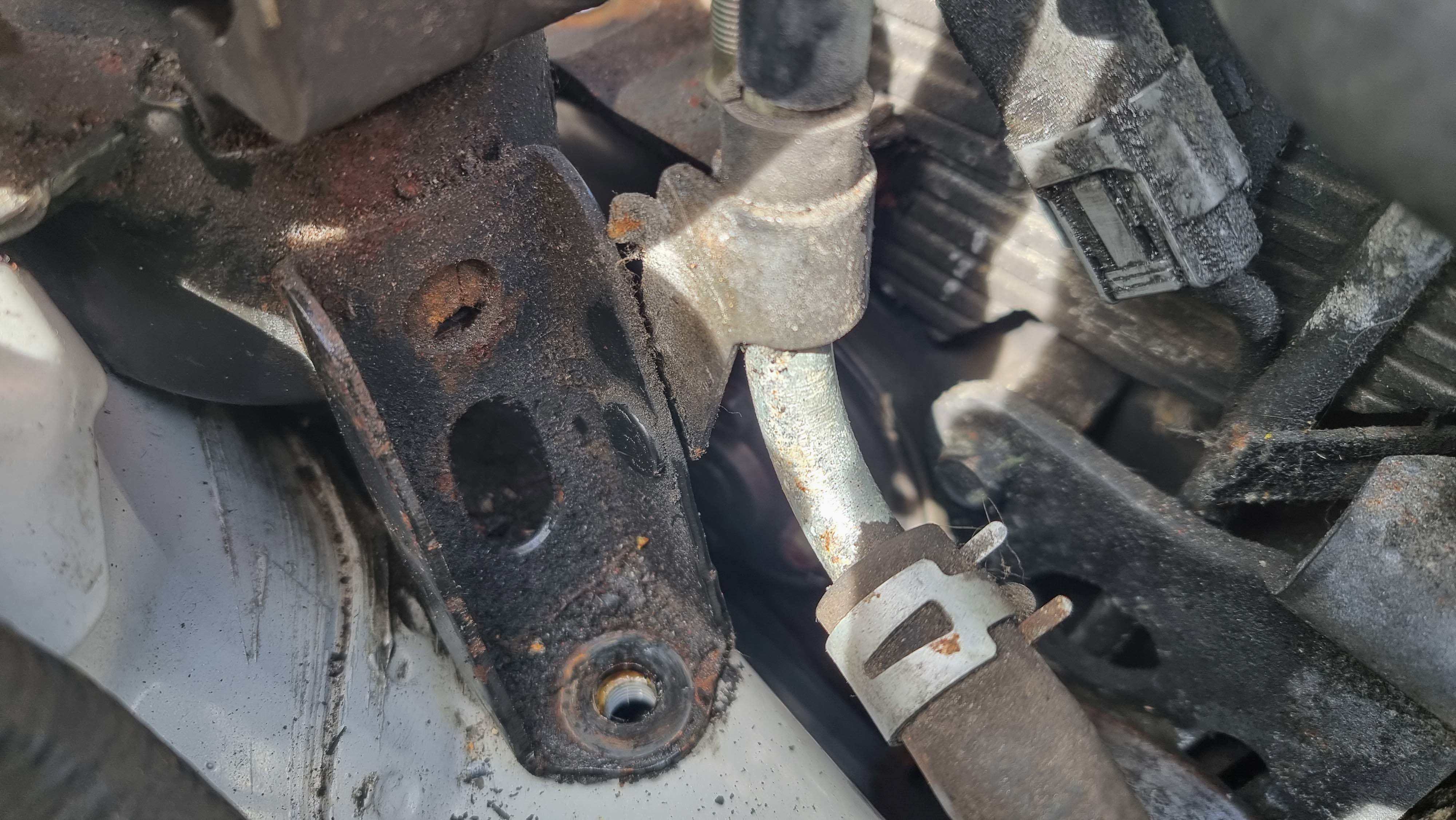
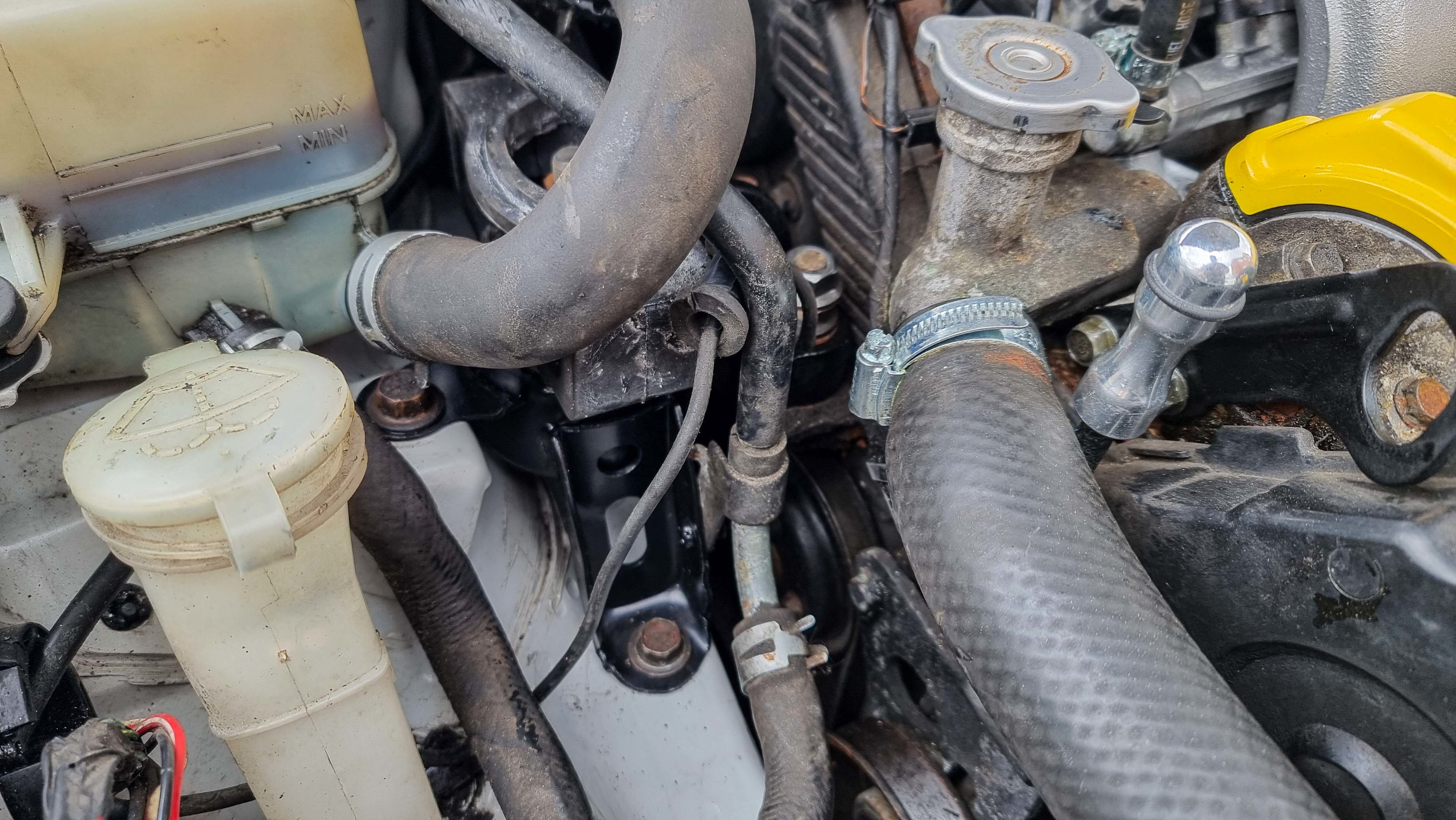
The driver side mount was the next one to look at. With the engine supported with a trolley jack and a piece of wood it was time to loosen the nuts.

There's 4 nuts on the top, one is for an earth strap which sits ontop of another nut.
There's 2 bolts that hold the mount to the chassis. There's also a 10mm nut that holds a bracket onto the main mount.
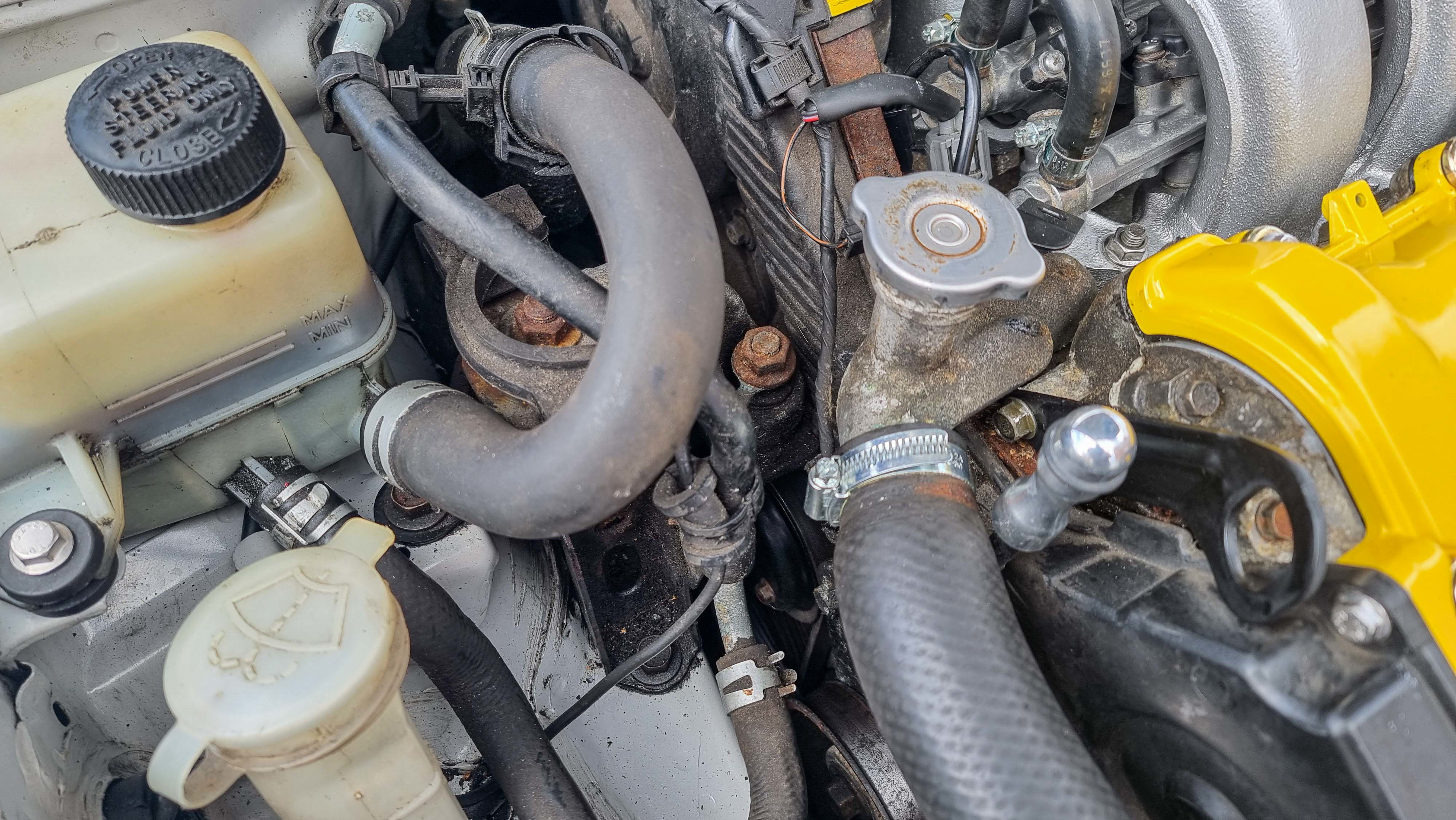
The powder steering reservoir needs unbolting and lifting up and off from the bracket. From here the mount can be removed while navigating under the hose.
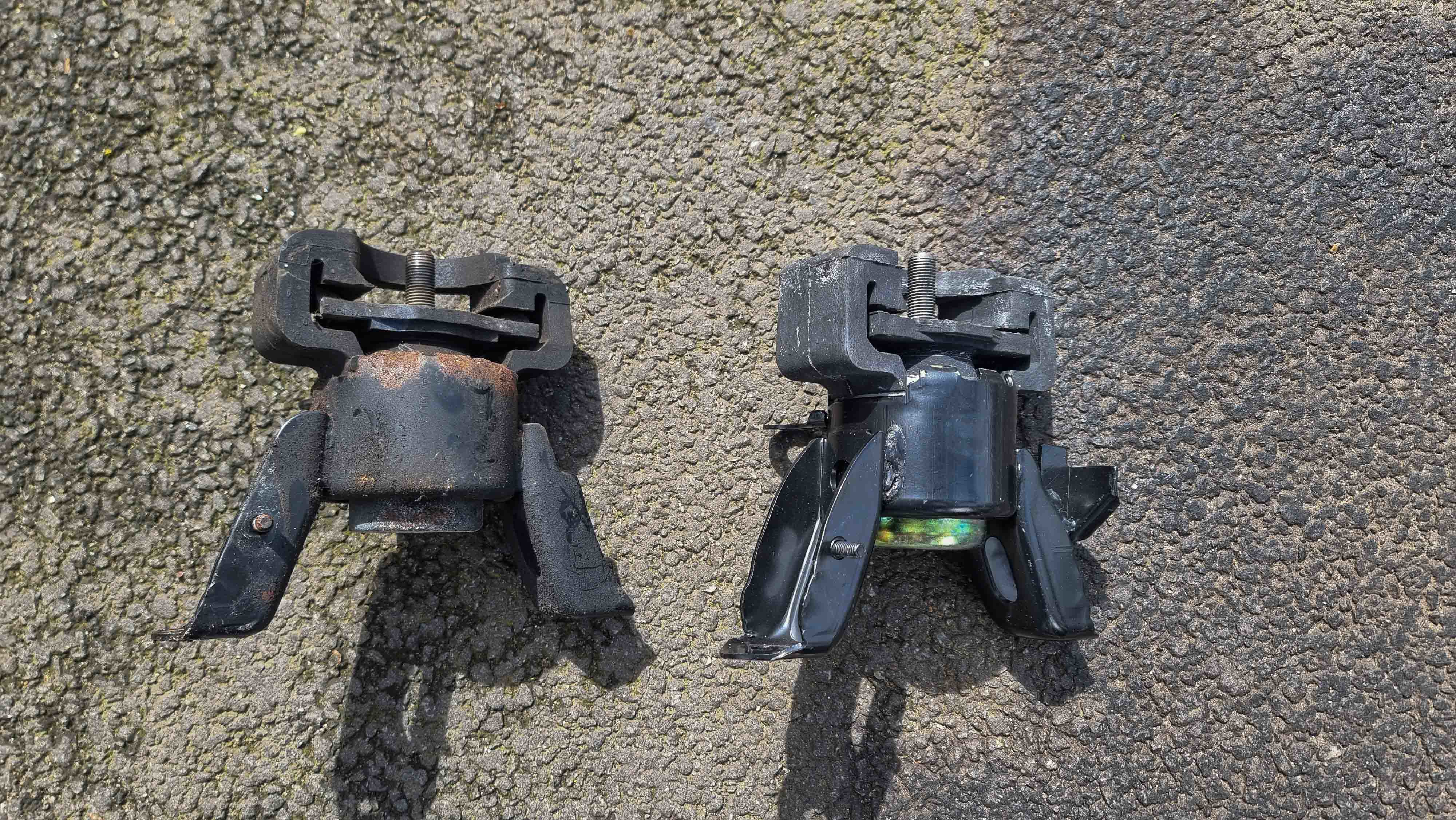
The mounts look pretty identical with a couple of minor differences. The top stud is longer on the new one and there's an additional bracket? on the right hand side which faces the bulk head.

At first thought I didn't think it would line up. But I threaded in the bolts by a couple of turns and they equally tighened up. The top bracket dropped straight on

Unfortunately I still have the knocking noise. I've got front lower ball joints and stabaliser links to change. But I've got a strong feeling it's going to be the rear engine mount. To do that the subframe needs removing because access to the bolts is blocked by the bulkhead.
The next job was something that was being revisited from the engine bay refresh update. You may remember me breaking the check valve and barb on a vacuum chamber which are bolted to the underside of the inlet manifold.
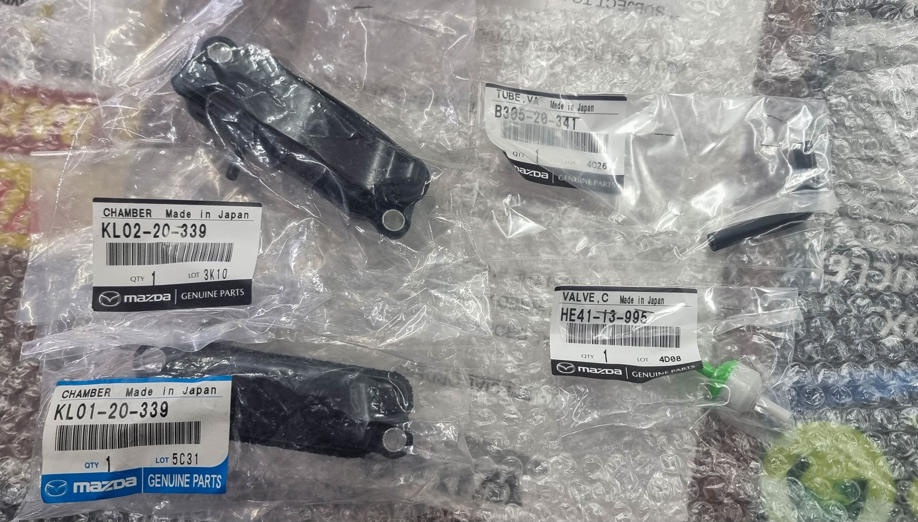
I made an(other) order with Amayama for some replacement parts to fix the issue. I decided to buy both chambers, check valve and the elbow hose.
After the refresh I knew something wasn't right, the car was lacking a severe amount of power (well...what ever is left lol) So I knew it was related to the check valve I got from my work.
It didn't take long to remove the inlet manifold (I'm getting pretty good at doing this now!) to see what was causing me problems.
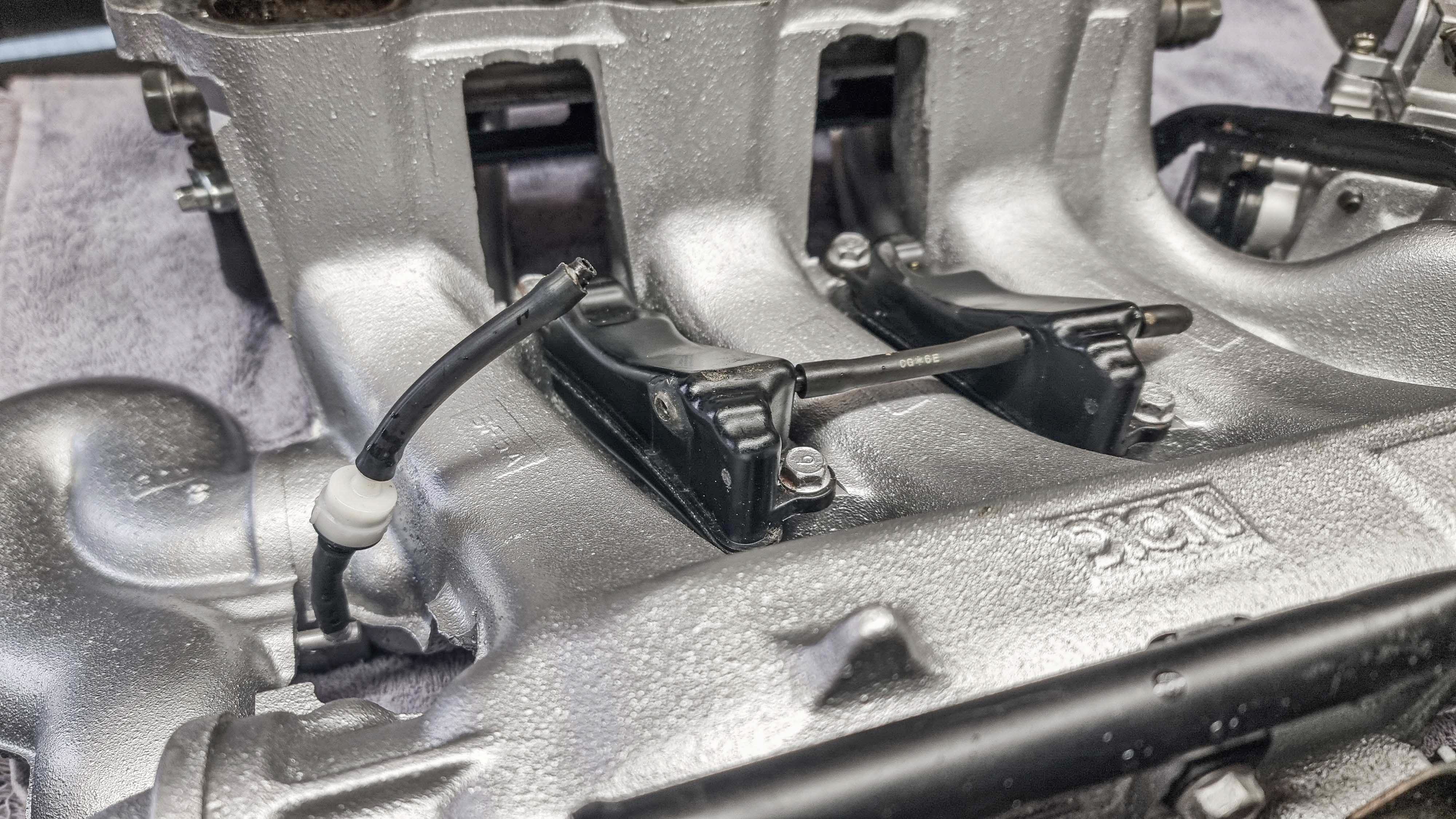
The barb had pulled itself out from the chamber (I already knew the glue had failed from last time), that would explain alot!
It didn't take long to fit the new parts, it's a good job I purchased the other chamber because that barb had snapped off to.
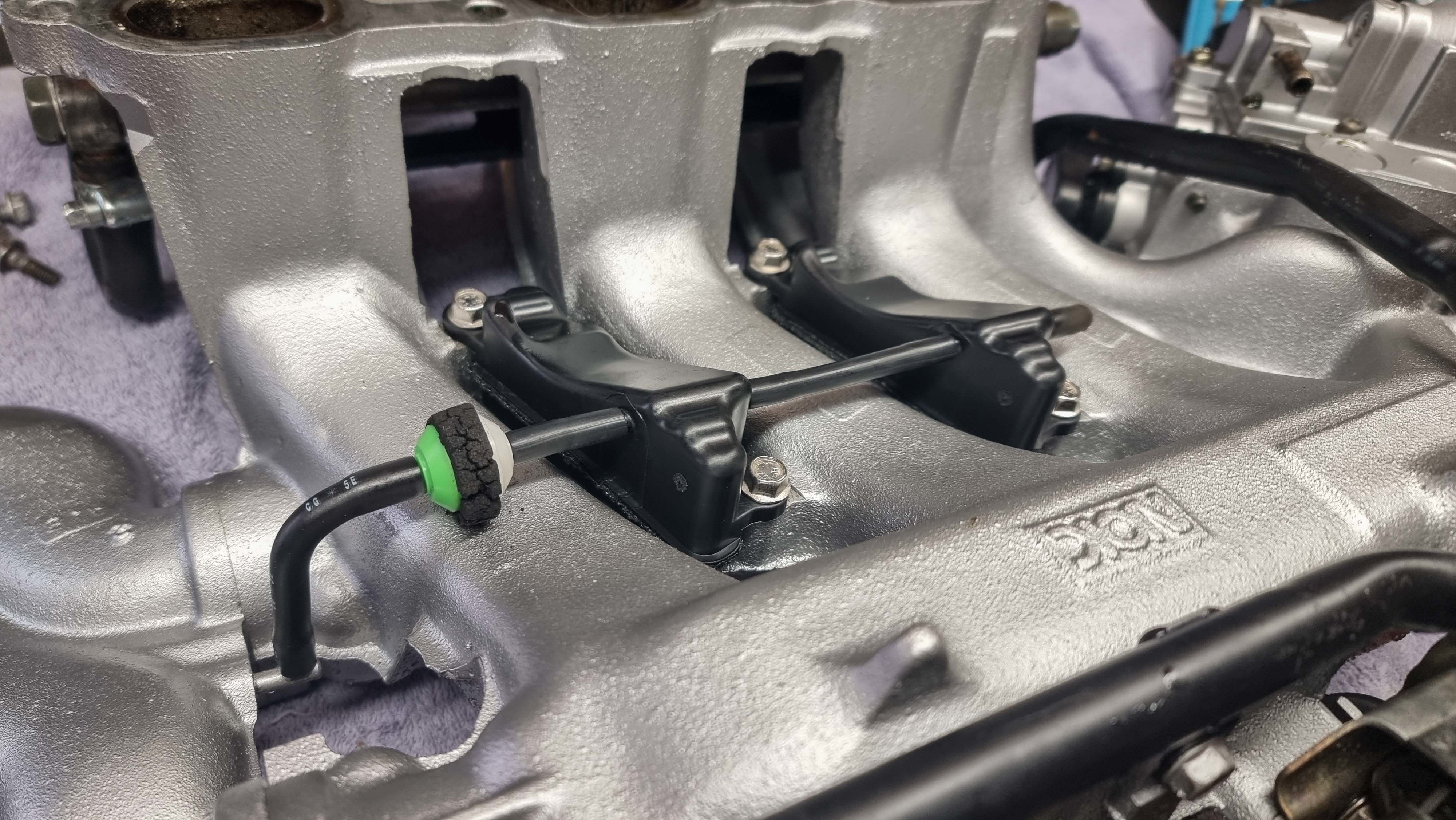
I'm kicking myself for not ordering a new foam buffer ring thing that goes around the check valve, it's just to stop the check valve from rubbing against the inlet manifold. Hopefully this one lasts a little while longer.
With it all back together it was time for a test drive. My face lit up when the VRIS engaged and the car was back to running normal again.
Youtube video can be found here:
https://www.youtube.com/watch?v=sLt9-6Hpxps
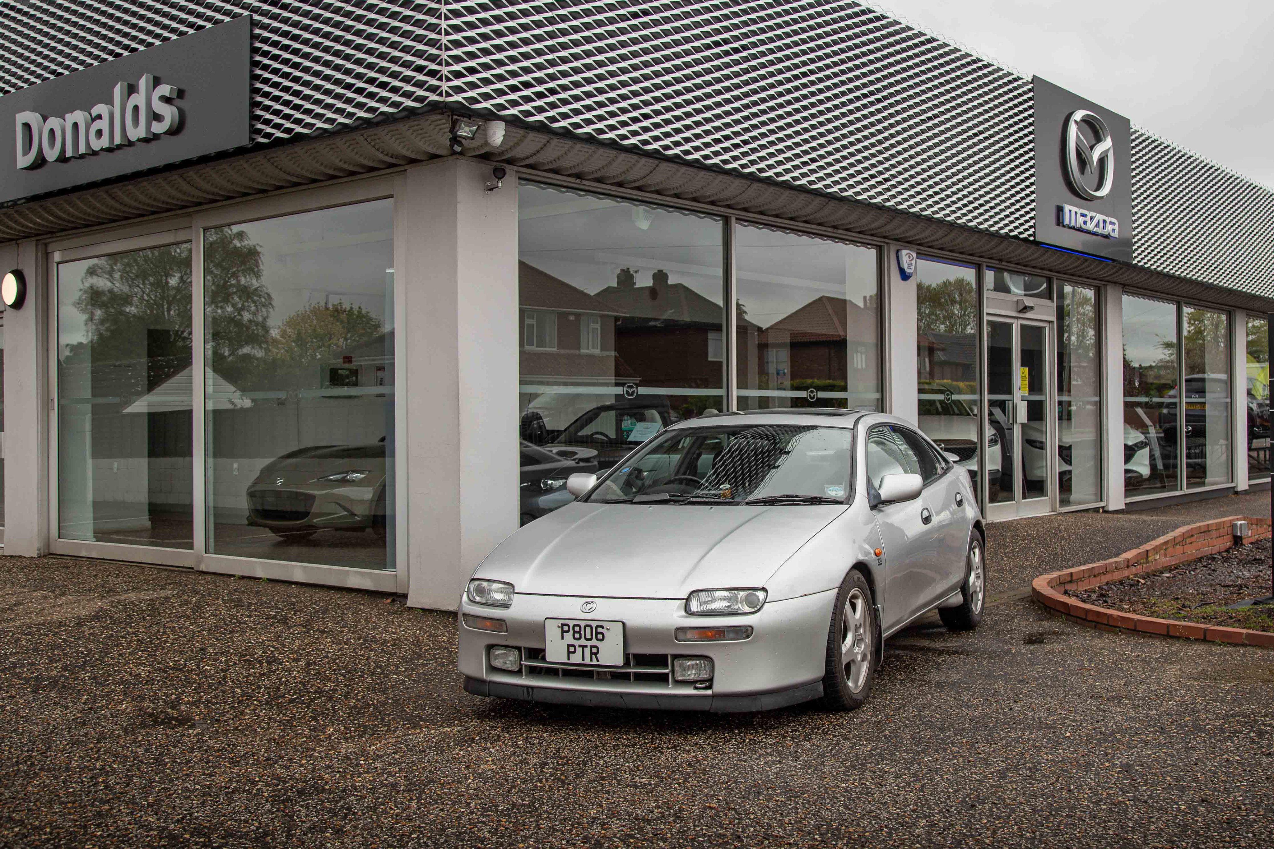
A couple of Sunday's ago I was invited to the local Mazda dealership for a small event they had organised for the 35th Anniversary of the MX5 (or Miata to some readers), it was also the 30th Anniversary of the 323F. The MX5 club were there having a number of cars on display. I did arrive late due to being at my Cars & Coffee event that I organise.
The rain hadn't stopped all morning so alot of people had already left. The event finished at 12:30pm and I waited till everyone had left so I could get some photos outside the dealership.
Fun Fact: The owners manual that I got sent by another member, that car was originally sold at this dealership back in the mid '90s. The staff even recognised the signatures in the service history.
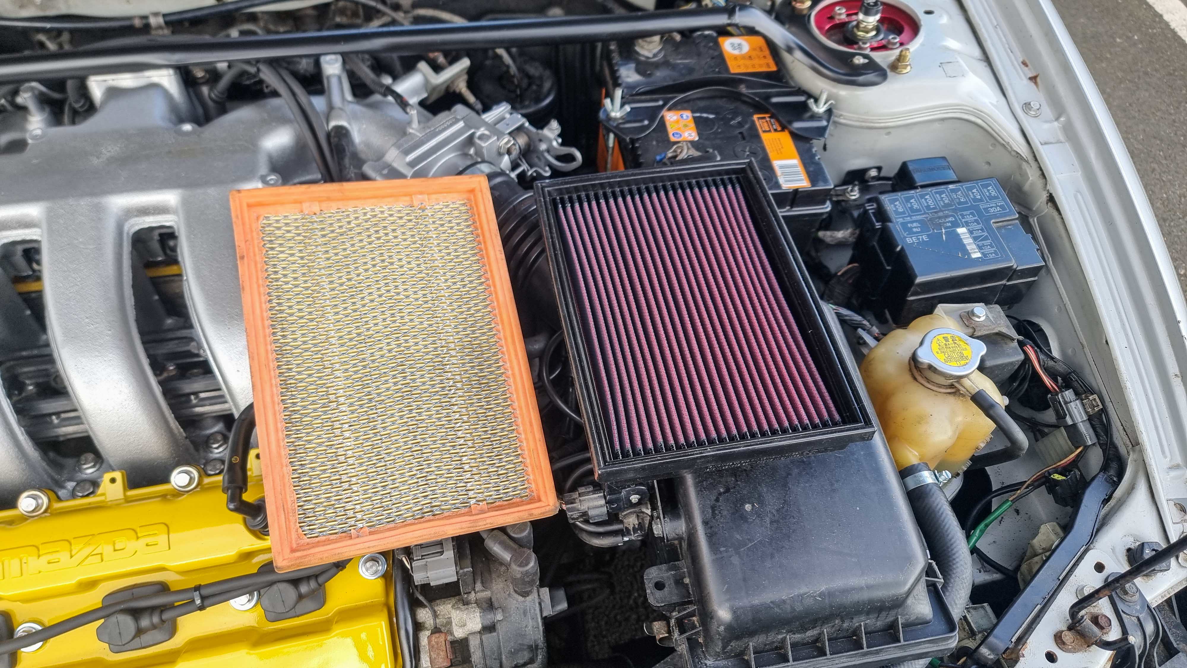
I managed to find a new old stock K&N panel filter. The bag had been opened so chances were high of the oil being non-existant. I ordered a recharge kit (cleaner and oil) and set about re-oiling the filter before installing.
The Youtube video can be found here:
https://www.youtube.com/watch?v=KWYx9-LvPlg
The last part of this update was an interior change. The car came with a steering wheel boss kit so I decided to put it to good use. These cars probably weren't designed for larger people like myself and I'm ashamed to admit that it can be a squeeze getting in and out.
With the battery disconnected and left for a couple of hours I could get to work with removing the airbag. There's x4 10mm bolts holding it on. With the airbag pulled out it revealed the loom, a large blue plug that housed a smaller blue plug and an orange one.

I couldn't unplug the short loom that goes to the clock spring. I followed the wiring back and found another blue and orange plug.
Club member Paul kindly sent me a couple of resistors, I pushed them into the blue plug and taped it up. I wrapped the wiring around the boss and pushed the cover for the HKB boss over the top.
Unfortunately the resistor still put the airbag light on the dash. I'm hoping its from a poor connection, but I didn't have my soldering iron to hand to make a little adaptor. I got the steering wheel bolted onto the hub and went for a test drive.
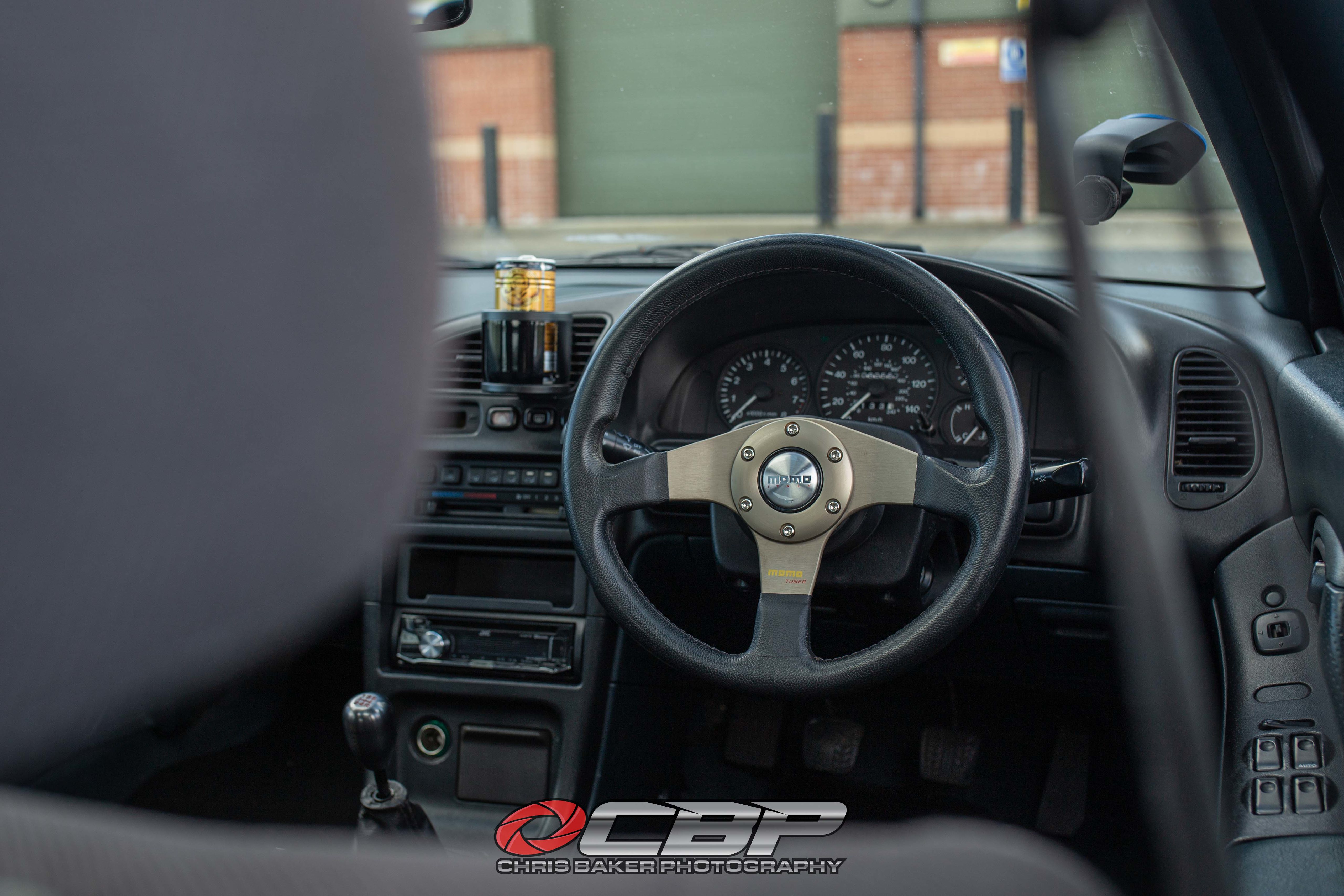
Finding a suitable steering wheel was tricky. The original measures 375mm but most steering wheels seem to be 350mm. I wanted something 90s styled to suit the car better.
After numerous messages to a long list of sellers I finally found this 320mm Momo Tuner on eBay in very good condition.
The youtube video can be found here:
https://www.youtube.com/watch?v=5DyBocEUXoc&t=...
Sorry for the long read, turns out it was a larger update than anticipated.
The next update is a big one, I've been wheel shopping!
While doing the clutch change we swapped over the passenger side gearbox mount. The bracket that bolts to the gearbox is different on the V6 and I so happened to have ordered a 1.5/1.8 mount *eye roll*
Luckily that bracket is on a spindle that passes through the bush mount and is held on by a large nut. The bush itself looked the same so we swapped the bracket over and it all bolted into place.
The reason for the change was because I get a knock when changing gears and sometimes under harsh acceleration. I had purchased all 4 mounts but we only had time to do the one (which made sense because of the clutch change).
Although we did look at the front mount, but the one supplied was incrorrect. Turns out the studs are wider on the V6 model.
The driver side mount was the next one to look at. With the engine supported with a trolley jack and a piece of wood it was time to loosen the nuts.
There's 4 nuts on the top, one is for an earth strap which sits ontop of another nut.
There's 2 bolts that hold the mount to the chassis. There's also a 10mm nut that holds a bracket onto the main mount.
The powder steering reservoir needs unbolting and lifting up and off from the bracket. From here the mount can be removed while navigating under the hose.
The mounts look pretty identical with a couple of minor differences. The top stud is longer on the new one and there's an additional bracket? on the right hand side which faces the bulk head.
At first thought I didn't think it would line up. But I threaded in the bolts by a couple of turns and they equally tighened up. The top bracket dropped straight on
Unfortunately I still have the knocking noise. I've got front lower ball joints and stabaliser links to change. But I've got a strong feeling it's going to be the rear engine mount. To do that the subframe needs removing because access to the bolts is blocked by the bulkhead.
The next job was something that was being revisited from the engine bay refresh update. You may remember me breaking the check valve and barb on a vacuum chamber which are bolted to the underside of the inlet manifold.
I made an(other) order with Amayama for some replacement parts to fix the issue. I decided to buy both chambers, check valve and the elbow hose.
After the refresh I knew something wasn't right, the car was lacking a severe amount of power (well...what ever is left lol) So I knew it was related to the check valve I got from my work.
It didn't take long to remove the inlet manifold (I'm getting pretty good at doing this now!) to see what was causing me problems.
The barb had pulled itself out from the chamber (I already knew the glue had failed from last time), that would explain alot!
It didn't take long to fit the new parts, it's a good job I purchased the other chamber because that barb had snapped off to.
I'm kicking myself for not ordering a new foam buffer ring thing that goes around the check valve, it's just to stop the check valve from rubbing against the inlet manifold. Hopefully this one lasts a little while longer.
With it all back together it was time for a test drive. My face lit up when the VRIS engaged and the car was back to running normal again.
Youtube video can be found here:
https://www.youtube.com/watch?v=sLt9-6Hpxps
A couple of Sunday's ago I was invited to the local Mazda dealership for a small event they had organised for the 35th Anniversary of the MX5 (or Miata to some readers), it was also the 30th Anniversary of the 323F
. The MX5 club were there having a number of cars on display. I did arrive late due to being at my Cars & Coffee event that I organise.The rain hadn't stopped all morning so alot of people had already left. The event finished at 12:30pm and I waited till everyone had left so I could get some photos outside the dealership.
Fun Fact: The owners manual that I got sent by another member, that car was originally sold at this dealership back in the mid '90s. The staff even recognised the signatures in the service history.
I managed to find a new old stock K&N panel filter. The bag had been opened so chances were high of the oil being non-existant. I ordered a recharge kit (cleaner and oil) and set about re-oiling the filter before installing.
The Youtube video can be found here:
https://www.youtube.com/watch?v=KWYx9-LvPlg
The last part of this update was an interior change. The car came with a steering wheel boss kit so I decided to put it to good use. These cars probably weren't designed for larger people like myself and I'm ashamed to admit that it can be a squeeze getting in and out.
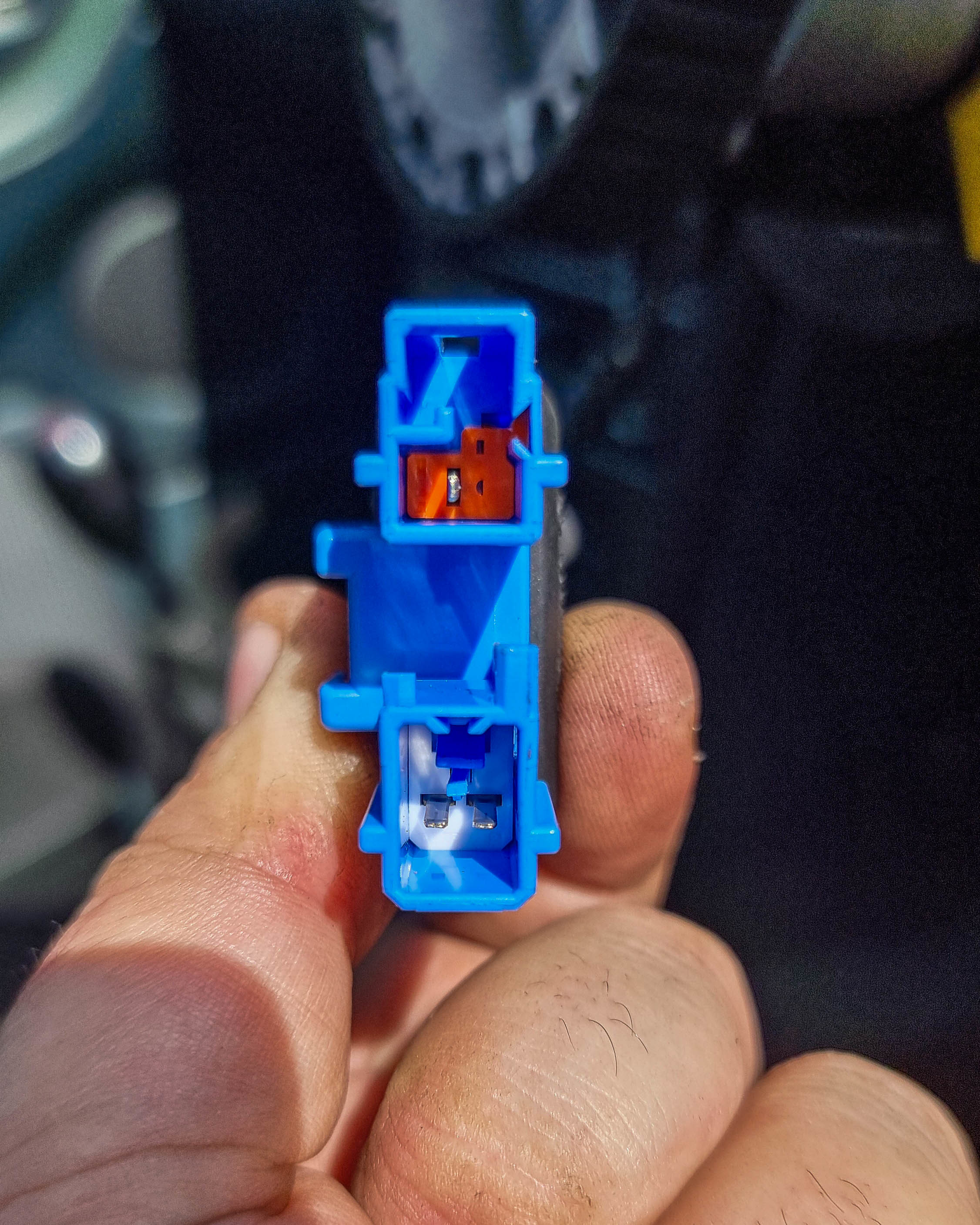
With the battery disconnected and left for a couple of hours I could get to work with removing the airbag. There's x4 10mm bolts holding it on. With the airbag pulled out it revealed the loom, a large blue plug that housed a smaller blue plug and an orange one.
I couldn't unplug the short loom that goes to the clock spring. I followed the wiring back and found another blue and orange plug.
- FOR FUTURE REFERENCE ** The Orange plug with single wire is for the horn. The blue plug with 2 wires are for the airbag
Club member Paul kindly sent me a couple of resistors, I pushed them into the blue plug and taped it up. I wrapped the wiring around the boss and pushed the cover for the HKB boss over the top.
Unfortunately the resistor still put the airbag light on the dash. I'm hoping its from a poor connection, but I didn't have my soldering iron to hand to make a little adaptor. I got the steering wheel bolted onto the hub and went for a test drive.
Finding a suitable steering wheel was tricky. The original measures 375mm but most steering wheels seem to be 350mm. I wanted something 90s styled to suit the car better.
After numerous messages to a long list of sellers I finally found this 320mm Momo Tuner on eBay in very good condition.
The youtube video can be found here:
https://www.youtube.com/watch?v=5DyBocEUXoc&t=...
Sorry for the long read, turns out it was a larger update than anticipated.
The next update is a big one, I've been wheel shopping!
Gassing Station | Readers' Cars | Top of Page | What's New | My Stuff