S3 electric mirror schematics
Discussion


Dear all,
I have a 1990 S3 with electric wing mirrors that does not function. These are not the Citroen type but older "dog ears". I think the mirror are ok, it’s an electrical error.
The problem seems to be that there is no 12V power to the joystick (green cable). The wiring seem to be same as on the wedge type cars with three cables going to the mirror select switch, not 6 cables as the later cars. The joystick has six cables attached.
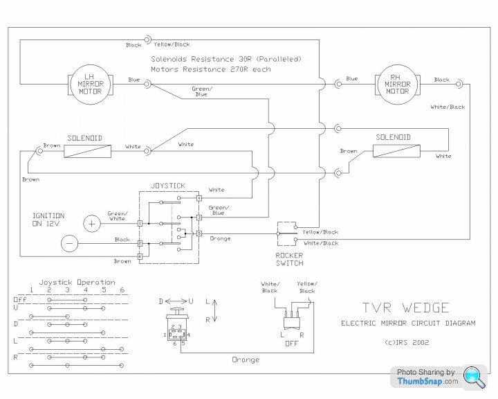
Since the electric mirrors was "special order" back when, they do not pop up on any schematics I can find. The switch and the joystick schematics are available here courtesy of other PH members.
However I cannot find any info on what fuse is used, where the power comes from or what relays are involved.
In my car there is besides the standard fuse/relay central two additional relays and fuses that comes from the wire loom but just lies on the side. I have no idea what they do and they are not described in the OM book.
I can start follow leads but the entire loom is taped and that will take some time. So if someone knows where the mirrors take their power and if there is a fuse only for them that would be much appreciated.
Kind regards
//Rob
I have a 1990 S3 with electric wing mirrors that does not function. These are not the Citroen type but older "dog ears". I think the mirror are ok, it’s an electrical error.
The problem seems to be that there is no 12V power to the joystick (green cable). The wiring seem to be same as on the wedge type cars with three cables going to the mirror select switch, not 6 cables as the later cars. The joystick has six cables attached.
Since the electric mirrors was "special order" back when, they do not pop up on any schematics I can find. The switch and the joystick schematics are available here courtesy of other PH members.
However I cannot find any info on what fuse is used, where the power comes from or what relays are involved.
In my car there is besides the standard fuse/relay central two additional relays and fuses that comes from the wire loom but just lies on the side. I have no idea what they do and they are not described in the OM book.
I can start follow leads but the entire loom is taped and that will take some time. So if someone knows where the mirrors take their power and if there is a fuse only for them that would be much appreciated.
Kind regards
//Rob
Is there any way that you can use this taken from http://www.wedgeneering.co.uk/images/Electric%20Mi... to help trace the fault, you could start off by supplying the correct terminal with a fused supply from the battery and also check the earth is good
I know the chances are that you have this info and have already run a temporary supply.
Just in case
I know the chances are that you have this info and have already run a temporary supply.
Just in case
Edited by Penelope Stopit on Thursday 6th July 20:30
Hi,
Thank you for input. I have searched for info and read most posts but they normally talk about the mirrors and the joystick wiring.
Not much info on how they are fed from the car and if any of the other electric stuff is involved.
It should be enough with the key on, right? No need for the engine to run for the mirrors to work?
I will try to run 12v direct via a fuse tomorrow. However it would be nice to fix the real problem in the power feed.
All info and input much appreciated as TVR wiring is a bit confusing.
Kind regards
//Rob
Recently sorted my mirror wiring out after I took out the days and lost my photos of the wiring. Mine was 6 wires on the joystick and 6 on the selected switch. However, the live feed from the car is a single green wire to the joystick. There's an earth. There too, from memory I think it was the black. The live powers the relays too i.e. the mirror circuit is a stand alone circuit. The joystick is a lot more complicated than it looks the N, S, E and W positions connecting different combinations of the 6 terminals; some positions 2 and others 3 terminals (took me ages to suss out which wires went where as the colours didn't match the mirror wiring diagram I had; Griff mirror wiring from what I remember).
Good luck
N
Good luck
N
Hi,
Thank you for input.
Having mixed up cables must be worse. I do Think my joystick and side switch is factory standard with no loose cables so that should be ok.
Further along the green +12v cable it becomes more cloudy.... I have no idea where it goes. I probably will have to take the fuse central down. Any good ideas how that is attached? Seem to be bolted with two bolts upwards on the rear side.
I also found a 4rth fuse holder that hold s two fuses and seem to be empty. I will have a closer look on Sunday.
Does anyone know what all the unconnected connectors are for? I have 5 different connectors on the wire look that is not connected to anything. Two are single pole round ones. One is 3-pole and one is 4-pole. There is also a multi pool under the dash behind the glovebox. -A bit odd.
Kind regards
//Rob
What I do know is that a green with no trace is a fused ignition supply unless TVR have broken all the rules, if the supply was coming from anything else other than a fused ignition supply it would be green with a trace
Start checking continuity from the green at the joystick to greens entering the fusebox or added fuse holders, I can think of no reason why it would change colour anywhere
Start checking continuity from the green at the joystick to greens entering the fusebox or added fuse holders, I can think of no reason why it would change colour anywhere
Agreed I probably will have to drop the fuse box to see what is going on. I’m pretty certain that the cable loom is all stock so I should be able to follow the cable and find out why there is no 12v power.
One of the problems is that the wire loom is all taped up so you can’t really follow what is going where with the fuse box in place…
I guess the two bolts holding the fuse box goes out into the engine compartment. Are they visible on the “engine side” so I can tighten them later?
One always what to find the “easy way out” but that rarely exist on TVR’s. So I will have to do what I have tried to avoid, drop the entire fuse box. God knows what other failures can follow such maneuver…
I have just changed diff, brakes & hoses, hoses, shocks, ignition, clutch hydraulics, fan, headers, exhaust , seals, bushings and so on so I’m getting pretty used to nothing turning out as expected….
Kind regards
//Rob
sebackman said:
Agreed I probably will have to drop the fuse box to see what is going on. I’m pretty certain that the cable loom is all stock so I should be able to follow the cable and find out why there is no 12v power.
One of the problems is that the wire loom is all taped up so you can’t really follow what is going where with the fuse box in place…
I guess the two bolts holding the fuse box goes out into the engine compartment. Are they visible on the “engine side” so I can tighten them later?
One always what to find the “easy way out” but that rarely exist on TVR’s. So I will have to do what I have tried to avoid, drop the entire fuse box. God knows what other failures can follow such maneuver…
I have just changed diff, brakes & hoses, hoses, shocks, ignition, clutch hydraulics, fan, headers, exhaust , seals, bushings and so on so I’m getting pretty used to nothing turning out as expected….
Kind regards
//Rob
Don't let dropping the fusebox bother you, nothing should go wrong when dropping the box and if something does go wrong it was going to go wrong sometime in the near futureOne of the problems is that the wire loom is all taped up so you can’t really follow what is going where with the fuse box in place…
I guess the two bolts holding the fuse box goes out into the engine compartment. Are they visible on the “engine side” so I can tighten them later?
One always what to find the “easy way out” but that rarely exist on TVR’s. So I will have to do what I have tried to avoid, drop the entire fuse box. God knows what other failures can follow such maneuver…
I have just changed diff, brakes & hoses, hoses, shocks, ignition, clutch hydraulics, fan, headers, exhaust , seals, bushings and so on so I’m getting pretty used to nothing turning out as expected….
Kind regards
//Rob
If you get stuck on tracing that wire you may be able to strip some tape off the loom in several places and give the wire a gentle tug to see if it will pull through the loom a little, if the wire does start to pull through the loom a little you would need to get someone to look for it moving into the loom at the other end when giving it more of a tug through, if it pulls through it will pull back later, sometimes they pull through other times they don't, this would be a last resort if all else fails
Have you a picture of the fusebox and if so can you upload it here?
I didn't answer all your questions
The extra plugs are very likely used for another specification vehicle
There should not be any need to run the engine before being able to operate the mirrors, even if the engine did need to be running the fault you have comes before a engine run control circuit, the fault you have is a missing 12 volt fused ignition supply on the green wire
I earlier mentioned you running a fused supply from the battery to the green wires terminal at the switch so that at least you can prove it will work or not once you solve the green wire mystery. I wasn't suggesting running a fused supply from the battery as a permanent fix, you do need to find and rectify the fault on the green wire
Crossed Posts
Edited by Penelope Stopit on Friday 7th July 20:43
phillpot said:
Penelope Stopit said:
I can think of no reason why it would change colour anywhere
Oh how little you know about TVR's ... 
On a Chim (and others) the engine loom is Rover V8. Where it meets the car loom is a connector with about 20 ways and almost all of them change colour one side to the other.
Steve
sebackman said:
I guess the two bolts holding the fuse box goes out into the engine compartment. Are they visible on the “engine side” so I can tighten them later?
I don't know what your specific vehicle is like, but normally the fuse/relay box and ECU would be attached to a vertical metal plate that is mounted by a couple of bolts through the top of the passenger footwell - you can see the other side of these bolts in the engine bay.Hi
I did take a look today and there are two bolts over the passenger foot well, one vertical and one horizontal.
I will try to take down the fuse box tomorrow. There is definitely something loose up there. Whether is indeed should be loose or not is still to be seen. 
-Will revert with pictures and findings.
Kind regards
//Rob
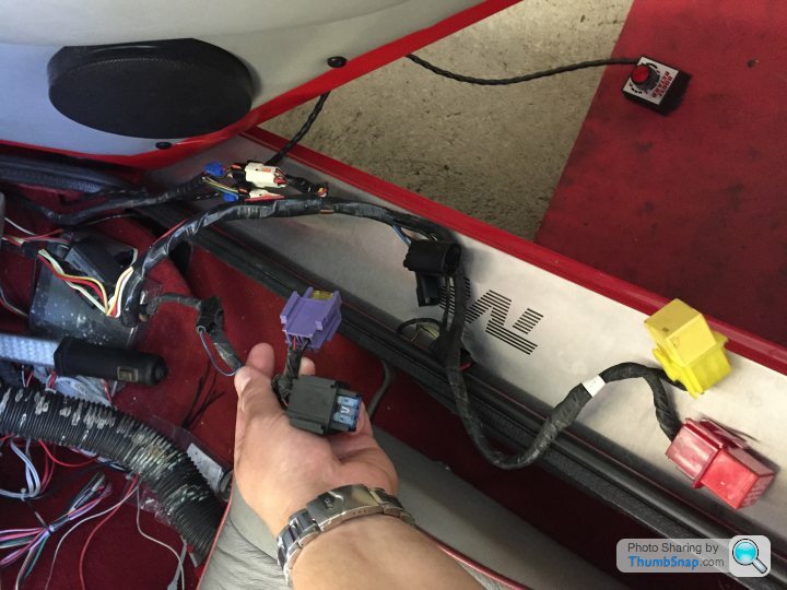
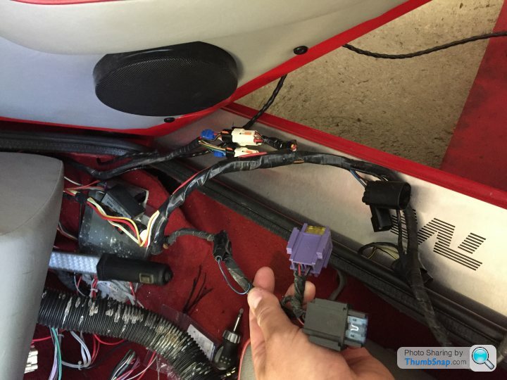
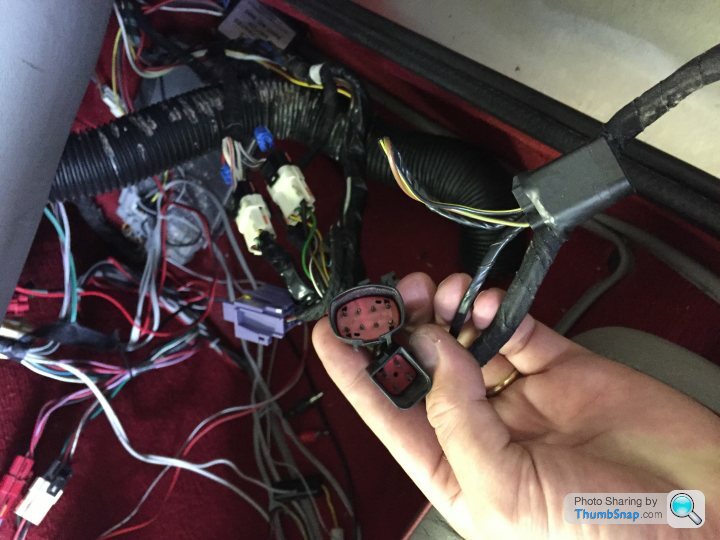
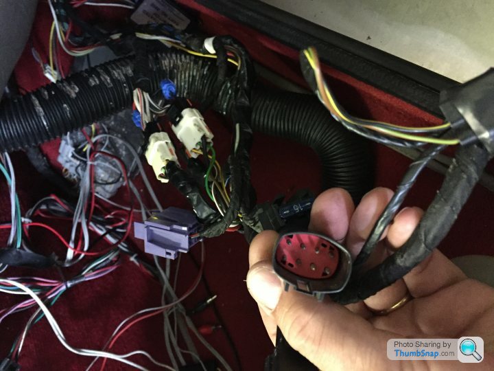
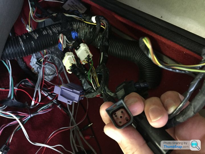
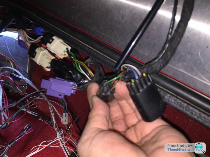
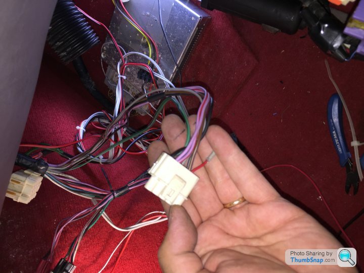
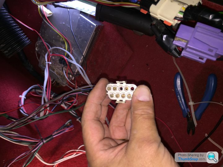
There are 8 not used connectors in the passenger foot well. Here are 7 of them pictured.
1 Black 8 pol with only two poles connected, on the "extra loom"
1 Black with 4 poles with only three poles connetced, on the "extra loom"
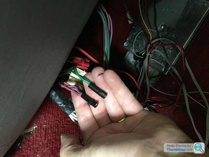
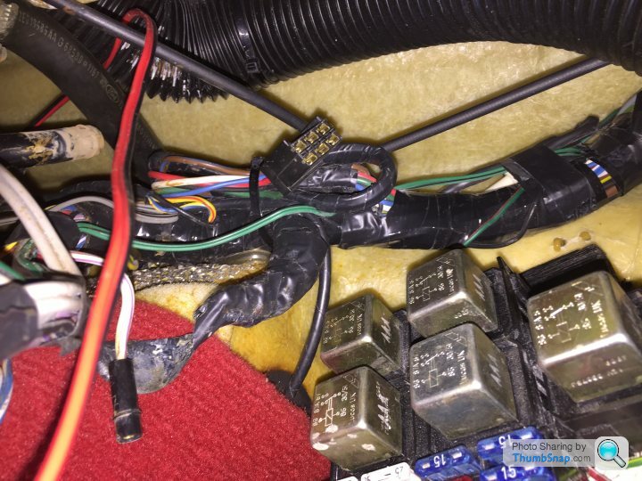
3 round single pole, one with 2 White Cables (visible on the last picture), one with 2 Green cables ( no not the one..) and one with 3 Red and Blue Cables
1 White with 9 poles but only 7 Cables connected (this may be old door speaker wiring not used as new ones are installed). Don't know what the 3 extrea leads are for, maybe power to the radio.
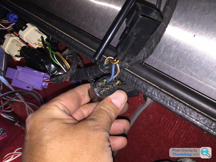
1 Square Black 6 pole up by the fuse box (last picture) with green Cables and not the one I'm looking for.
The 8-th looks like a Lampda contact 3-pin male and comes from the engine compartment but terminates in the passenger foot well.
Beyond that there are several Cables that just seem to be cut and not isolated and some that are cut and actually isolated (with tape).
Very odd cable loom indeed.
I will now take down the fuse box to see where that takes me.
//Rob
1 Black 8 pol with only two poles connected, on the "extra loom"
1 Black with 4 poles with only three poles connetced, on the "extra loom"
3 round single pole, one with 2 White Cables (visible on the last picture), one with 2 Green cables ( no not the one..) and one with 3 Red and Blue Cables
1 White with 9 poles but only 7 Cables connected (this may be old door speaker wiring not used as new ones are installed). Don't know what the 3 extrea leads are for, maybe power to the radio.
1 Square Black 6 pole up by the fuse box (last picture) with green Cables and not the one I'm looking for.
The 8-th looks like a Lampda contact 3-pin male and comes from the engine compartment but terminates in the passenger foot well.
Beyond that there are several Cables that just seem to be cut and not isolated and some that are cut and actually isolated (with tape).
Very odd cable loom indeed.
I will now take down the fuse box to see where that takes me.
//Rob
Gassing Station | S Series | Top of Page | What's New | My Stuff