Misfiring When Warm
Discussion


Hi,
Although this is related to a recent post on electronic ignition, I think it is sufficiently different to justify a separate post.
My 2500 misfires when warmed up and is also sometimes difficult to start when warm.
The problem started a little over two years ago, on MOT day! The fault was diagnosed as no output from the coil. My MOT tester kindly replaced the coil and the problem seemed to be resolved. The car had Neutronic electronic ignition fitted at the time.
I had covered around 1000 miles since buying the car. Some journeys were long and some were taken on hot days. Up until this point there had been no ignition problems.
In January this year, I drove about 2 miles to get petrol. After putting some fuel in, the car wouldn't restart. The RAC came out and checked the car over. Again, it was established that here was no spark (some of the time) when warm. The king lead was unlpugged fron the distributor cap and held close to the rocker cover when cranking. There was power supply to the coil but no HT output. The coil was warm but not excessively hot.
The coil was fairly new so the next suspect was the electronic ignition, which was of unknown age.
I ordered and fitted a Lumenition Optronic kit - module, optical switch, coil and ballast resistor. When fitting I noticed the chopper blade was sitting too low and likely to drag against the top of the optical switch or the mounting screw. I phoned Autocar (Lumention). They asked if the distributor had been rebuilt. I don't know if it has but the chopper and optical switch from the old Neutronic system fitted correctly. Ultimately, they didn't seem too concerned about this.
I finished installing the Lumenition, started the car, tweaked the timing and the engine seemed to run OK. I let it warm up and switched off. It wouldn't restart. Both the RAC and Autocar (Lumenition) suggested running in an extra earth wire. I did this and it seemed to cure the problem.
The coil on the Triumph 2500 engine is mounted to the side of the engine block. I didn't like the idea of this so I mounted the Lumenition coil and module away from the engine.
Since then, I've driven the car a couple of miles around the block, switched off and restarted with no problems.
A few weeks ago, I took it for its first drive in a long time. After about ten miles it started to misfire. This gradually got worse resulting a major loss of power. With feathering the throttle, the car would still drive but only just. If I pressed the throttle at all, the misfire got worse and the car slowed down. It made the 10 miles or so home though.
Back home in the (dark) garage, with the engine running I looked under the bonnet. There were no sparks flying and nothing obviously wrong. The engine seemed to rev freely in neutral but was barely able to pull the car along. The coil and module were both warm but not hot.
On checking the car over (a week later), the battery voltage was 12.5. The voltage at the ballast resistor was about 11. Is a drop of about 1.5 volts after going through the loom, ignition switch and battery isolator switch about right?
I checked the battery switch on its own and it seemed to be losing about 1/3 of a volt. The output from the ballast resitor is about 5.5 volts. I hope the coil runs on 6 and not 9 volts!
The underside of the chopper blade has score marks so it's definitely been dragging against either the optical switch or the mounting screw. If it is dragging against the switch, could this raise the temperature beyond 125 celcius which is its maximum specified operating temperature?
Another possible issue could be where the thin wires from the optical switch exit the distributor cap. They are within a milimetre or two of the cylinder head. Could heat from the engine cause a problem here?
As the battery isolator switch was losing about 1/3 of a volt and it cuts the -ve supply, I thought it likely to have a detrimental effect on the earth. I bypassed the switch and took the car on the same run as a few weeks previously. This time it did the 22 miles without issue. Back in the garage I switched off and restarted it easily. It's too early to say at this stage whether I've found the problem though.
Has anyone else had heat related ignition problems? Does anyone else have a Triumph six cylinder engine with Lumenition or Neutronic ignition and a battery isolator switch?
Apologies for the length of this post.
Any ideas or suggestion swould be appreciated.
Thanks,
Chris
To give you something to think about regarding volt-drops...0.75 Volts volt drop is the maximum to work to when checking for the volt-drop between battery positive and the starter motor positive during cranking, bearing in mind that the starter could be drawing 250 to 350 Amps when operating.
0.25 Volts volt-drop is the maximum to work to when checking for the volt-drop between battery negative and the starter motor body during cranking, bearing in mind that the starter could be drawing 250 to 350 Amps when operating.
Your volt-drops....0.333 Volts volt-drop across the Isolator switch is a fail - The switch is faulty, bearing in mind the above....I take it you are measuring 0.333 Volts volt-drop across the Isolator switch when the ignition is on and the starter is not being operated.....There will be a big volt-drop across that switch when cranking and that will show at the ignition system and could well cause it to fail
Moving on, in addition to the above isolator switch problem you have also measured a volt-drop of 1.5 volts at the ignition supply to the ballast resistor and that is a fail......Depending on the resistance of the ignition coil and they do vary a bit ballasted and unballasted....lets use 2 figures for 2 calculations.....coil = 1.5 Ohms and coil = 3 Ohms....Amps = V ÷ R....Amps = say 12 volts ÷ 1.5 Ohms and 3 Ohms.....Amps drawn by a 1.5 Ohm ballast coil when cranking = 8 Amps....Amps drawn by a standard 3 Ohm coil = 4 Amps
I haven't got involved with taking into account the battery voltage drop when cranking for the above calculations as I don't want to complicate this too much for you but do give this some thought as there could be a close to 2.5 Volts volt-drop at the battery when cranking and this is why ballast resistor circuits are used because they compensate for the battery volt-drop when cranking by applying a higher voltage to the coil during cranking
Going back to those above calculations and they are only examples but could well match up with your ignition circuit.....Your ignition supply from the ignition switch to the ballast resistor very likely has no more than 8 Amps being drawn through it and that is during cranking, once started that current draw will very likely drop to approximately 4 Amps which is the same as a standard 3 Ohm coil (ballast coil is 1.5 ohms)
The 1.5 Volts volt-drop you measured at the ballast resistor supply from the ignition switch included 0.333 Volts volt-drop across the Isolator switch, taking this into consideration the true volt-drop at that ignition supply is 1.167 Volts and this is a fail
I have included thee above calculations so that you can understand what you need to be aiming for. The ignition switch and the supply to it and from it to the ballast resistor need to carry a maximum current of approximately 8 Amps with next to no volt drop, 8 Amps is a relatively small load that over a distance of 2 to 3 meters through a good correct size cable will not be problematic and I doubt your ignition switch to ballast resistor cable is that long
If i was rectifying this ignition volt-drop problem I would be using standard 28/030 automotive cable that will carry 17.5 Amps as that will cut the volt-drop down to next to nothing,********** 14/030 cable has a maximum current rating of 8.75 Amps which is very close to what your ignition circuit could be drawing and obviously the lighter the cable the higher the volt-drop over distance **********
The ignition circuit you are working on may well be using 14/030 cable which is borderline
Also bear in mind that the supply cable to the ignition switch must be good and heavy enough to supply all ignition circuits plus the ballast resitor with a minimal volt drop and that the ignition switch contacts are good and there is very little volt-drop across its contacts
You will need to also check all connections in the circuit for volt-drops unless you rewire the ignition switch to ballast resistor circuit in which case don't break the new cable that you run unless you must (Volts don't like connectors)
The below figures will show how far out your circuits are, don't take anything as set in stone as there are many variables but these figures are going to be very close to what you should be able to achieve...Taken from http://www.fluke.com/fluke/uses/comunidad/fluke-ne...
0.00V across a connection
0.20V across a wire or cable
0.30V across a switch
0.10V at a ground
Very small volt-drops aren't they
Hi,
Thanks for your reply. I appreciate the time you've taken to give such an informative response. There is a lot for me to take in and hopefully learn from in your answer.
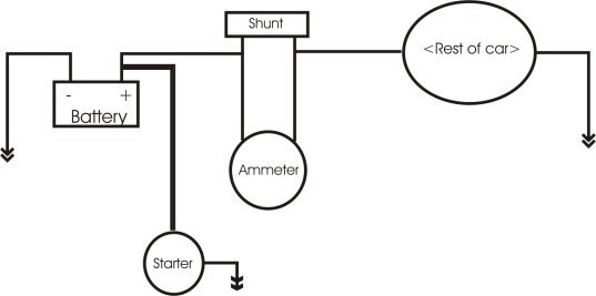
One thing that particularly puzzles me though is if the starter draws several hundred amps and the ammeter in the car only reads between -45 and +45, how can the two work together without causing problems?
Thanks again,
Chris
Thanks for your reply. I appreciate the time you've taken to give such an informative response. There is a lot for me to take in and hopefully learn from in your answer.
One thing that particularly puzzles me though is if the starter draws several hundred amps and the ammeter in the car only reads between -45 and +45, how can the two work together without causing problems?
Thanks again,
Chris
Hello, I have just thought of something important for when you are checking what voltage there is at the ballast resistor supply in terminal and the coil supply in terminal from the ballast resistor when the key is in the ignition on position
You may be unaware that thee above supply cables are not under any load until the engine is running and the coil is being switched by the electronic ignition
What you need to know is what voltages you have when the circuit is under load (drawing current), voltages measured when a circuit is not under load mean nothing, do the following....
1) Mark the electronic ignition control unit cables so that you don't mix them up and disconnect them from the ignition coil, be sure that the supply cable from the ballast resistor to the ignition coil is left connected to the ignition coil positive terminal
2) Using a length of suitable cable (size 28/030 is good) as a jumper lead, earth the ignition coils negative terminal to the battery negative or engine block negative
3) Switch the ignition on and measure what voltages are present at the supply into the ballast resistor and the supply at the ignition coil
What you are doing above is testing the circuit under it's running load and not when it's open circuit as it is when connected through the electronic ignition
Don't leave the ignition on for more than 15 seconds at a time and allow the coil and resistor to cool down in-between tests
Have fun, good luck in finding the volt-drops
All good advice.
Couple of qu's..
Is the electronic ignition control module being fed from a direct ignition supply & being grounded to the chassis / block through a dedicated connector? Most aftermarket type hardware doesn't like low voltage operation & you're on a losing streak if you're starting at a ballast resisted level with the sort of volt drops you are seeing.
It might be worth considering using a relay as a load reduction device across the main ignition circuits, that way you can minimise the drops in the key circuits.
You've not mentioned spark plug leads or spark plugs. Is that because they have been replaced? Virtually all elec ignition systems require suppressed plugleads & resistor type plugs to cut down on radiated electrical emissions. It is possible that you have a plug and/or lead breaking down which will keep on resetting the electronic ignition. It's probably less likely than voltage induced problems but owing to the ease of swapping plugs & leads worth mentioning.
Another thing worth looking at is the tacho - if that or its associated wiring has a problem then it could be interfering with the ignition side of things (not sure how it's wired on the 2500, sometimes they can be disconnected at the coil end).
Failing that there are always points & condensers!
Stew
Thanks both for the further replies.
Penelope Stopit - is it normal for the ammeter to read around -15 when cranking? I'm hoping that this is merely showing that the batttery is discharging. When the engine fires, the reading goes over to the positive for a few seconds and then settles at around 0.
I'll try to run the tests you suggested when I get a chance.
Stew - the electronic ignition is using the supply from the wiring loom (if that's what you mean). I have run an extra wire from the module earth wire to the chassis. I have also run a wire from the same point on the chassis to the battery isolator switch.
Using relays to connect to the battery and bypassing the loom might be worth considering. Similarly using points and a condensor would be an option if I can't sort this. I have read though that the quality of points is poor these days. Also it would be a shame to use points after spending £200+ on new Lumenition.
As for plugs and leads, I changed them a coupe of years ago and have only covered a small mileage since. The car completed a 22 mile run recently with the battery isolator switch bypassed and there were no issues.
Thanks again both,
Chris
Yes that 15 Amps discharge when cranking is a combination of coil and more so starter motor solenoid current draw
You will find the volt-drops as there is no hiding place for them and you will easily fix them once found, the worst scenario will be the fitting of a new ignition switch if yours is at fault
Relays are great for taking the load off switches but do keep well away from them for supplying the coil....a good ignition switch will supply the correct voltage for many years, it is very bad practice to wire a relay into the coil supply circuit
One thing to remember when working on volt-drops......when you find a volt-drop in a circuit and carry out a fix, this doesn't mean that there are no more volt-drops in the circuit, check the circuit all the way through from start to finish and fix any volt-drops that you may find during your journey
Edited by Penelope Stopit on Monday 28th May 15:09
I'm not sure where the comment about supplying coils via relays being bad practice comes from? If it's whetting current you're referring to (or a lack of it) then supplying other loads via the same relay fixes that, even an oil pressure warning lamp bulb will give sufficient current to keep the contacts clean. If it's inrush then an appropriately sized relay will cope with that without issue - most electronic ignition systems are designed in such a way as to avoid the coil being switched without some form of signal input (something which points clearly can't do). Pretty much anything remotely modern uses relays for all power loads too, there is a move towards using silicon to switch but this has its own issues & in the case of inductive loads requires very good understanding of the transient behaviour of the load across the entire operational range. Relays will generally take whatever you throw at them & keep pulled in down to very low voltages.
Stew.
Stew.
StewB_v6 said:
I'm not sure where the comment about supplying coils via relays being bad practice comes from? If it's whetting current you're referring to (or a lack of it) then supplying other loads via the same relay fixes that, even an oil pressure warning lamp bulb will give sufficient current to keep the contacts clean. If it's inrush then an appropriately sized relay will cope with that without issue - most electronic ignition systems are designed in such a way as to avoid the coil being switched without some form of signal input (something which points clearly can't do). Pretty much anything remotely modern uses relays for all power loads too, there is a move towards using silicon to switch but this has its own issues & in the case of inductive loads requires very good understanding of the transient behaviour of the load across the entire operational range. Relays will generally take whatever you throw at them & keep pulled in down to very low voltages.
Stew.
Yes I appreciate that many modern day cars use elecronic switching and they have been tested and proven by time and number of operations but....a vehicle fitted with a key operated ignition switch from new will not require a relay to improve its circuitStew.
I am an out and out lover of relays and when I die I wish to come back to this planet as a relay, I love how much can be achieved with relays but....if there is one circuit that shouldn't be relayed it is the coil supply circuit, any other circuit being problematic due to a relay or its relay wiring can soon be fixed.....
When a relay or its controls supplying an ignition coil fails there is an instant stopping of the engine and this has been known to cause the loss of life
The fact that manufacturers may be using relays or electronics to power ignition coils doesn't mean that it's good practice, manufacturers often get lost in their electrical design work, it has now got to the stage that cars are so electrically complicated that they do often fail to function correctly and this is all down to costing of the manufacture or having a gadget that no other manufacture has in the hope of that gadget selling more cars
If it was up to me to decide what manufacturers can and can't do with their vehicles electrical systems, the majority of manufacturers would have had to spend more money on electrical design work going back to many years ago. Below is an example
There is no way that manufacturers should have been allowed to produce vehicles with an electric fuel pump circuit that didn't have a built-in fuel pump supply override circuit should the fuel pump relay fail for whatever reason
Perhaps you now understand my reasoning, relays and electronics are great but still have their limitations, unfortunately motor manufacturers seem to have taken a step backwards in many ways
Edited by Penelope Stopit on Monday 28th May 21:05
Gassing Station | TVR Classics | Top of Page | What's New | My Stuff