TVR S1 won't run on after firing up
Discussion


[quote=Blue 30
Just as a point of info, the 6 wire module as used on the 2.8 also adds a fixed amount of ignition retard during cranking.
TerryB.
[/quote]
That would explain the black and green wire going from the Duran park unit to the starter solenoid.
The main ignition supply is actually a bit unusual in that it comes via fuse (a) and goes through the tachometer. Apparently some Rover tachometers worked in the same way, it took me a lot of time to work that out ! The very quick and simple test I would do before swapping more components out would be take a wire from the battery positive to the positive connection on the coil. You need also to put the original connection back onto the coil as that is how you get power to duraspark module (via the ballast resistor on the white core).
I had a high resistance at the fuse holder (a) and had to replace it with an inline unit.
DO NOT LEAVE THE WIRE ON THE COIL IF THE ENGINE IS NOT RUNNING FOR TOO LONG AS YOU WILL BURN IT OUT. A couple of minutes will be fine.
Green V8s. Thanks, Regarding the voltage from resistor wire to the coil, I am going to check that voltage out again tonight.......
We have tried with that resistor wire removed and replaced by a short length of wire with two bullet connectors.
We have tried the above experiment with both the TVR coil and the one borrowed from my V8 Land Rover.
With regards to connections to the DuraSpark module, I have all the connections that are on the circuit diagram, as loaded by Penelope Pitstop (thanks PP, that's as my copy of the 'bible') plus a separate temporary 'crocodile' connection from the module body direct to the battery negative terminal, employing a 'jump lead', just in case
We have tried by-passing the Tacho supply by connecting a lead direct to the battery keeping the connections to the coil as well
I've 'won' a used 'working'module on e bay so hope to get that next week. Fingers crossed!!!!
I cannot believe the help I am getting from the community for which, I really must, Thank You All......
I think if you have provided power to the coil then I'd now be looking at the duraspark unit as well. Forgive me if I'm going over old ground again but how did you decide that you weren't getting a spark ? Have you proven the king lead and rotor arm/distributor cap ? The rotor arm has a crude centrifugal rev limiter device which may be breaking the HV circuit ?
I think if you have provided power to the coil then I'd now be looking at the duraspark unit as well. Forgive me if I'm going over old ground again but how did you decide that you weren't getting a spark ? Have you proven the king lead and rotor arm/distributor cap ? The rotor arm has a crude centrifugal rev limiter device which may be breaking the HV circuit ?
Just another thought. I know we've been on about the DuraSpark module for a while now. But don't forget that the DS unit is basically an amplifier. The trigger is the Hall Effect components inside the distributor, and if that isn't sending the pulses out to the DS module, then it won't have anything to amplify... IE. No sparks !
TerryB.
TerryB.
Here I sit with dirty hands and a beer.....It was the DuraSpark unit . I don't know how they vary but I just got a random one off E bay.
However note........ In the TVR Bible, run is shown as wired to the white and start is wired to the red. On most modules, it seems, and the one in bought, start is the white wire and run is the red wire out of the module
Still some things to sort as the power off the high torque starter motor I have installed is, for some reason low so, as the draw from the WOSP starter is much lower than standard I am going to wire the start supply from the solenoid activation side of the circuit. (By the way the WOSP starter, for £200 is awesome)
I'm going to splash out on a new tailor made module for the cologne 2.8 engine.
Thank you so very much everyone for bothering to take up your time, giving me so much help and advice
The old girl can now progress to her new lease of life
If you mean that the contact in the starter solenoid isn't giving you a good voltage to the coil when cranking -
There are solutions to your problem and I or others here will be able to go through them with you
First you need to post back here and confirm that you are planning to incorrectly wire the circuit
If you have already wired the circuit incorrectly......the resistor should now be overheating and the voltage at the coil will be too low
- **DON'T**** go any further with your plan of picking up a supply from another solenoid terminal to the coil
There are solutions to your problem and I or others here will be able to go through them with you
First you need to post back here and confirm that you are planning to incorrectly wire the circuit
If you have already wired the circuit incorrectly......the resistor should now be overheating and the voltage at the coil will be too low
Trefhead said:
the power off the high torque starter motor I have installed is, for some reason low
Can you explain what you mean by that? I guess you are referring to the voltage measured at the starter motor windings while cranking, but it is unclear.If you connect the switched ignition to the solenoid terminal as you seem to be describing, the solenoid will draw power from the ignition circuit. Probably not enough to actually operate the solenoid, but enough to overload the ignition circuit. If the ignition circuit was able to supply enough current, this would operate the starter as soon as you switched the ignition on.
I don't think I explained myself properly. Yes I do understand what you are saying
When you buy the WOSP starter motor for a cologne engine they add a switched take off on the top for the start ignition circuit which is activated by the starter solenoid actuator circuit.
For some reason, on test, it only gives out 8.64 volts and it should be battery voltage.
This supply does not go through the resistor blue wire but direct to the coil. It is isolated when the starter actuator circuit is turned off.
My proposal is to take the coil supply, (during starting procedure only), from the supply cable from the key switch start position to the starter motor solenoid actuator, or I could take it from the switched side of the starter motor supply (ie the heayy cable after the solenoid contacts and before the starter motor)
Both sources would not be live except when the start position is selected on the key
Trefhead said:
I don't think I explained myself properly. Yes I do understand what you are saying
When you buy the WOSP starter motor for a cologne engine they add a switched take off on the top for the start ignition circuit which is activated by the starter solenoid actuator circuit.
For some reason, on test, it only gives out 8.64 volts and it should be battery voltage.
This supply does not go through the resistor blue wire but direct to the coil. It is isolated when the starter actuator circuit is turned off.
My proposal is to take the coil supply, (during starting procedure only), from the supply cable from the key switch start position to the starter motor solenoid actuator, or I could take it from the switched side of the starter motor supply (ie the heayy cable after the solenoid contacts and before the starter motor)
Both sources would not be live except when the start position is selected on the key
No please stop, this will turn bad on youWhen you buy the WOSP starter motor for a cologne engine they add a switched take off on the top for the start ignition circuit which is activated by the starter solenoid actuator circuit.
For some reason, on test, it only gives out 8.64 volts and it should be battery voltage.
This supply does not go through the resistor blue wire but direct to the coil. It is isolated when the starter actuator circuit is turned off.
My proposal is to take the coil supply, (during starting procedure only), from the supply cable from the key switch start position to the starter motor solenoid actuator, or I could take it from the switched side of the starter motor supply (ie the heayy cable after the solenoid contacts and before the starter motor)
Both sources would not be live except when the start position is selected on the key
Ok you have explained it better now but it is as what I originaly thought
You can't take a crank supply directly from those terminals as they are to earth through the solenoid windings or through the motor when they aren't live, this will overheat the resistor and also drop the supply voltage from the resistor to the coil very low
Do you want the correct way of doing it without having to take the starter off to repair the solenoid caps contact?
Trefhead said:
For some reason, on test, it only gives out 8.64 volts and it should be battery voltage
Just in case there is a mistake being made when you are testing the above voltageThe voltage at the starter ignition coil contact should not be battery voltage, the voltage at that contact when the starter motor is operating should be very close to the voltage at the solenoids battery terminal
Bear in mind that there is a big drop in voltage to the solenoids battery terminal when cranking. If using a fully charged known to be good battery, the voltage at the solenoids battery terminal may well drop to around 9.5 volts
If cranking the engine over with a bad or low battery the voltage at the solenoids battery terminal may well drop lower than 9 volts
The idea of the ballast resistor circuit with a 9 volt coil is to compensate for the above volt drop, what this circuit does is ensure that there is 9 plus volts at the 9 volt coil when cranking
Reading the above where I comment the voltage at that contact when the starter motor is operating should be very close to the voltage at the solenoids battery terminal I do so because the 200 to 300 amps being drawn through the solenoid contacts does arc them up and that can create a small volt drop between the solenoids battery terminal and the solenoids ignition contact, even if this small volt drop was as big as 0.5 of a volt there would still be 9 volts or more coming from the solenoid ignition contact and that is good enough to serve its purpose
Trefhead said:
Thank you. (Sorry for delay in response)
I do get what you are saying.
I was basing my premise on lines on the wiring diagram not on knowledge
Much appreciated
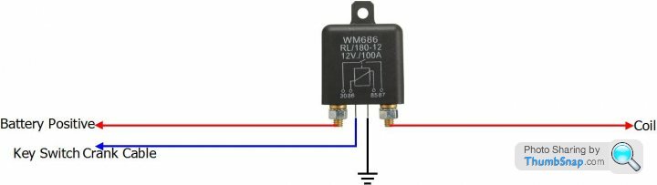
I have ordered the relay
cheers
I checked back here several times a day in the hope that you revisitedI do get what you are saying.
I was basing my premise on lines on the wiring diagram not on knowledge
Much appreciated
I have ordered the relay
cheers
All's well that ends well
Using a relay is a simple good fix

Hi. I’ve been on holiday. Phew. Does seem to be running ok without load (she is not drivable yet still rebuilding her)
I’m still fascinated by the wiring to the duraspark unit (it’s a blue retainer unit, type 2, six wire)
The TVR bible wiring diagram (see previous reply) to my understanding, shows the ‘start’ circuit via red wire and ‘run’ circuit via the white wire.
Internet searches indicate the white wire is the one that adjusts the timing by 10 degrees to assist starting., so the red one is ‘run’
Have I got it wrong? Do I misunderstand the wiring diagram ?
Gassing Station | S Series | Top of Page | What's New | My Stuff