Lambda / oxygen sensor wiring loom
Discussion


Hi all,
It's now time for me to ask your help.
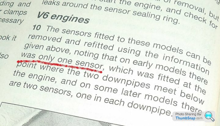
My 1992 S3C has been decatalysed (I don't know when). Catalytic converters were removed with the short exhaust manifolds. Long non-cat manifolds were installed with lambda nut welded on. Genuine lambda sensors are screwed on it. I'm pretty sure that there are the genuine one because they are Bosch brand, with the correct number, and the Ford plastic 3-pin connector.... Black, not white as I have seen here.
https://www.pistonheads.com/gassing/topic.asp?h=0&...
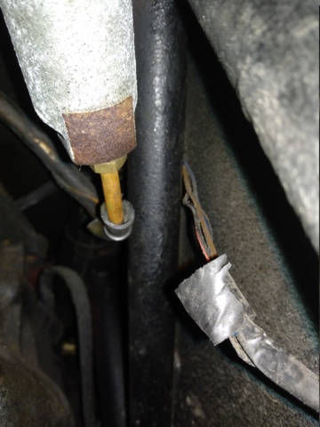
On the nearside, the sensor is well plugged on the car wiring loom. On the off side, nothing plugged. The sensor plug is free. When I replaces the spark plug some weeks ago, I have noticed that offside spark-plugs were lighter than nearside ones (too lean).
My problem is that I don't find any wiring loom to connect the second sensor. Should it come from the nearside, as the first one, ans go further to connect the second sensor ? Or should it come from the other side (offside) alone ? I don't find anything that could look like I'm looking for.
I already have the wiring diagram for 290 S, but for non-cat cars. I don't have any information about lambda sensors and specific wiring looms for it, no more than wiring colours for it.
All the best
It's now time for me to ask your help.
My 1992 S3C has been decatalysed (I don't know when). Catalytic converters were removed with the short exhaust manifolds. Long non-cat manifolds were installed with lambda nut welded on. Genuine lambda sensors are screwed on it. I'm pretty sure that there are the genuine one because they are Bosch brand, with the correct number, and the Ford plastic 3-pin connector.... Black, not white as I have seen here.
https://www.pistonheads.com/gassing/topic.asp?h=0&...
On the nearside, the sensor is well plugged on the car wiring loom. On the off side, nothing plugged. The sensor plug is free. When I replaces the spark plug some weeks ago, I have noticed that offside spark-plugs were lighter than nearside ones (too lean).
My problem is that I don't find any wiring loom to connect the second sensor. Should it come from the nearside, as the first one, ans go further to connect the second sensor ? Or should it come from the other side (offside) alone ? I don't find anything that could look like I'm looking for.
I already have the wiring diagram for 290 S, but for non-cat cars. I don't have any information about lambda sensors and specific wiring looms for it, no more than wiring colours for it.
All the best
Hi Florian. Welcome to the 'S'-community!
My 1990 car is a de-catted S3C (note: under UK regulations the lower CO requirements didn't come in until 1992, so we're OK without the cat, as long as the tester doesn't know that the car ought to have one! I don't suppose you have these problems?)
My installation sounds just like yours (that is, no de-cat pipes). I'd like to see a photo of yours.
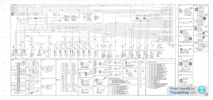
The engine wiring diagram I've found that matches my installation is that for a 1990 German-made Ford Sierra XR4x4.
It's four A4 pages; PM me with your email address and I'll send you the files. I can't get the links to show on here!
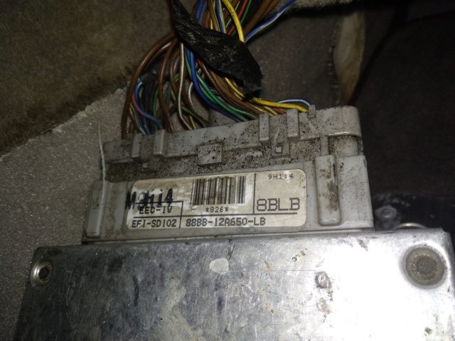
I've found the wiring colour codes match exactly with my car, right back to the ECU terminals. By the way, do you have the 88BB-12A650-LB ECU as I do, and some other S3C owners? This also seems to be correct in the Fordopedia reference list.
Both my sensors were broken: they are heated (three-wire) sensors and the heaters were open-circuit. The Granada/Sierra Bosch type are fine. I rewired my sensors using a seven-core cable soldered and heatshrunk to the sensor wires (the Bosch-type connectors on the car had previously been replaced with some unsafe-looking crimp connectors). I also had to find and replace the heater supply fuse.
Quick check of the heated sensors: turn on the ignition, wait 5 minutes, and the sensors get warm to touch! The car will certainly never be happy if the sensors are not pre-heated.
My car is now running reasonably well and has passed two MoT tests, so I'm moderately confident of the S3C setup.
I'll be happy to help any way I can.
Good luck!
John
My 1990 car is a de-catted S3C (note: under UK regulations the lower CO requirements didn't come in until 1992, so we're OK without the cat, as long as the tester doesn't know that the car ought to have one! I don't suppose you have these problems?)
My installation sounds just like yours (that is, no de-cat pipes). I'd like to see a photo of yours.
The engine wiring diagram I've found that matches my installation is that for a 1990 German-made Ford Sierra XR4x4.
It's four A4 pages; PM me with your email address and I'll send you the files. I can't get the links to show on here!
I've found the wiring colour codes match exactly with my car, right back to the ECU terminals. By the way, do you have the 88BB-12A650-LB ECU as I do, and some other S3C owners? This also seems to be correct in the Fordopedia reference list.
Both my sensors were broken: they are heated (three-wire) sensors and the heaters were open-circuit. The Granada/Sierra Bosch type are fine. I rewired my sensors using a seven-core cable soldered and heatshrunk to the sensor wires (the Bosch-type connectors on the car had previously been replaced with some unsafe-looking crimp connectors). I also had to find and replace the heater supply fuse.
Quick check of the heated sensors: turn on the ignition, wait 5 minutes, and the sensors get warm to touch! The car will certainly never be happy if the sensors are not pre-heated.
My car is now running reasonably well and has passed two MoT tests, so I'm moderately confident of the S3C setup.
I'll be happy to help any way I can.
Good luck!
John
Thank you for your help Phillpot. I doubt my car would have a single sensor system. Why do they buy a brand new Bosh sensor just to plug a hole.... strange. Or the ECU could have been changed by an old Granada model that need only one sensor. I will have a look to the ECU number.
 They don't know what is a S
  Sometime, they have never seen a RHD car
  How do you want they know an S3C has to be catalyzed ?
  That's not written on the V5 french equivalent.
Luckily, I have a picture on my phone to show.... The car is 100 miles from me during the working week.
Don't worry about the swirl pot, it has already been removed, blasted and painted with an epoxy paint. With the battery stand.
As you advice, I will test the warming function of the connected sensor.
In fact the car is running pretty well. 0.58% for the CO ratio few month ago, but I have several symptoms that tell me there is anything wrong. The car is running well when cold, and when warm, but between these two states, the engine tends to stall. The iddle speed is swinging.
Other symptom, when driving, when I put my foot down, the engine tend to struggle before seeding up (too lean). And as I already said, the 3 right-side plugs are lighter than left-side ones.
mentall said:
note: under UK regulations the lower CO requirements didn't come in until 1992, so we're OK without the cat, as long as the tester doesn't know that the car ought to have one! I don't suppose you have these problems?
That's exactly the same rules in France. Catalytic converter is not obligatory before 01/01/1993 except if it was installed before by the manufacturer. But testers in France don't know the TVR brand.... They don't know what is a S Sometime, they have never seen a RHD car How do you want they know an S3C has to be catalyzed ? That's not written on the V5 french equivalent.Luckily, I have a picture on my phone to show.... The car is 100 miles from me during the working week.
Don't worry about the swirl pot, it has already been removed, blasted and painted with an epoxy paint. With the battery stand.
As you advice, I will test the warming function of the connected sensor.
In fact the car is running pretty well. 0.58% for the CO ratio few month ago, but I have several symptoms that tell me there is anything wrong. The car is running well when cold, and when warm, but between these two states, the engine tends to stall. The iddle speed is swinging.
Other symptom, when driving, when I put my foot down, the engine tend to struggle before seeding up (too lean). And as I already said, the 3 right-side plugs are lighter than left-side ones.

Glad you're back, Florian!
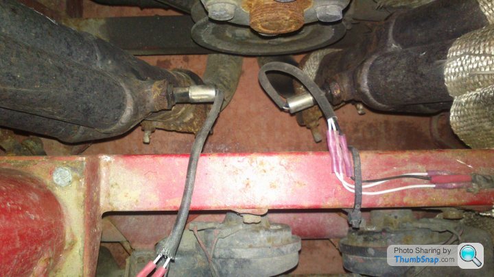
That looks just like mine (before I rewired it).
I too had blacker plugs on the right bank: I put it down to the Lambda wiring being reversed L-R when I bought the car.
But that was the least of my problems. Now they're all a good colour, but it took several ECU learning cycles to get to that stage.
Your running problems could be due to the Lambdas. But it's worth checking the MAP sensor and wiring, and looking for air leaks. My PCV valve on the right rocker cover jumps out for fun, and gives me just those symptoms.
Fefeu52 said:
Could you tel me where you found the heater fuse holder (C-1135) ? Inside the car, near the ECU, or in the engine compartment ?
Near the ECU and the relays: one of several unidentified blade fuse holders, each hanging on the end of its own wires.As always, this may not be original wiring.
mentall said:
Here's the link to the XROC (XR Owners Club) web forum thread where I found the engine wiring diagram. It's the last post in the thread.
It's difficult, but I've blown it up and printed it out so I can just about read it. Good luck to anybody doing the same!
Is this any good???? From Here http://www.veryuseful.com/mustang/tech/engine/It's difficult, but I've blown it up and printed it out so I can just about read it. Good luck to anybody doing the same!

This is a wonderfully clear point-to-point diagram PS.
Probst's book has over a hundred of these, for every US/CDN Ford variant of the era, including V6's.
But none of them has wiring colours anything like ours; nor does this one. Nor do Granadas (presumably made in Genk?) And there's no diagram for the 2.9 engine wiring (with or without Lambdas) in the Haynes Sierra V6 Manual.
The Gnomes of Cologne had their own way of doing things.
So we've struggled on with this diagram.
If anybody has a diagram similar to yours for the Sierra XR4x4 wiring, PLEASE make it available on here!
Penelope Stopit said:
There isn't as much in it as how it first looked to me
Agreed: it's not rocket surgery!First problem is the colour coding, second problem is where the (mostly) power connections on this diagram vanish off the page to (presumably) a set of Sierra body wiring schematics, which we don't have.
So we can't identify the different fused, switched or permanent supplies (and wires) that we are connected to (except the sensors and actuators of course). And I expect TVR approached the problem by 'making it work' in-situ; we don't have an S3C/S4C diagram to help us.
As an example: on my car there was NO WIRE in the harness going to ECU pin 1: Keep-Alive-Memory supply. Hence, no diagnostic outputs, and presumably not much adaptive control memory. I provided a (fused) feed from the radio supply, and now have diagnostics that do make sense.
So I would need to survey the whole system on the car, and link it to Steve Heath's V6, non-cat schematic. That means removing the dashboard (not for the faint-hearted) and cutting all the strapping off the wiring!
One day I'll do this, but probably as the first stage to building and fitting a new, lightweight, technically correct and tidy harness. I've already found lots of advice here from you especially, and others too. Many thanks!
mentall said:
Agreed: it's not rocket surgery!
First problem is the colour coding, second problem is where the (mostly) power connections on this diagram vanish off the page to (presumably) a set of Sierra body wiring schematics, which we don't have.
So we can't identify the different fused, switched or permanent supplies (and wires) that we are connected to (except the sensors and actuators of course). And I expect TVR approached the problem by 'making it work' in-situ; we don't have an S3C/S4C diagram to help us.
As an example: on my car there was NO WIRE in the harness going to ECU pin 1: Keep-Alive-Memory supply. Hence, no diagnostic outputs, and presumably not much adaptive control memory. I provided a (fused) feed from the radio supply, and now have diagnostics that do make sense.
So I would need to survey the whole system on the car, and link it to Steve Heath's V6, non-cat schematic. That means removing the dashboard (not for the faint-hearted) and cutting all the strapping off the wiring!
One day I'll do this, but probably as the first stage to building and fitting a new, lightweight, technically correct and tidy harness. I've already found lots of advice here from you especially, and others too. Many thanks!
I now fully understand what you need to achieve from what you haveFirst problem is the colour coding, second problem is where the (mostly) power connections on this diagram vanish off the page to (presumably) a set of Sierra body wiring schematics, which we don't have.
So we can't identify the different fused, switched or permanent supplies (and wires) that we are connected to (except the sensors and actuators of course). And I expect TVR approached the problem by 'making it work' in-situ; we don't have an S3C/S4C diagram to help us.
As an example: on my car there was NO WIRE in the harness going to ECU pin 1: Keep-Alive-Memory supply. Hence, no diagnostic outputs, and presumably not much adaptive control memory. I provided a (fused) feed from the radio supply, and now have diagnostics that do make sense.
So I would need to survey the whole system on the car, and link it to Steve Heath's V6, non-cat schematic. That means removing the dashboard (not for the faint-hearted) and cutting all the strapping off the wiring!
One day I'll do this, but probably as the first stage to building and fitting a new, lightweight, technically correct and tidy harness. I've already found lots of advice here from you especially, and others too. Many thanks!
There is much more work needed to draw a correct diagram than what the job looks like...."Better hey"
Yes that would be a great time to carry out a full wiring harness strip down and all would then be revealed
The thing is you would very likely be doing it for others and not yourself due to you wishing to carry out alterations when making a new loom
Enjoy rewiring your car when the time comes, please post plenty of pictures as you work through it and if I am posting to this forum at that time please feel free to ask about anything
I love vehicle electrics.......
mentall said:
As an example: on my car there was NO WIRE in the harness going to ECU pin 1: Keep-Alive-Memory supply. Hence, no diagnostic outputs, and presumably not much adaptive control memory. I provided a (fused) feed from the radio supply, and now have diagnostics that do make sense
Thanks for the information, I'll also check that  I want to build a default code reader :
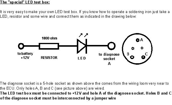
Picture from here : https://passionford.com/forum/ford-sierra-sapphire...
And codes are there :
Hi,
A little report of my afternoon work.
On the connector, I founded the Blue/white on the #43 pin and Blue/Black on #29. The #29 is really easy to remove from the connector and the isolation is broken. So somebody tried to find a problem previously near there.
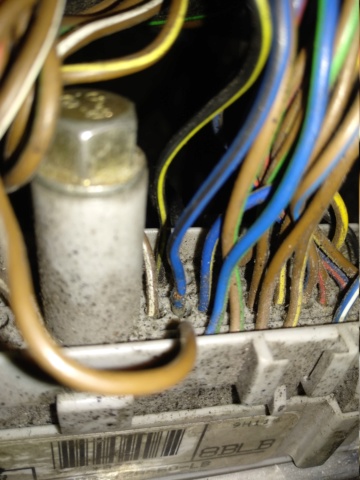
I found the fuse : with 2 black/red wires to power 2 sensors. The fuse is OK.
I tested the 2 warming resistances and both seems to be OK (3,6 ohm.... 40W seems correct)
Now I have to play to a new game : "Folow the wire"
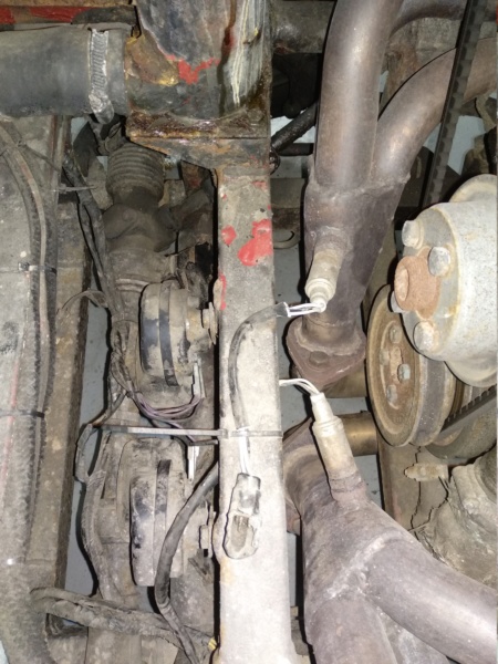
The blue/black wire goes out from the passenger compartment with the main loom, nearside. In the engine bay, the loom divides in 2 parts. The first one go to the bottom to go in front of the engine (lighting and horn for example). The other part stays on top to go to the other side of the engine, going behind the engine, on top of the bell housing. Near the loom separation, the left-side lambda loom comes out from the main loom. Here I can find the blue/black wire for the right sensor.
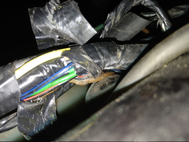
The blue/black wire was going trough the behind-engine loom, then going back :eek, then going on :eek, and then going out to pass along the gearbox : And always with 2 other wires ..... Black/red and Brown 
You can see the clutch sleeve.
So I found what I was looking for but I don't understand what it is doing here. I didn't succeed to pull on it. I think the plug is always on and a plastic collar retains it. I will remove the central console to access from the gear lever hole.
to be continued....
A little report of my afternoon work.
mentall said:
By the way, do you have the 88BB-12A650-LB ECU as I do, and some other S3C owners? This also seems to be correct in the Fordopedia reference list.
Yes, that's it :On the connector, I founded the Blue/white on the #43 pin and Blue/Black on #29. The #29 is really easy to remove from the connector and the isolation is broken. So somebody tried to find a problem previously near there.
I found the fuse : with 2 black/red wires to power 2 sensors. The fuse is OK.
I tested the 2 warming resistances and both seems to be OK (3,6 ohm.... 40W seems correct)
Now I have to play to a new game : "Folow the wire"
The blue/black wire goes out from the passenger compartment with the main loom, nearside. In the engine bay, the loom divides in 2 parts. The first one go to the bottom to go in front of the engine (lighting and horn for example). The other part stays on top to go to the other side of the engine, going behind the engine, on top of the bell housing. Near the loom separation, the left-side lambda loom comes out from the main loom. Here I can find the blue/black wire for the right sensor.
The blue/black wire was going trough the behind-engine loom, then going back :eek, then going on :eek, and then going out to pass along the gearbox :
And always with 2 other wires ..... Black/red and Brown You can see the clutch sleeve.
So I found what I was looking for but I don't understand what it is doing here. I didn't succeed to pull on it. I think the plug is always on and a plastic collar retains it. I will remove the central console to access from the gear lever hole.
to be continued....
Gassing Station | S Series | Top of Page | What's New | My Stuff