Injector wiring loom
Discussion


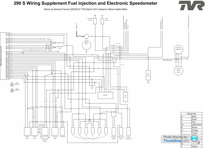
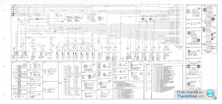
I can't zoom this German Ford diagram sufficiently to be able to tell for sure, but I suspect it's the one I posted on here a while ago. If so, then it is specifically the diagram for the Sierra XR4x4 engine (as used in the S3C/S4C) which has a catalyser, and different ECU and sensor components than the OP's non-cat car. It has no AFM's and has a manifold pressure (MAP) sensor. It also has a different injector harness, with different colour-coding and connectors.
That's not to say the harness can't be adapted for a non-cat car, and indeed that may be what has happened in the OP's car, explaining the differences in coding and connectors.
That's not to say the harness can't be adapted for a non-cat car, and indeed that may be what has happened in the OP's car, explaining the differences in coding and connectors.
mentall said:
I can't zoom this German Ford diagram sufficiently to be able to tell for sure, but I suspect it's the one I posted on here a while ago. If so, then it is specifically the diagram for the Sierra XR4x4 engine (as used in the S3C/S4C) which has a catalyser, and different ECU and sensor components than the OP's non-cat car. It has no AFM's and has a manifold pressure (MAP) sensor. It also has a different injector harness, with different colour-coding and connectors.
That's not to say the harness can't be adapted for a non-cat car, and indeed that may be what has happened in the OP's car, explaining the differences in coding and connectors.
Yes am pretty sure the Ford diagram came in 4 parts from a topic or link that you posted up and I roughly joined it or did you, can't remember That's not to say the harness can't be adapted for a non-cat car, and indeed that may be what has happened in the OP's car, explaining the differences in coding and connectors.
Can be seen on the previous page that the loom now about to be wired in is a match to the loom in RayTVRs car
The Ford injector loom pin-outs also match up with the TVR pin-outs (diagram shown in previous page)
As RayTVR pointed out on the previous page, the loom going in is an injector loom
Everything cross checks as good to go
Don't take this the wrong way, I do stand to be corrected and do make mistakes like we all do
The thing is, been over this several times and found only one snag which will be posted for MisterTee shortly
Please do take a look at below post and post your opinion back here, perhaps RayTVR will also comment or anyone else for that matter.....The more the merrier
Edited by Penelope Stopit on Friday 21st February 15:43
MisterTee and anyone else that will kindly take a look and give an opinion
There seems to be an error in the TVR diagram and I really should have spotted it yet have never needed to check through an idle valve circuit, hence my ignorance remained until very recently looking through several Ford idle valve circuits
In the below TVR diagram, the idle valve is shown as having one of its cables Brown/yellow -------Connects to ECU Pin 21
and this matches several other EECIV diagrams and looks correct
The error (what seems to be an error) involves the other idle valve cable, in the below TVR diagram the idle valves other cable is shown connected to the negative injector signal of one bank of injectors, yet all Ford EECIV diagrams show the other idle valve cable connected to the positive that supplies both banks of injectors (This makes sense to me)
TVR Diagram

Ford Diagram

If whoever made the new loom was following the TVR diagram it would account for there being a problem with the new loom
This following information from a document found online does back-up what I suspect to be wrong with the TVR diagram......
The Intake Air Bypass (IAB) is a solenoid (also known as an Idle Air Controller IAC) – operated air control valve used on Ford SEFI engines. The EEC controls the valve by switching its ground wire on and off at a frequency of about 60 hertz (cycles per second). That rate is high enough that the valve never closes and instead “dithers” somewhere between open and closed. The more duty cycle used the more open the valve becomes and vise-versa. If the throttle stop is set correctly, the engine will not idle if the IAB has failed closed.
The IAB contains a diode, so if you are checking the solenoid with an ohmmeter for resistance, you should get 7-13 ohms from VPWR(+ lead) to ISC(- lead) and infinite ohms when checking ISC(+ lead) to VPWR(- lead) due to the diode. With the IAB disconnected, check resistance of each lead to the IAB case for shorts – resistance should be high and any reading of 0-13 ohms indicates a short to the case – replace the IAB.
In the car with the ignition on, you should have 12v to both wires until the EEC starts to “dither” and then the voltage will come down. If it does not, then the solenoid winding may be open and be an indication of a bad IAB.
You can use an old dwell meter if you don’t have a multi-meter with a frequency measuring capability to check the IAB. Use straight pins through the wire jackets to make the connection to the dwell meter and set on the 4-cylinder setting. Run the engine at idle and if the dwell meter reads “0” or “90”, the EEC is not functioning correctly and needs to be replaced to restore proper idle control. Of course if you have a frequency reading multi-meter, use it to check for the EEC control of the IAB.
If the IAB is good and idle is too high, someone may have messed with the idle stop screw on the TB when they had problems in the past. Try this procedure:
1. Disconnect battery & turn on headlights for 5 minutes to erase KAM memory.
2. With the engine off, install a .025” feeler gauge between the idle stop-screw and throttle lever and adjust for that .025” gap.
3. Run the engine for about 30 seconds at 2500 rpm.
4. Return to idle and set the idle stop-screw for 650-700 rpm.
5. Turn the car off, restart and let idle for 2 minutes.
6. If idle is within specification you’re done except that you should pull the IAB connector to see if the engine dies. It should.
There seems to be an error in the TVR diagram and I really should have spotted it yet have never needed to check through an idle valve circuit, hence my ignorance remained until very recently looking through several Ford idle valve circuits
In the below TVR diagram, the idle valve is shown as having one of its cables Brown/yellow -------Connects to ECU Pin 21
and this matches several other EECIV diagrams and looks correct
The error (what seems to be an error) involves the other idle valve cable, in the below TVR diagram the idle valves other cable is shown connected to the negative injector signal of one bank of injectors, yet all Ford EECIV diagrams show the other idle valve cable connected to the positive that supplies both banks of injectors (This makes sense to me)
TVR Diagram
Ford Diagram
If whoever made the new loom was following the TVR diagram it would account for there being a problem with the new loom
This following information from a document found online does back-up what I suspect to be wrong with the TVR diagram......
The Intake Air Bypass (IAB) is a solenoid (also known as an Idle Air Controller IAC) – operated air control valve used on Ford SEFI engines. The EEC controls the valve by switching its ground wire on and off at a frequency of about 60 hertz (cycles per second). That rate is high enough that the valve never closes and instead “dithers” somewhere between open and closed. The more duty cycle used the more open the valve becomes and vise-versa. If the throttle stop is set correctly, the engine will not idle if the IAB has failed closed.
The IAB contains a diode, so if you are checking the solenoid with an ohmmeter for resistance, you should get 7-13 ohms from VPWR(+ lead) to ISC(- lead) and infinite ohms when checking ISC(+ lead) to VPWR(- lead) due to the diode. With the IAB disconnected, check resistance of each lead to the IAB case for shorts – resistance should be high and any reading of 0-13 ohms indicates a short to the case – replace the IAB.
In the car with the ignition on, you should have 12v to both wires until the EEC starts to “dither” and then the voltage will come down. If it does not, then the solenoid winding may be open and be an indication of a bad IAB.
You can use an old dwell meter if you don’t have a multi-meter with a frequency measuring capability to check the IAB. Use straight pins through the wire jackets to make the connection to the dwell meter and set on the 4-cylinder setting. Run the engine at idle and if the dwell meter reads “0” or “90”, the EEC is not functioning correctly and needs to be replaced to restore proper idle control. Of course if you have a frequency reading multi-meter, use it to check for the EEC control of the IAB.
If the IAB is good and idle is too high, someone may have messed with the idle stop screw on the TB when they had problems in the past. Try this procedure:
1. Disconnect battery & turn on headlights for 5 minutes to erase KAM memory.
2. With the engine off, install a .025” feeler gauge between the idle stop-screw and throttle lever and adjust for that .025” gap.
3. Run the engine for about 30 seconds at 2500 rpm.
4. Return to idle and set the idle stop-screw for 650-700 rpm.
5. Turn the car off, restart and let idle for 2 minutes.
6. If idle is within specification you’re done except that you should pull the IAB connector to see if the engine dies. It should.


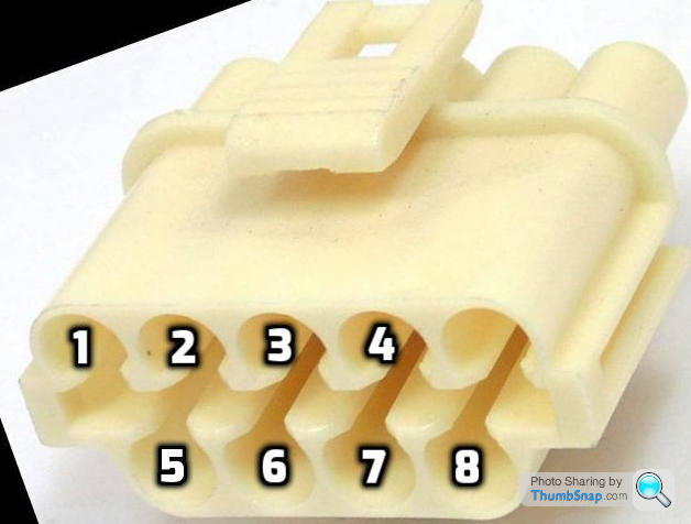
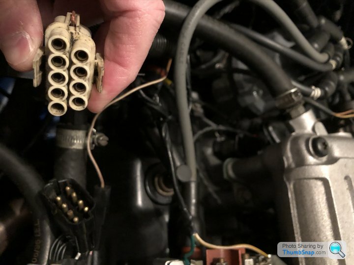
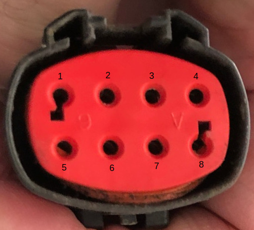
Okay, so on the car side (main loom that connects to the ECU), reading the plugs from top row, left to right as 1-4 and the lower row from left to right as 5-8, the wires are as follows:-
1 brown yellow
2 black
3 brown
4 brown
5 brown black
6 brown green
7 brown
8 brown green
Which pretty much match RayTVRs colours, albeit in a different order (but I might be holding the plug upside down).
MisterTee said:
Okay, so on the car side (main loom that connects to the ECU), reading the plugs from top row, left to right as 1-4 and the lower row from left to right as 5-8, the wires are as follows:-
1 brown yellow
2 black
3 brown
4 brown
5 brown black
6 brown green
7 brown
8 brown green
Which pretty much match RayTVRs colours, albeit in a different order (but I might be holding the plug upside down).
Unfortunately there is no easy way to work out what cable goes where, having a vehicle with the same plug wouldn't help
Have posted all the information needed at the bottom of the previous page and have nothing more to add apart from
It would have been nice of you to comment about the error found in the TVR diagram and if that diagram was used to make the new loom that you suspect to be the problem
But whatever, I won't lose any sleep over it
Good luck in completing the termination of the plug/socket
Suggest that you first check the pin-outs of the 2 brown cables that are side by side as they are very likely terminating at ECU pins 58 and 59 for running the injectors, once you've sorted 2 x browns for injectors you will be left with
3rd Brown -----------------------Connects to ECU Pin 46
Once browns are sorted you will only need to check the pin-outs of the 2 Brown/green cables
As mentioned above, all information needed is at the bottom of the previous page
If you were to turn that plug over through 180 degrees, the colours will match up with RayTVRs list on the previous page
The thing is you would be taking a big chance in terminating them from that order and could easily damage the ECU
Edited by Penelope Stopit on Saturday 22 February 15:19
Many thanks for all of your help, Penelope, it is very much appreciated.
Sorry I haven’t had much time to respond to everything you have posted, I certainly do not mean to offend anyone who is trying to help me get this sorted. What you write about the error in the wiring diagram makes perfect sense and could definitely be the root cause of my woes.
I just need some good weather and some quality time to read and digest what you and others have posted and then be brave enough to give it all a go!
Thanks again.
Andy
MisterTee said:
Many thanks for all of your help, Penelope, it is very much appreciated.
Sorry I haven’t had much time to respond to everything you have posted, I certainly do not mean to offend anyone who is trying to help me get this sorted. What you write about the error in the wiring diagram makes perfect sense and could definitely be the root cause of my woes.
I just need some good weather and some quality time to read and digest what you and others have posted and then be brave enough to give it all a go!
Thanks again.
Andy
No problem whatsoever ( "whatsoever" apparently an intense form of whatever. Learn something every day)Sorry I haven’t had much time to respond to everything you have posted, I certainly do not mean to offend anyone who is trying to help me get this sorted. What you write about the error in the wiring diagram makes perfect sense and could definitely be the root cause of my woes.
I just need some good weather and some quality time to read and digest what you and others have posted and then be brave enough to give it all a go!
Thanks again.
Andy
Thank you for commenting about the error in the TVR diagram possibly being the cause, if this is the case.....Many here including myself feel your pain more than ever
Horrible, nothing but horrible
Was offered lots of money a while back to verify automotive diagrams, perhaps you can understand why I said "No Way".......A few diagrams are enough
Will keep an eye out for your progress on this and possibly attempt to post something that will help simplify the testing before terminating
Just a quick update!
Managed to spend some time on the car today and ........... success!
I now have a car that starts on the choke, runs perfectly at tick over, revs and runs on all 6 cylinders.
A very happy and relieved man!
Just need to get it tested, taxed and driven.
Thanks to everyone who has offered their help and advice - much appreciated.
Andy
MisterTee said:
Just a quick update!
Managed to spend some time on the car today and ........... success!
I now have a car that starts on the choke, runs perfectly at tick over, revs and runs on all 6 cylinders.
A very happy and relieved man!
Just need to get it tested, taxed and driven.
Thanks to everyone who has offered their help and advice - much appreciated.
Andy
Lovely, all's well that ends well, it's been a pleasure working through the circuit for you and finding possible reasons as to why the problem came aboutManaged to spend some time on the car today and ........... success!
I now have a car that starts on the choke, runs perfectly at tick over, revs and runs on all 6 cylinders.
A very happy and relieved man!
Just need to get it tested, taxed and driven.
Thanks to everyone who has offered their help and advice - much appreciated.
Andy
This particular problem is the best one ever posted here and I admire you for sticking at it as there was no simple fix
Out of curiosity
How did you end up checking the wiring so as to be sure the plug termination was correct?
If you should answer "took a chance", back some horses at Cheltenham next week
Thanks Penelope
Let’s just say I’ve put a lottery ticket on for tonight! And, I might just start checking the horses at Cheltenham.
Unfortunately my knowledge and skills are nowhere near anything like yours, so very much relied on Lady Luck, in addition to following the advice on here (of course).
Andy
Let’s just say I’ve put a lottery ticket on for tonight! And, I might just start checking the horses at Cheltenham.
Unfortunately my knowledge and skills are nowhere near anything like yours, so very much relied on Lady Luck, in addition to following the advice on here (of course).
Andy
Edited by MisterTee on Saturday 7th March 18:55
MisterTee said:
Thanks Penelope
Let’s just say I’ve put a lottery ticket on for tonight! And, I might just start checking the horses at Cheltenham.
Unfortunately my knowledge and skills are nowhere near anything like yours, so very much relied on Lady Luck, in addition to following the advice on here (of course).
Andy
Ok then, nicely fixed, enjoy, appreciate you posting backLet’s just say I’ve put a lottery ticket on for tonight! And, I might just start checking the horses at Cheltenham.
Unfortunately my knowledge and skills are nowhere near anything like yours, so very much relied on Lady Luck, in addition to following the advice on here (of course).
Andy
lewdon said:
Can you please let us know what the problem turned out to be, and how you cured it? Someone else may have a similar problem one day.
MisterTee said:
I’ve just had the engine and gearbox rebuilt and whilst the car was in bits, I had a new injector loom made. Since the rebuild the cold start has stopped working
MisterTee said:
Without the engine running, the star tester shows two error codes - 16 and 12 :-
16 - Electronic ignition - IDM circuit fault
12 - Idle Speed Control motor or Air Bypass not controlling idle properly
16 - Electronic ignition - IDM circuit fault
12 - Idle Speed Control motor or Air Bypass not controlling idle properly
MisterTee said:
Been and had a poke about this morning and the full near side bank of cylinders are not firing at all. Whipped the plugs out and gave them a clean, but no different.
MisterTee said:
Thinking about it, none of the plugs were wet when I took them out
Penelope Stopit said:
Ignoring 16 - Electronic ignition - IDM circuit fault for the time being
Have a hunch what's happening, wish the car was here to prove it
Looking at the below diagram found here in these forums some time in the past
The idle speed control connects to one bank of injectors signal cable
There is a diode in parallel with the idle speed control that will very likely be in the loom
One bank of injectors will cease to operate if the idle speed control is going short or semi short circuit, its wiring going short circuit or the above mentioned diode is short circuit or wired the wrong way around
Hoping that the above helps find and solves the problem, should the problem not be due to any of the above mentioned, a short circuit on the same injector banks signal cable will cause the injectors and idle speed control to fail
Due to the loom being new, DIODE problem is setting off the alarm in my head
MisterTee said:
I’m just needing a couple of new connectors then I should be able to test out another loom to see if it cures my problems. Penelope has convinced me it is a loom/diode related issue, which based on all that I have read I tend to agree with.
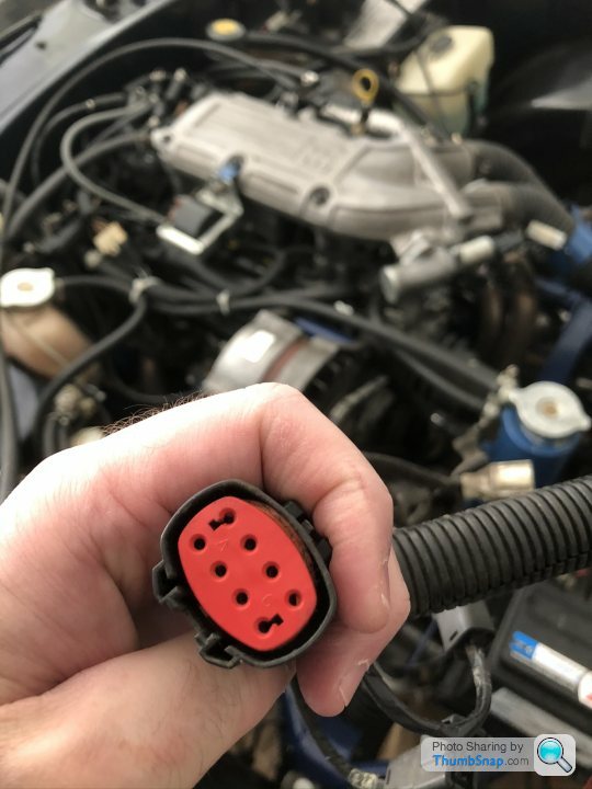
RayTVR kindly loaned me a spare loom, but the main connector was different to mine on the car. I’ve managed to get another loom to call my own now and just need to get that fitted
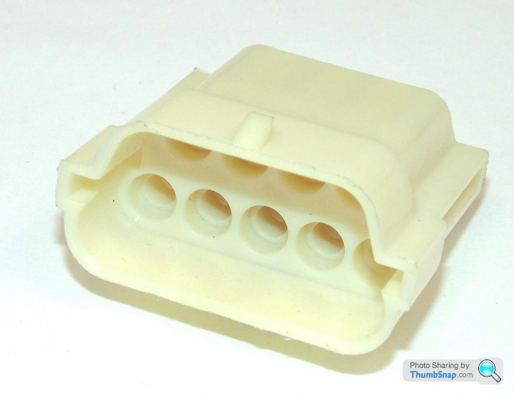
Anyone any ideas where I can get the ‘male’ connector to fit this? I’ve scoured various websites but can’t seem to find anything that looks remotely like it.
RayTVR kindly loaned me a spare loom, but the main connector was different to mine on the car. I’ve managed to get another loom to call my own now and just need to get that fitted
Anyone any ideas where I can get the ‘male’ connector to fit this? I’ve scoured various websites but can’t seem to find anything that looks remotely like it.
Penelope Stopit said:
Been all over the internet this morning looking for a male 8 way plug to match up, no joy
Have links to housings that match the TVR housing, terminals plus lock strip can also be ordered, they're all shown on these pages
https://www.automotiveconnectors.com/9-way-lucas-r...
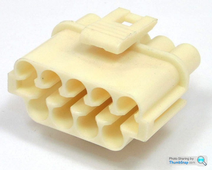
https://www.automotiveconnectors.com/9-way-lucas-r...
Have links to housings that match the TVR housing, terminals plus lock strip can also be ordered, they're all shown on these pages
https://www.automotiveconnectors.com/9-way-lucas-r...
https://www.automotiveconnectors.com/9-way-lucas-r...
MisterTee said:
Many thanks Penelope - that is more helpful, actually.
I had been looking for this type of connector, as this is exactly the type fitted to the main loom. I was led to believe that it wasn’t a proper Ford or TVR fit connector which is what made me start my search for a male connector for the above. Below is a picture of the connector on my main ECU loom, which looks to be the same as the ones you have found.
Andy
Penelope Stopit said:
Using the following information found in these forums and the above information provided by RayTVR and yourself

As long as your car side plug cables colours match with RayTVRs car side plug cables colours
With the ECU Disconnected
You will need to check from the car side plug cables terminals to the ECU plug terminals with a multimeter, you need to be sure that all duplicate cables colours destinations are known and then labelled, obviously label the engine side plugs cables 1 to 8
There shouldn't be any need to check the following but it won't do any harm to do so
Pins 1, 5 and 6 cables aren't duplicated at the car side plug
As can be seen, 3 x Browns and 2 x Brown/greens are the problem
Below is a list that will assist you in checking car side plug to ECU terminations, haven't included every circuit the cables connect to as that will only complicate things
Included the pin numbers that the car side cables would connect to at the engine side plug, even though you'll be changing the engine side plug
Best that you match the engine side cables terminals orientation to the TVR side plug, if you were to alter the orientation of the terminals in the TVR side plug their could be a big problem in the future if someone fitted a TVR injector loom and plugged it into an altered plug
If you're not sure of anything.....ask, here's the list for car side testing and labelling
Pin 1 - Cable Number 31B-20 Colour BR-SW = Brown/black --------Connects to ECU Pin 26
Pin 2 - Cable Number 31B-13 Colour BR-GN = Brown/green -------Connects to ECU Pin 47
Pin 3 - Cable Number 31-75 Colour BR = Brown -----------------------Connects to ECU Pin 46
Pin 4 - Cable Number 31B-75 Colour BR-GN = Brown/green -------Connects to ECU Pin 7
Pin 5 - Cable Number 31B-73 Colour BR-GE = Brown/yellow -------Connects to ECU Pin 21
Pin 6 - Cable Number 15-6 Colour SW = Black -------------------------Connects to ECU Pins 37 and 57 and Main Engine/ECU Relay Terminal 87
Pin 7 - Cable Number 31-73 Colour BR = Brown -----------------------Connects to ECU Pin 58
Pin 8 - Cable Number 31-74 Colour BR = Brown -----------------------Connects to ECU Pin 59
As long as your car side plug cables colours match with RayTVRs car side plug cables colours
With the ECU Disconnected
You will need to check from the car side plug cables terminals to the ECU plug terminals with a multimeter, you need to be sure that all duplicate cables colours destinations are known and then labelled, obviously label the engine side plugs cables 1 to 8
There shouldn't be any need to check the following but it won't do any harm to do so
Pins 1, 5 and 6 cables aren't duplicated at the car side plug
| Brown/black | 1. | Brown black white dashes |
| Brown/green???? | 2. | Brown green |
| Brown???? | 3. | Brown |
| Brown/green???? | 4. | Brown green white dashes |
| Brown yellow | 5, | Brown yellow |
| Black | 6. | Black |
| Brown???? | 7. | Brown Black |
| Brown???? | 8. | Brown |
As can be seen, 3 x Browns and 2 x Brown/greens are the problem
Below is a list that will assist you in checking car side plug to ECU terminations, haven't included every circuit the cables connect to as that will only complicate things
Included the pin numbers that the car side cables would connect to at the engine side plug, even though you'll be changing the engine side plug
Best that you match the engine side cables terminals orientation to the TVR side plug, if you were to alter the orientation of the terminals in the TVR side plug their could be a big problem in the future if someone fitted a TVR injector loom and plugged it into an altered plug
If you're not sure of anything.....ask, here's the list for car side testing and labelling
Pin 1 - Cable Number 31B-20 Colour BR-SW = Brown/black --------Connects to ECU Pin 26
Pin 2 - Cable Number 31B-13 Colour BR-GN = Brown/green -------Connects to ECU Pin 47
Pin 3 - Cable Number 31-75 Colour BR = Brown -----------------------Connects to ECU Pin 46
Pin 4 - Cable Number 31B-75 Colour BR-GN = Brown/green -------Connects to ECU Pin 7
Pin 5 - Cable Number 31B-73 Colour BR-GE = Brown/yellow -------Connects to ECU Pin 21
Pin 6 - Cable Number 15-6 Colour SW = Black -------------------------Connects to ECU Pins 37 and 57 and Main Engine/ECU Relay Terminal 87
Pin 7 - Cable Number 31-73 Colour BR = Brown -----------------------Connects to ECU Pin 58
Pin 8 - Cable Number 31-74 Colour BR = Brown -----------------------Connects to ECU Pin 59
Penelope Stopit said:
MisterTee and anyone else that will kindly take a look and give an opinion
There seems to be an error in the TVR diagram and I really should have spotted it yet have never needed to check through an idle valve circuit, hence my ignorance remained until very recently looking through several Ford idle valve circuits
In the below TVR diagram, the idle valve is shown as having one of its cables Brown/yellow -------Connects to ECU Pin 21
and this matches several other EECIV diagrams and looks correct
The error (what seems to be an error) involves the other idle valve cable, in the below TVR diagram the idle valves other cable is shown connected to the negative injector signal of one bank of injectors, yet all Ford EECIV diagrams show the other idle valve cable connected to the positive that supplies both banks of injectors (This makes sense to me)
TVR Diagram
Ford Diagram
If whoever made the new loom was following the TVR diagram it would account for there being a problem with the new loom
This following information from a document found online does back-up what I suspect to be wrong with the TVR diagram......
The Intake Air Bypass (IAB) is a solenoid (also known as an Idle Air Controller IAC) – operated air control valve used on Ford SEFI engines. The EEC controls the valve by switching its ground wire on and off at a frequency of about 60 hertz (cycles per second). That rate is high enough that the valve never closes and instead “dithers” somewhere between open and closed. The more duty cycle used the more open the valve becomes and vise-versa. If the throttle stop is set correctly, the engine will not idle if the IAB has failed closed.
The IAB contains a diode, so if you are checking the solenoid with an ohmmeter for resistance, you should get 7-13 ohms from VPWR(+ lead) to ISC(- lead) and infinite ohms when checking ISC(+ lead) to VPWR(- lead) due to the diode. With the IAB disconnected, check resistance of each lead to the IAB case for shorts – resistance should be high and any reading of 0-13 ohms indicates a short to the case – replace the IAB.
In the car with the ignition on, you should have 12v to both wires until the EEC starts to “dither” and then the voltage will come down. If it does not, then the solenoid winding may be open and be an indication of a bad IAB.
You can use an old dwell meter if you don’t have a multi-meter with a frequency measuring capability to check the IAB. Use straight pins through the wire jackets to make the connection to the dwell meter and set on the 4-cylinder setting. Run the engine at idle and if the dwell meter reads “0” or “90”, the EEC is not functioning correctly and needs to be replaced to restore proper idle control. Of course if you have a frequency reading multi-meter, use it to check for the EEC control of the IAB.
If the IAB is good and idle is too high, someone may have messed with the idle stop screw on the TB when they had problems in the past. Try this procedure:
1. Disconnect battery & turn on headlights for 5 minutes to erase KAM memory.
2. With the engine off, install a .025” feeler gauge between the idle stop-screw and throttle lever and adjust for that .025” gap.
3. Run the engine for about 30 seconds at 2500 rpm.
4. Return to idle and set the idle stop-screw for 650-700 rpm.
5. Turn the car off, restart and let idle for 2 minutes.
6. If idle is within specification you’re done except that you should pull the IAB connector to see if the engine dies. It should.
The newly made loom was the problemThere seems to be an error in the TVR diagram and I really should have spotted it yet have never needed to check through an idle valve circuit, hence my ignorance remained until very recently looking through several Ford idle valve circuits
In the below TVR diagram, the idle valve is shown as having one of its cables Brown/yellow -------Connects to ECU Pin 21
and this matches several other EECIV diagrams and looks correct
The error (what seems to be an error) involves the other idle valve cable, in the below TVR diagram the idle valves other cable is shown connected to the negative injector signal of one bank of injectors, yet all Ford EECIV diagrams show the other idle valve cable connected to the positive that supplies both banks of injectors (This makes sense to me)
TVR Diagram
Ford Diagram
If whoever made the new loom was following the TVR diagram it would account for there being a problem with the new loom
This following information from a document found online does back-up what I suspect to be wrong with the TVR diagram......
The Intake Air Bypass (IAB) is a solenoid (also known as an Idle Air Controller IAC) – operated air control valve used on Ford SEFI engines. The EEC controls the valve by switching its ground wire on and off at a frequency of about 60 hertz (cycles per second). That rate is high enough that the valve never closes and instead “dithers” somewhere between open and closed. The more duty cycle used the more open the valve becomes and vise-versa. If the throttle stop is set correctly, the engine will not idle if the IAB has failed closed.
The IAB contains a diode, so if you are checking the solenoid with an ohmmeter for resistance, you should get 7-13 ohms from VPWR(+ lead) to ISC(- lead) and infinite ohms when checking ISC(+ lead) to VPWR(- lead) due to the diode. With the IAB disconnected, check resistance of each lead to the IAB case for shorts – resistance should be high and any reading of 0-13 ohms indicates a short to the case – replace the IAB.
In the car with the ignition on, you should have 12v to both wires until the EEC starts to “dither” and then the voltage will come down. If it does not, then the solenoid winding may be open and be an indication of a bad IAB.
You can use an old dwell meter if you don’t have a multi-meter with a frequency measuring capability to check the IAB. Use straight pins through the wire jackets to make the connection to the dwell meter and set on the 4-cylinder setting. Run the engine at idle and if the dwell meter reads “0” or “90”, the EEC is not functioning correctly and needs to be replaced to restore proper idle control. Of course if you have a frequency reading multi-meter, use it to check for the EEC control of the IAB.
If the IAB is good and idle is too high, someone may have messed with the idle stop screw on the TB when they had problems in the past. Try this procedure:
1. Disconnect battery & turn on headlights for 5 minutes to erase KAM memory.
2. With the engine off, install a .025” feeler gauge between the idle stop-screw and throttle lever and adjust for that .025” gap.
3. Run the engine for about 30 seconds at 2500 rpm.
4. Return to idle and set the idle stop-screw for 650-700 rpm.
5. Turn the car off, restart and let idle for 2 minutes.
6. If idle is within specification you’re done except that you should pull the IAB connector to see if the engine dies. It should.
Don't work to diagrams before checking they are correct
Edited by Penelope Stopit on Sunday 8th March 09:31
Gassing Station | S Series | Top of Page | What's New | My Stuff