450 SEAC - the return
Discussion


Hi, following the purchase of F719 DCW and the collection on Friday I thought it best to start a new thread and occasionally post updates. There's a few out there not on Facebook and as I've found over the last few days the Pistonheads forums are searchable so my thread may be of use to a SEAC owner in the future.
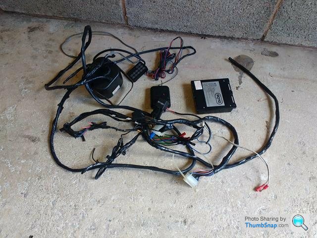
Well second day spend on the car today. Armed with the correct wiring diagram off the 450SE I made short work of returning the ignition wiring back to original. At the same time I replaced the wire feeding the starter solenoid and I now have a car that starts using the ignition key. I then spent the next few hours carefully removing the faulty alarm and associated wiring.
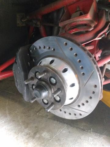
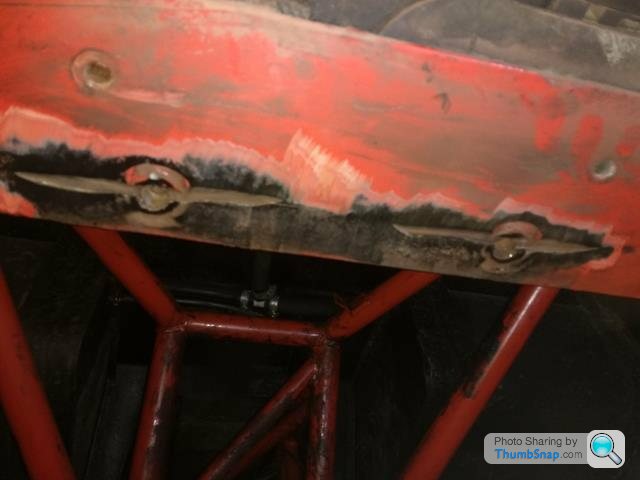
While I was in the wheel arch playing with the solenoid wire I had 10 minutes with the wire brush and the discs came up like new. I will remove, check and clean the pads but the Wilwood 4 pot calipers still look tidy and do not seem to be binding at all. The underside of the car still looks very good, despite it's years in storage.

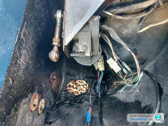
Next job was to tidy up all the original wiring under the steering column and also by the relay/fuse board. As with all the Wedges I've had the drop down flap is distorted and will need some work in the future. Some of the carpet sections were very damp, no doubt from the monsoon trip home on Friday so I've removed them to clean and dry them out.

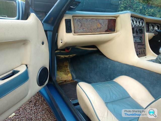
I also had a further play with the leather cleaner. The section under the cubby hole was black with mould but the cleaner seems to be lifting it off without leaving any staining. Considerable further work is needed.
Last job of the afternoon was to look at the non-functioning near side headlamp. The only way in was via a very small hole in the bottom of the wing. There was no way my fat hands would get in there so some very careful enlarging with the jig saw and I could then access the manual winder to get the headlamp up, remove the lens and see what's happening. The rose jointed arm is virtually seized and the motor won't run. If however I wind it manually and then put the power on, the motor does run and immediately re-parks itself in the down position. I'm hoping the limit switches just need a clean. A job for another day. Similarly the inside of the pop up headlamp needs some work. The original ply has de-laminated leaving precious little to attach the lens back to. I'll re-glass it before I reassemble.

Overall very pleased with the progress. The engine now starts with the key, runs great and sounds amazing, the original wheel centres were found under the passenger seat, the wiring is now all sorted and I think the interior trim (except the veneers) looks like it will clean up nicely. Cheers.
Well second day spend on the car today. Armed with the correct wiring diagram off the 450SE I made short work of returning the ignition wiring back to original. At the same time I replaced the wire feeding the starter solenoid and I now have a car that starts using the ignition key. I then spent the next few hours carefully removing the faulty alarm and associated wiring.
While I was in the wheel arch playing with the solenoid wire I had 10 minutes with the wire brush and the discs came up like new. I will remove, check and clean the pads but the Wilwood 4 pot calipers still look tidy and do not seem to be binding at all. The underside of the car still looks very good, despite it's years in storage.
Next job was to tidy up all the original wiring under the steering column and also by the relay/fuse board. As with all the Wedges I've had the drop down flap is distorted and will need some work in the future. Some of the carpet sections were very damp, no doubt from the monsoon trip home on Friday so I've removed them to clean and dry them out.
I also had a further play with the leather cleaner. The section under the cubby hole was black with mould but the cleaner seems to be lifting it off without leaving any staining. Considerable further work is needed.
Last job of the afternoon was to look at the non-functioning near side headlamp. The only way in was via a very small hole in the bottom of the wing. There was no way my fat hands would get in there so some very careful enlarging with the jig saw and I could then access the manual winder to get the headlamp up, remove the lens and see what's happening. The rose jointed arm is virtually seized and the motor won't run. If however I wind it manually and then put the power on, the motor does run and immediately re-parks itself in the down position. I'm hoping the limit switches just need a clean. A job for another day. Similarly the inside of the pop up headlamp needs some work. The original ply has de-laminated leaving precious little to attach the lens back to. I'll re-glass it before I reassemble.
Overall very pleased with the progress. The engine now starts with the key, runs great and sounds amazing, the original wheel centres were found under the passenger seat, the wiring is now all sorted and I think the interior trim (except the veneers) looks like it will clean up nicely. Cheers.
A good day on the SEAC today. Non-functioning headlamp re-assembled and all working great. Amazingly both now pop up and close down in perfect unison. One thing I did notice is the halogen bulbs used in the Triumph Toledo headlamps.The ones fitted are high powered 100/60w units, which I'm not sure are entirely legal, even though they are bloody impressive shining down the drive when it went dark. Perspex around driving lamps removed, cleaned and refitted with new self tapers.
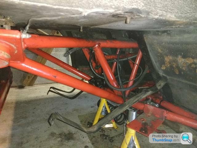
Further work on the diff. Props shaft joint now disconnected, but a fair cup of diff oil came out of the flange joint so I'm guessing the pinion flange seal is leaking via the lock nut. Diff oil all drained. Also drained down the brake master reservoir to get the lines clear of brake fluid and managed to disconnect and pull the 3m flexible brake line all the way back to the diff. Handbrake cable disconnected and diff top mounts also slackened with my new skinny spanner. So tomorrow it's angle grinder time, cutting off the rear and front diff carrier bolts which are totally galvanised and 2 pack epoxied into position. Obviously during the previous rebuild Peninsular had the chassis blasted, galvanised and epoxy painted with the diff carrier in place, and then loaded up the diff and dropped the body back on.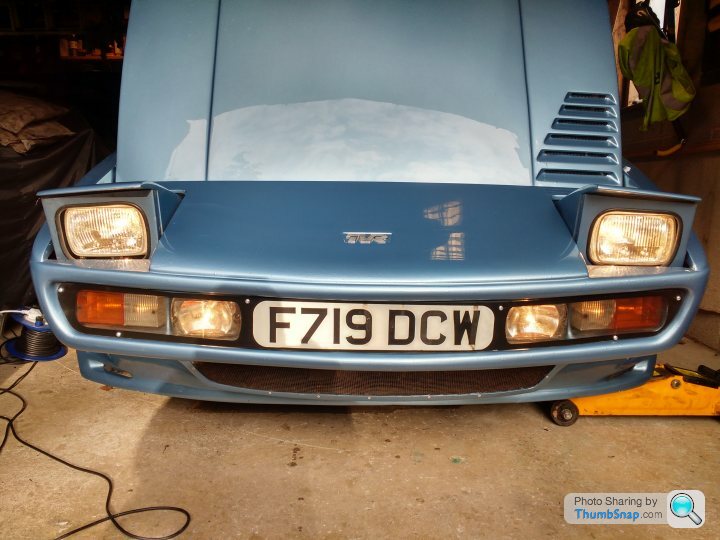
Further work on the diff. Props shaft joint now disconnected, but a fair cup of diff oil came out of the flange joint so I'm guessing the pinion flange seal is leaking via the lock nut. Diff oil all drained. Also drained down the brake master reservoir to get the lines clear of brake fluid and managed to disconnect and pull the 3m flexible brake line all the way back to the diff. Handbrake cable disconnected and diff top mounts also slackened with my new skinny spanner. So tomorrow it's angle grinder time, cutting off the rear and front diff carrier bolts which are totally galvanised and 2 pack epoxied into position. Obviously during the previous rebuild Peninsular had the chassis blasted, galvanised and epoxy painted with the diff carrier in place, and then loaded up the diff and dropped the body back on.
Edited by KKson on Friday 11th October 23:46
A fairly productive weekend on the SEAC. Friday had the headlamp sorted as above.
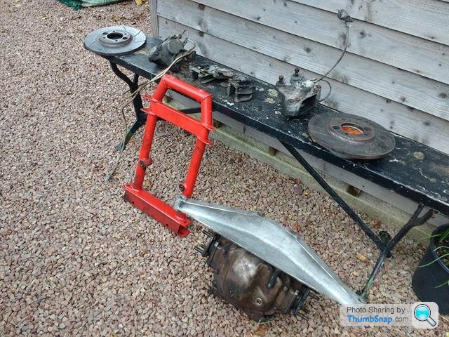
Most of Saturday was spent continuing with the diff removal. The diff carrier had been fitted prior to galvanising and epoxy coating the chassis and in addition I found that the rear carrier bolts had been tacked welded into position just to make life more difficult. Eventually with the use of a suitable angle grinder the diff and carrier were out and it then took less than 15 minutes to strip the calipers, handbrake assemblies and discs off. With a bit of wire brushing the discs have come up great so just the calipers to rebuild.

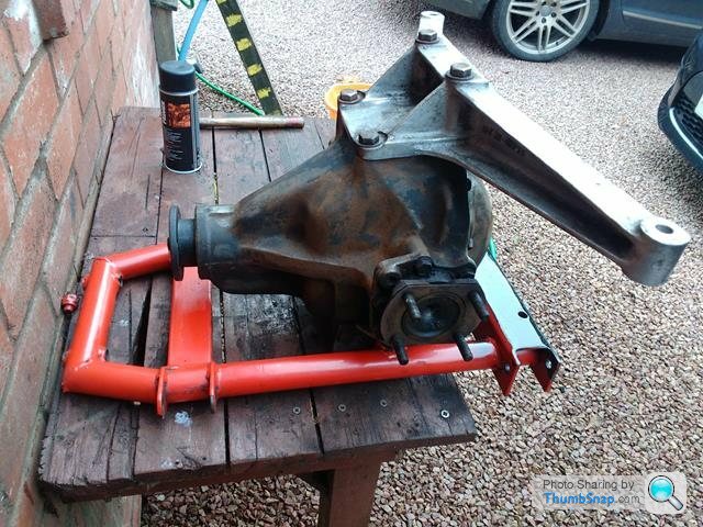
During the disassembly I did note quite a volume of diff oil escaped from the diff pinion flange centre. When I stripped the bits and pieces off the diff I noticed that the pinion lock nut was less than finger tight with some movement on the pinion flange. My dilemna now is do I send the diff off and get it rebuilt or do I risk trying to gently tighten up a new lock nut and hope I don't go too far with the pre-load. I have messaged a local transmission repairer for their advice on this one.


As I had to cut the rear diff carrier bolts out, one of them in particular was well rusted into the chassis support. No amount of hammering or penetrating oil would budge it so 2 hours were spent today very carefully drilling it out. I will need to MIG weld the rear chassis a little were the angle grinder touched the plate, but overall happy with the weekends progress.
Most of Saturday was spent continuing with the diff removal. The diff carrier had been fitted prior to galvanising and epoxy coating the chassis and in addition I found that the rear carrier bolts had been tacked welded into position just to make life more difficult. Eventually with the use of a suitable angle grinder the diff and carrier were out and it then took less than 15 minutes to strip the calipers, handbrake assemblies and discs off. With a bit of wire brushing the discs have come up great so just the calipers to rebuild.
During the disassembly I did note quite a volume of diff oil escaped from the diff pinion flange centre. When I stripped the bits and pieces off the diff I noticed that the pinion lock nut was less than finger tight with some movement on the pinion flange. My dilemna now is do I send the diff off and get it rebuilt or do I risk trying to gently tighten up a new lock nut and hope I don't go too far with the pre-load. I have messaged a local transmission repairer for their advice on this one.
As I had to cut the rear diff carrier bolts out, one of them in particular was well rusted into the chassis support. No amount of hammering or penetrating oil would budge it so 2 hours were spent today very carefully drilling it out. I will need to MIG weld the rear chassis a little were the angle grinder touched the plate, but overall happy with the weekends progress.
A fascinating read so far, episode-by-episode.
Certainly provides inspiration and confidence, especially to someone who is interested but lacking in confidence to have developed such professionally-sussed skills.
All power to your elbow(s) and looking forward to further instalments, thanks!
Certainly provides inspiration and confidence, especially to someone who is interested but lacking in confidence to have developed such professionally-sussed skills.
All power to your elbow(s) and looking forward to further instalments, thanks!
Well I've had a bit of a break from the SEAC as I've been in Cyprus visiting my sister. But back to the garage today.
First task was a 2 hour drive to drop the diff off for a professional rebuild. I was contemplating having a go at nipping up the pinion nut myself however as the crown wheel and pinion gears are no longer available common sense prevailed. Diff is having a full rebuild, bearings, seals, etc for £350 plus the VAT.
When I got home the plan was to fire up the welder and repair the slightly butchered chassis which was attacked when trying to get the welded in diff bolts out. Was about to fire up the MIG but there was a definite smell of fuel so decided that I should investigate.
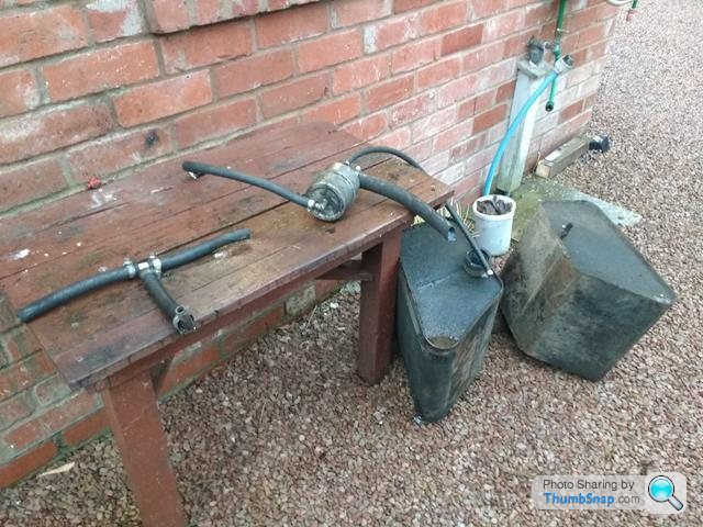
I was planning to replace all hoses anyway. The main 2" fuel filler flexible was hidden behind a riveted-in plate. Once I'd removed it I could see that the hose was well perished. Also the fuel tanks straps looked tatty so rather than mess about I thought it easy to remove the tanks and all hoses.

Prior to removal, I drained all the old fuel out of the tanks. There was no noticeable muck in the tanks but I will give them a thorough flush prior to re-installing. I've also measured all lines and penciled a flow chart of where everything goes so I've got a record for the future. Fuel lines are a mixture of 3/8", 5/8", 25mm and 2".
Everything came out without issue. So much simpler when there's no rear suspension, diff or diff carrier!


Out tomorrow taking to lad to have a look at Leeds University but Sunday it will be welding repair to the chassis and cleaning of the fuel tank exterior, straps and swirl pot.
First task was a 2 hour drive to drop the diff off for a professional rebuild. I was contemplating having a go at nipping up the pinion nut myself however as the crown wheel and pinion gears are no longer available common sense prevailed. Diff is having a full rebuild, bearings, seals, etc for £350 plus the VAT.
When I got home the plan was to fire up the welder and repair the slightly butchered chassis which was attacked when trying to get the welded in diff bolts out. Was about to fire up the MIG but there was a definite smell of fuel so decided that I should investigate.
I was planning to replace all hoses anyway. The main 2" fuel filler flexible was hidden behind a riveted-in plate. Once I'd removed it I could see that the hose was well perished. Also the fuel tanks straps looked tatty so rather than mess about I thought it easy to remove the tanks and all hoses.
Prior to removal, I drained all the old fuel out of the tanks. There was no noticeable muck in the tanks but I will give them a thorough flush prior to re-installing. I've also measured all lines and penciled a flow chart of where everything goes so I've got a record for the future. Fuel lines are a mixture of 3/8", 5/8", 25mm and 2".
Everything came out without issue. So much simpler when there's no rear suspension, diff or diff carrier!
Out tomorrow taking to lad to have a look at Leeds University but Sunday it will be welding repair to the chassis and cleaning of the fuel tank exterior, straps and swirl pot.

Hi Mark, certainly going to fit a new sender unit while the tanks are out. The previous owner did say that he only got a short run before the gauge read empty so he never did more than 100 miles between fill ups. Given the 25mm cross pipe between the two tanks I can't see that there would be much difference in level. The tanks are jointly connected at the bottom but also twin vented at the top so they should act as one tank, especially given the thin nature of petrol.
Anyone know the source of the original fuel sender?? Cheers.
Anyone know the source of the original fuel sender?? Cheers.
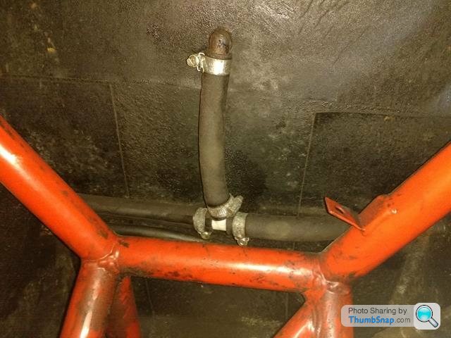
Hi Mark, no that looks like a spare that does nothing and has been blocked off. It's directly under the filler neck. At the bottom and lower point of each tank is a 25mm outlet that connects via the swirl pot to the bottom of the other tank. On the top of each tank, facing each other is a 5/8" connection. The T of rubber on my outside table seen in the photo connects these two, plus this then breathes through the boot floor and back to the filler neck.
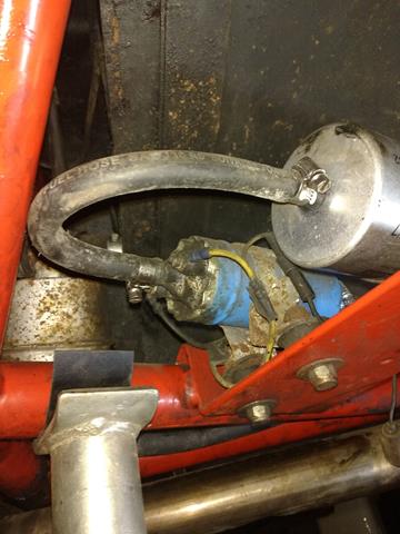
The swirl pot connects via a 5/8" tube to the pump, then 3/8" to the filter and then 3/8" to the Efi system. The Efi return line goes into the near side tank, on a similar tank connection as the blanked one. The swirl pot also has a breather that also connects on a separate 3/8" connector to the near side tank. I've sketched it all out but will do a tidy drawing for reference for others if they are interested. Cheers.
The swirl pot connects via a 5/8" tube to the pump, then 3/8" to the filter and then 3/8" to the Efi system. The Efi return line goes into the near side tank, on a similar tank connection as the blanked one. The swirl pot also has a breather that also connects on a separate 3/8" connector to the near side tank. I've sketched it all out but will do a tidy drawing for reference for others if they are interested. Cheers.
Gassing Station | Wedges | Top of Page | What's New | My Stuff