Ignition circuit
Discussion


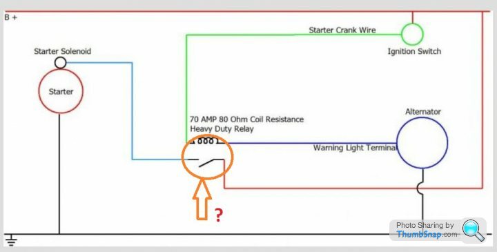
What is the purpose of the switch shown in this diagram?

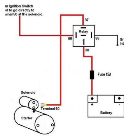
In any event, this is how your relay will most likely be connected...
My advice, for what it's worth, is to stop bu ering about with theoretical diagams, AVO's and such like and do a couple of simple Janet & John tests to find out where exactly the problem is.

In any event, this is how your relay will most likely be connected...
My advice, for what it's worth, is to stop bu
ering about with theoretical diagams, AVO's and such like and do a couple of simple Janet & John tests to find out where exactly the problem is.I agree with V8s, as what's the point in relaying a relay.
The starter solenoid has x2 jobs.
Convert electro magnetics into mechanical movement (ie. Engage the starter gear).
Operate a contactor (relay contacts) to operate the starter motor.
So as has been said previously, find and fix the fault.
IMHO, there's no need to add any additional circuitry, so don't.
Alan Whitaker said:
The wires from my ignition switch are only .5 mm cables, not enough to connect direct to the starter so I use a relay, just like in Pitstops drawing......
Hi Alan - I'm happy to stand corrected here but my interpretation of that "pitstop" diagram would mean that if you have followed it then you have in fact connected your light gauge wire from the ignition switch direct to the starter and that is now the wire which is taking the full load to the starter solenoid when you turn the key.Compare the "pitstop" diagram with the 3D drawing below it and you'll see the difference. In the 3D drawing, the low current supply from the ignition switch triggers the relay which connects the high load supply to the starter. In this arrangement the high load goes nowhere near the ignition switch.
Did you fit the in-line switch as well? What does it do? Some sort of security device?
Edited by v8s4me on Monday 3rd February 09:40
Think I have just gone to ground on the relay, it works like that, I guess it would work both ways.
On a PS, I think the switch on Pitstops drawing is the relay 30 and 87, just shown as a switch. the bit I found I could not figure out was the bit to the alternator, the warning light terminal so I just grounded the relay.
I could be wrong on this.
On a PS, I think the switch on Pitstops drawing is the relay 30 and 87, just shown as a switch. the bit I found I could not figure out was the bit to the alternator, the warning light terminal so I just grounded the relay.
I could be wrong on this.
Edited by Alan Whitaker on Monday 3rd February 10:27
GreenV8S said:
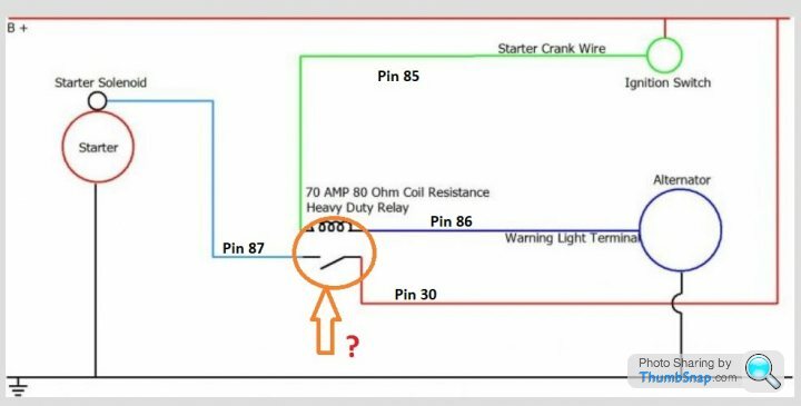
....The coil and switch are the standard representation of a relay in an electrical circuit - the numbers on the wires leading to it correspond to the relay terminal numbers.
Ah, that explains it. There weren't any numbers on the original picture. But why does the red wire (B+) go to the ignition switch? Isn't this one supposed to be the higher amperage supply to the solenoid via 30 & 87 on the relay? Why use the same heavy cable to the ignition switch if you're using a relay?Alan Whitaker said:
.... I think the switch on Pitstops drawing is the relay 30 and 87, just shown as a switch. the bit I found I could not figure out was the bit to the alternator, the warning light terminal so I just grounded the relay....
As per the 3D drawing then? v8s4me said:
....My advice, for what it's worth, is to stop buering about with theoretical diagams, AVO's and such like and do a couple of simple Janet & John tests to find out where exactly the problem is.
Then fix the problem. Sorted ering about with theoretical diagams, AVO's and such like and do a couple of simple Janet & John tests to find out where exactly the problem is.
Edited by v8s4me on Monday 3rd February 15:56
Edited by v8s4me on Monday 3rd February 18:02
v8s4me said:
Why use the same heavy cable to the ignition switch if you're using a relay?
It isn't my diagram, but I guess the author was trying to show that you would repurpose the existing wire between the switch and the solenoid.The concept of adding a relay between the switch and the solenoid is not novel and is often done on TVRs.
However, that circuit also seems to be trying to use the alternator trigger wire to operate that relay, and that strikes me as a bad idea. The alternator can produce a significant voltage at cranking speed and this would reduce the relay clamping current. Might be OK, but it's a risk I'd rather do without and there's really no reason for it. It's not as if we are in the habit of trying to engage the starter while the engine is running.
GreenV8S said:
...However, that circuit also seems to be trying to use the alternator trigger wire to operate that relay, and that strikes me as a bad idea. ....
It struck me as a bad idea as well but I didn't have the technical knowledge to know why.The diagram should really look something like this...
Which is a very confusing way of showing what the 3D diagram shows clearly.
Sandgrounder must be really confused by now. Or should that be relay confused?
Alan Whitaker said:
Think I have just gone to ground on the relay, it works like that, I guess it would work both ways.
On a PS, I think the switch on Pitstops drawing is the relay 30 and 87, just shown as a switch. the bit I found I could not figure out was the bit to the alternator, the warning light terminal so I just grounded the relay.
I could be wrong on this.
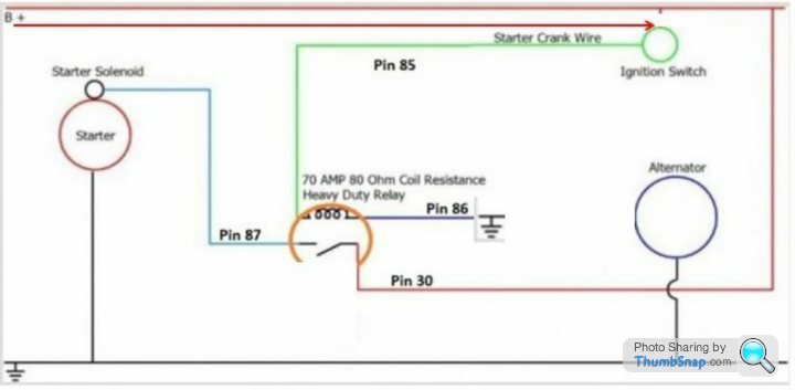
Yes that's it as in your above diagram Alan, the only problem that could arise is if the relay had a diode across the coil for Back-EMF protection the diode would blow, hence it's best practice to switch supply to 86 and earth 85On a PS, I think the switch on Pitstops drawing is the relay 30 and 87, just shown as a switch. the bit I found I could not figure out was the bit to the alternator, the warning light terminal so I just grounded the relay.
I could be wrong on this.
I really should have numbered those relay terminals when drawing the diagram.....silly me
As for the alternator wiring
The relay earths through the alternator warning light circuit which is of full negative polarity when the alternator is stationary and positive polarity when the alternator has cut-in and started charging (engine running)
The relay can be earthed at the instrument cluster alternator warning light cable or directly to the alternator warning light terminal which should be numbered 61 or D+
Have wired many of these without problems and saved many a starter pinion from being smashed to bits when a nipper presses the start button with engine running
Maths, it's all about doing the maths to help understand how the alternator circuit works
Quickly and roughly calculated below
Starter cranking speed could be 2500 to 3000 RPM
Starter pinion to flywheel ring gear could be 15/20 to 1
Will go for something like worst scenario
Good starter = 3000 RPM
Highest toothed starter pinion = Ratio of 15 to 1
3000 ÷ 15 = Engine cranking speed of 200 RPM
TVR alternators cut-in speed = approx 1000 RPM
Engine crank pulley say 6"
Alternator pulley 2"
Engine to alternator RPM = Ratio of 1 to 3
Engine cranking speed of 200 RPM = Alternator cranking speed of 600 RPM
Alternator is nowhere near its cut-in speed and starter will crank away
There's more though
12 volt relays will pull-in at something in the region of 7 to 8 volts
12 volt relays will not drop out until something in the region of 3 volts or less, sometimes lower that 2 volts, even if the drop out voltage was 5 volts it wouldn't make this circuit fall over
The thing is battery voltage when cranking will be approx 9.6/10 volts and even if an alternator had a 10 watt warning light to bring it's cut-in RPM down and managed to generate........Lets say 5 volts at 600 RPM......There would still be 5 volts across the relay coil to hold it in
Done the above using best figures to try and break the circuit but can't break it
In practice the figures would very likely be more in the circuits favour
Yamas from Greece
Penelope Stopit said:
This.....can be prevented from happening if starter and ignition relays are fitted and wired.....
I'm afraid not. My car and many others with relays in the high load circuits succumb to the "dreaded yellow connector". These crappy connectors burn out simply because they weren't up to the job in the first place. 
Finally found time to put my S3 on ramps and see if I can trace the starter problem.
Been suffering with 7 or 8 attempts to start lately as I just wanted to get a few miles on the car.
I tried the jump lead direct from Starter to battery -ve, no joy, just the same click when turning ignition on so can rule out bad earth.
Decided to take starter and battery out to do a bench test, but when I connected everything up, the starter did nothing.
Put battery on charge to make sure full voltage available.
With battery fully charged (13.3 Volts according to multimeter) tried starter again, nothing!
So, pulled my old starter out of the spares bin and connected that up. Solenoid clicking in and out, with no spin - same symptom that made me purchase a reconditioned starter.
So, I now have 2 starters, one (the newer one) totally lifeless, and the other (older one) with a functioning solenoid, but not spinning.
Other than taking both starters to someone who knows about starters to see if they really are knackered, I'm at a loss, but that will clearly have to wait until all this madness is over!!.
Gassing Station | S Series | Top of Page | What's New | My Stuff