Red Pektron relay for SEAC
Discussion


I think this is playing up in my 420 SEAC. I don't know if its a common wedge part or something different to the norm. It is the red relay in the corner of the fuse board. It seems to control the fuel pump - when it feels like it. I haven't starting phoning around yet but does anybody know the best place to get a new one from? Thank you
Every flapper wedge or flapper range rover (pre hotwire) has got one, should be easy enough to get from a motor factors, its called a steering module!
I think I may have a spare in a box of old bits but wouldn't like to say I can find it or that it is any good, if you really get stuck I'll go looking.
I think I may have a spare in a box of old bits but wouldn't like to say I can find it or that it is any good, if you really get stuck I'll go looking.
pjtvr390se said:
Every flapper wedge or flapper range rover (pre hotwire) has got one, should be easy enough to get from a motor factors, its called a steering module!
I think I may have a spare in a box of old bits but wouldn't like to say I can find it or that it is any good, if you really get stuck I'll go looking.
For some reason I'm sure my 400SE flapper has not got one.I think I may have a spare in a box of old bits but wouldn't like to say I can find it or that it is any good, if you really get stuck I'll go looking.
pjtvr390se said:
Every flapper wedge or flapper range rover (pre hotwire) has got one, should be easy enough to get from a motor factors, its called a steering module!
I think I may have a spare in a box of old bits but wouldn't like to say I can find it or that it is any good, if you really get stuck I'll go looking.
Thanks for the offer of letting me have your old one. After great difficulty the only place I seemed to be able to find one was TVR Car Parts - thanks Neil. I'll plug it in this weekend and see if I can wake the sleeping beast. Am I confident? Well.......not exactly....I think I may have a spare in a box of old bits but wouldn't like to say I can find it or that it is any good, if you really get stuck I'll go looking.
Ian350 said:
I think this is playing up --- It is the red relay in the corner of the fuse board. It seems to control the fuel pump - when it feels like it.
It may help you to understand how the steering module does its work.Introduction and Location
The Rover SD1 Efi Steering Module activates the Main (Efi) and Fuel Pump relays in a safe sequence and routes power to other key components.
Mounted on the smaller bracket with the relays behind the passenger glove box, it usually has a red plastic cover.
The Main and Fuel Pump Relays are intimately involved with the purpose and function of the Steering Module.
Circuit Diagram
This shows component connections together with their identity in the adjacent list. The Efi Steering Module derives its name from its function of routing power according the mode of operation.
Component Identity
SM Steering Module
MR Main relay
FPR Fuel Pump relay
BATT Battery
IS Ignition switch
FP Fuel Pump
EAV Extra air valve
AFM Air flow meter

Operation
The white (W) wire from the ignition switch supplies power through the right hand diode in the Steering Module (terminals 4 to 1) seen above. From there it connects to terminal 85 of the Main relay, through the relay windings to earth via terminal 86 to close the contacts when energised.
Power is now available directly from the battery via terminals 30/51 and 87 to the air flow meter (Fuel Pump contacts), Pin 10 of the ECU and to the Power Resistors which connect to the fuel injectors. However, current can only energise the injectors when the ECU completes their circuits to earth with appropriately timed injection pulses.
The Fuel Pump relay is also activated through the Steering Module but in two different modes. Initially, in engine cranking mode, power is available to the Steering Module terminal 3 via the white/red (WR) wire from the ignition switch cranking circuit. Then, as the engine starts, in engine running mode, power reaches terminal 2 via the blue/purple (UP) wire coming from the now closed Fuel Pump contacts inside the Air Flow Meter, also connected to Pin 20 of the ECU.
In either mode, current passes from the Steering Module via the respective diodes at terminal 5 to the Fuel Pump relay terminal 85, through the relay windings to earth. The closed relay contacts operate both the Fuel Pump and the Extra Air Valve with power drawn from the ignition switch.
These two diodes, by their nature of preventing current from flowing in the reverse direction, ensure that operating current from terminal 3 cannot pass to terminal 2 and vice versa.
In summary, the Fuel Pump is initially energised in the cranking mode but as soon as the engine draws air through the air flow meter its internal Fuel Pump contacts close, completing the alternative circuit to keep the Fuel Pump energised until either the ignition is switched off or the engine stalls, the Air Flow Meter flap closes, thus opening its internal Fuel Pump contacts.
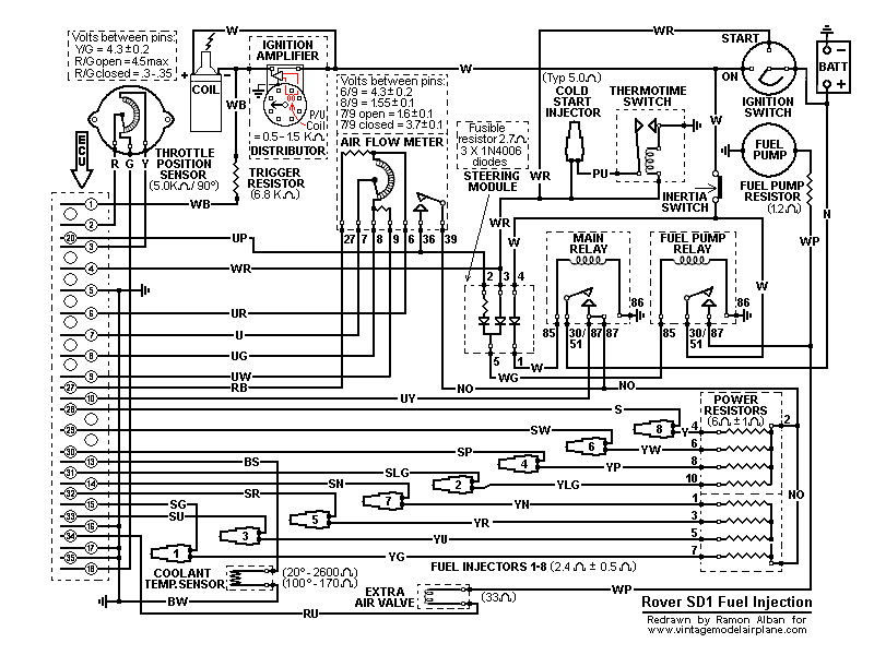
The above operational description is limited to the immediate circuitry of the subject components but a complete Rover SD1 Efi circuit diagram may also help:
Reliabilty and Replacement
Components in the Rover SD1 Efi System have varying degrees of reliability but the Steering Module has proved, over time, to be a very robust item not prone to chronic failure. One hears anecdotal evidence of failure but they seem to coincide with injudicious poking around with meter probes elsewhere in the system that cause short circuits capable of damaging the internal diodes.
The diodes, type 1N4006, are straight forward items readily available from semiconductor vendors at low cost and can be easily tested/replaced. However the fourth component in the module is an unusual fusible resistor, rated at 2.7 Ohms. Because it is an ECU protection and safety item it must be replaced "like for like". Replacements are inexpensive but will be harder to find.
To that end, and due to low failure rate, one often sees used Modules and Relays at Club Spares Days. Also SD1 Ebayers and Land/Range Rover S/H spares suppliers would readily provide them.
Conclusions
Because of its strange name and relative inaccessibility, the Steering Module and the associated relays have a reputation of unwarranted mysticism, whereas, in fact, it simply makes sure that the Main and Fuel Pump relays operate correctly and safely during the cranking and running modes.
There is loads more about the Flapper Efi system here
Thanks Honestjohn, I'll be studying this in great detail.
Needless to say I plugged the new relay in and ..... still dead. So I called the mobile auto electrician again and arranged a day for him to visit. He was amazed that the new relay hadn't fixed it. I checked the SEAC on quite a few days in the run up to make sure it was still the same and nothing had changed. Then, on checking everything was ready for the guy literally the night before, it roared into life. I then swapped the old relay back in, turned the key and everything's working again - with the old component.
Strangely, I should have been furious, but that noise that I hadn't heard for so long was just glorious!
Ian350 said:
Needless to say I plugged the new relay in and ..... still dead ---- still the same and nothing had changed. Then ----- it roared into life ---- swapped the old relay back in, turned the key and everything's working again - with the old component ----- just glorious!
Sadly, I fear the glory may be short-lived, because examining your actions, you actually did - er - nothing. 
Well, not quite nothing. You plugged the module into its socket a few times and - bingo - a dodgy contact thereabouts is now working! It's a miracle!
You may have heard that approx 80% of RV8 Efi issues are caused by local electrical connection problems and/or rogue air-leaks into the plenum chamber.
Usually the cost of fixing these problems is nil and totally at odds with the grief experienced because of them - as you now know.
If you want to prevent recurrence then there is a slightly outdated program of things you can do
http://www.vintagemodelairplane.com/pages/Download...
which covers item 13 here
http://www.vintagemodelairplane.com/pages/Snippets...
Edited by honestjohntoo on Friday 4th November 18:45
honestjohntoo said:
t may help you to understand how the steering module does its work.
Introduction and Location
The Rover SD1 Efi Steering Module activates the Main (Efi) and Fuel Pump relays in a safe sequence and routes power to other key components.
Mounted on the smaller bracket with the relays behind the passenger glove box, it usually has a red plastic cover.
The Main and Fuel Pump Relays are intimately involved with the purpose and function of the Steering Module.
Circuit Diagram
This shows component connections together with their identity in the adjacent list. The Efi Steering Module derives its name from its function of routing power according the mode of operation.
Component Identity
SM Steering Module
MR Main relay
FPR Fuel Pump relay
BATT Battery
IS Ignition switch
FP Fuel Pump
EAV Extra air valve
AFM Air flow meter
Operation
The white (W) wire from the ignition switch supplies power through the right hand diode in the Steering Module (terminals 4 to 1) seen above. From there it connects to terminal 85 of the Main relay, through the relay windings to earth via terminal 86 to close the contacts when energised.
Power is now available directly from the battery via terminals 30/51 and 87 to the air flow meter (Fuel Pump contacts), Pin 10 of the ECU and to the Power Resistors which connect to the fuel injectors. However, current can only energise the injectors when the ECU completes their circuits to earth with appropriately timed injection pulses.
The Fuel Pump relay is also activated through the Steering Module but in two different modes. Initially, in engine cranking mode, power is available to the Steering Module terminal 3 via the white/red (WR) wire from the ignition switch cranking circuit. Then, as the engine starts, in engine running mode, power reaches terminal 2 via the blue/purple (UP) wire coming from the now closed Fuel Pump contacts inside the Air Flow Meter, also connected to Pin 20 of the ECU.
In either mode, current passes from the Steering Module via the respective diodes at terminal 5 to the Fuel Pump relay terminal 85, through the relay windings to earth. The closed relay contacts operate both the Fuel Pump and the Extra Air Valve with power drawn from the ignition switch.
These two diodes, by their nature of preventing current from flowing in the reverse direction, ensure that operating current from terminal 3 cannot pass to terminal 2 and vice versa.
In summary, the Fuel Pump is initially energised in the cranking mode but as soon as the engine draws air through the air flow meter its internal Fuel Pump contacts close, completing the alternative circuit to keep the Fuel Pump energised until either the ignition is switched off or the engine stalls, the Air Flow Meter flap closes, thus opening its internal Fuel Pump contacts.
The above operational description is limited to the immediate circuitry of the subject components but a complete Rover SD1 Efi circuit diagram may also help:
Reliabilty and Replacement
Components in the Rover SD1 Efi System have varying degrees of reliability but the Steering Module has proved, over time, to be a very robust item not prone to chronic failure. One hears anecdotal evidence of failure but they seem to coincide with injudicious poking around with meter probes elsewhere in the system that cause short circuits capable of damaging the internal diodes.
The diodes, type 1N4006, are straight forward items readily available from semiconductor vendors at low cost and can be easily tested/replaced. However the fourth component in the module is an unusual fusible resistor, rated at 2.7 Ohms. Because it is an ECU protection and safety item it must be replaced "like for like". Replacements are inexpensive but will be harder to find.
To that end, and due to low failure rate, one often sees used Modules and Relays at Club Spares Days. Also SD1 Ebayers and Land/Range Rover S/H spares suppliers would readily provide them.
Conclusions
Because of its strange name and relative inaccessibility, the Steering Module and the associated relays have a reputation of unwarranted mysticism, whereas, in fact, it simply makes sure that the Main and Fuel Pump relays operate correctly and safely during the cranking and running modes.
There is loads more about the Flapper Efi system here
Gassing Station | Wedges | Top of Page | What's New | My Stuff