Graphics interface for the 14CUX
Discussion


Steve, Robert is correct, the ROM is used in place. The board clock is only 1 MHz which is within the speed range of the ROM.
As for measuring RPM, the MPU uses this clock to measure spark to spark period in 1 uSec counts and then divides by 2 (right shifts by 1) so it becomes 2 uSec. It does this, I believe, to prevent the MSB from getting set (otherwise the MPU thinks it's a negative number. This keeps the math simple. So for a 4-stroke, 8 cyl engine, the factor works out to be 7,500,000. By the way, this divide calculation is so demanding for this ancient MPU that it is bypassed above 1950 RPM.
Robert, if you are suggesting to fool the engine into thinking it's cold, I don't think that's a good idea. The system will add a lot of extra fuel (like the choke is on).
Mark, the fueling may have been pre-calculated to start with, but I suspect everything was empirical after that. The correction for RPM is more complex than just correcting for the injectors. Engine efficiency due to intake and exhaust breathing and other factors make it a complex problem. I think that's why, when you look across the row, the number sometimes goes up when you expect it to go down.
Another point about the fuel map. Software determines a location on this map to a higher resolution that it would seem. For example, the RPM value is calculated to 8-bits, which is 256 steps and more than the 16 columns. This is also true for the load calc. The fueling point is almost always some location *between* four values on the map. Software then calculates the value at that point by interpolating between these four values. The end result is a 16-bit value.
Mark - Go for it, I’m sure your first attempt won’t be as bad as mine, I reduced the fuelling too much and as a result my car run like a bag of nails, but at least I proved the theory. My mistake was reducing the adjustment factor too much but thats how you learn. I’ve now been successfully adjusting the idle speed.
Good Luck, Steve
Good Luck, Steve
danbourassa said:
jr6yam said:
Apologies if this question is slightly O/T
What changes, if any, did TVR make to the LR maps?
Would an ECU from a later model have a better map? (mine's a 95 Chim)
There are significant changes between LR and TVR maps, so no LR maps would probably work well in your Chim.What changes, if any, did TVR make to the LR maps?
Would an ECU from a later model have a better map? (mine's a 95 Chim)

I want to mention to Steve and others who may want to experiment, that the tables in the fuel map are not nearly as complicated as would seem at first glance. Excluding the main fuel map, the top row is always the coolant sensor count value and this tells the software what column of data to use. Only one column is in play at any given engine temperature. For example, if the coolant temp count reads 0x23 (approx 190 deg F), only the second column would be in play (the next column to the right of this value). So, using the example below, if you want to tune a fully warmed engine, you are now down to just 5 values to be concerned about.
C731 : 18 31 5A 73 89 99 B3 CC DD EA    ; <-- coolant temp sensor reading (low is hot, high is cold)
C73B : 05 06 08 0A 10 1C 23 28 30 30    ; <-- throttle opening (compare value or limit)
C745 : 04 06 07 08 08 00 00 00 00 00    ; <-- throttle closing (compare value or limit)
C74F : 2D 32 3C 50 64 FF FF FF FF FF    ; <-- throttle opening (multiplier)
C759 : 1C 18 10 0C 0B 14 14 19 19 19    ; <-- throttle opening (multiplier)
C763 : 24 18 10 0C 0B 1E 1E 1E 1E 1E    ; <-- throttle closing (multiplier)
danbourassa said:
Dave Peck? It's good to hear from you and I'm glad you're still interested in this stuff. There's still a lot of cracking to do.
Yeah, still up to my neck in Op codes and Operands. Trying to find a basic flow at the moment. Looks like you guys are making good progress.Colin came over yesterday. The FPGA idea I mentioned earlier is out. The main problem was getting the part we need in 5 volts. New designs are not made in 5 volt versions anymore. We have a better idea. Move the fuel map to RAM. It sounds simple but it's not.
There are only 320 bytes of RAM on the board and only about 10 unused bytes left. The fuel map is 128 bytes, plus 2 for the scaling factor (more still if we want to move the accelerator table). To do this we would need to do several things.
1) Rip out most (or all) of the diagnostics. There are locations in RAM that hold things like MIL delay counters (so an intermittent fault doesn't flash the MIL too quickly). The user would simply start with the normal PROM to assure that there are no fault codes.
2) Move other RAM variables in order to get a contiguous block of available RAM. To do this we need to convert from hard address references (due to the code being disassembled and not the original source) to floating labels. This is tedious and there's lots of opportunity to break the software.
3) Force open loop only. This will save a lot of RAM.
4) Use some sort of data compression on the fuel map. Hopefully, we can cut the size in half or smaller.
If we do this, it would no doubt be a winter time project. I just hope we don't spend months working on this and discover the "fatal flaw" in our plan.
danbourassa said:
Robert, if you are suggesting to fool the engine into thinking it's cold, I don't think that's a good idea. The system will add a lot of extra fuel (like the choke is on).
I meant changing a value in the ROM to prevent it from entering closed loop.Engine management srategies usually do not update their fuel trims when an engine is first started to avoid garbage data from a cold engine and cold o2 sensors. Its typically time and temperature. Have you seen any such thing while disassembling the code for table 5?
blitzracing said:
So what you are saying is the base fueling is already pre calculated any given rpm / load on a linear basis, and the values in the map are effectively a "trim value" over that linear preset to cope with the mechanical variances? If this is the case it really could be as simple as altering the trim values as you can now see where the load points are at any time.
---Ill try and get the RR map copied today.
That is my theory, the adjustment factor is the pre calculated fuel for the engine and the table trims it.---Ill try and get the RR map copied today.
This is really not a true mass air system, it is only using the MAF for figuring engine load. MAF systems of this vintage usually do not contain a detailed fuel map like this, just a simple 1D table that shows air mass vs sensor voltage and possibly an AFR table. The theory I've heard was back when these 1st and 2nd gen mamagement systems were designed the computing power was limited to the point where doing real time fuel requirement calculations based on the air mass just wasn't possible, so precaculated requirements in a table free up the processor to do other things.
Colin
You may be interested to see on the Griffith forum someone has customised RoverGauge for a PreCat Griff, cool idea.
http://www.pistonheads.com/gassing/topic.asp?h=0&a...
You may be interested to see on the Griffith forum someone has customised RoverGauge for a PreCat Griff, cool idea.
http://www.pistonheads.com/gassing/topic.asp?h=0&a...
Colin, Dan, Mark anyone
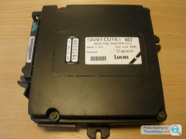
Please tell me I'm not hallucinating?? a SAAB 14CUX
Its currently on ebay http://www.ebay.co.uk/itm/Brand-new-ECU-Saab-900-T...
Please tell me I'm not hallucinating?? a SAAB 14CUX
Its currently on ebay http://www.ebay.co.uk/itm/Brand-new-ECU-Saab-900-T...
stevesprint said:
Colin, Dan, Mark anyone
Please tell me I'm not hallucinating?? a SAAB 14CUX
Its currently on ebay http://www.ebay.co.uk/itm/Brand-new-ECU-Saab-900-T...
Colin and I discussed this once. I think we determined that the bank switched architecture also supported inline fours (or fives, I don't know SAABs). I would love to see the PROM code for this. Either software would have to be tailored to drive one bank or the fault codes for the missing bank would have to be masked out. I believe this basic architecture (using the Motorola 6803U4) was used for a number of vehicles including the Ferrari F40. In that case, they used two ECUs (one for each bank). For those familiar with single plane (or flat plane) crankshaft V8s (think AJP V8), you will appreciate that the Ferrari V8 is simply two inline fours sharing a common crank.Please tell me I'm not hallucinating?? a SAAB 14CUX
Its currently on ebay http://www.ebay.co.uk/itm/Brand-new-ECU-Saab-900-T...
Somebody, please buy this and send me the binary.
danbourassa said:
Colin and I discussed this once. I think we determined that the bank switched architecture also supported inline fours (or fives, I don't know SAABs). I would love to see the PROM code for this. Either software would have to be tailored to drive one bank or the fault codes for the missing bank would have to be masked out. I believe this basic architecture (using the Motorola 6803U4) was used for a number of vehicles including the Ferrari F40. In that case, they used two ECUs (one for each bank). For those familiar with single plane (or flat plane) crankshaft V8s (think AJP V8), you will appreciate that the Ferrari V8 is simply two inline fours sharing a common crank.
Somebody, please buy this and send me the binary.
The MC6803U4-based system used in the F40 is called Weber-Marelli I.A.W., and it's also used in some Cosworth Fords, Lancia Deltas, and the Aston Martin Virage. There's lots of information on it at the BigTurbo web site. Because of the 6803U4's multiple timer outputs, it was well-suited to engine management systems designed in the 1980s and early 1990s, which explains why it appears in both the 14CUX and I.A.W.Somebody, please buy this and send me the binary.
Is this any use in place of the non programmable chip with the relevant write sigal added?
http://uk.farnell.com/atmel/at28c256-15pu/ic-eepro...
http://uk.farnell.com/atmel/at28c256-15pu/ic-eepro...
Edited by blitzracing on Monday 2nd September 19:24
cmb said:
The MC6803U4-based system used in the F40 is called Weber-Marelli I.A.W., and it's also used in some Cosworth Fords, Lancia Deltas, and the Aston Martin Virage. There's lots of information on it at the BigTurbo web site. Because of the 6803U4's multiple timer outputs, it was well-suited to engine management systems designed in the 1980s and early 1990s, which explains why it appears in both the 14CUX and I.A.W.
I remember reading that Motorola themselves published a fuel injection reference design using, I believe, this device. As if it were originally intended for fuel injection applications. I've searched for this document and, so far, have found nothing. If somebody comes across it, please share it with us. It may answer some questions.blitzracing said:
Is this any use in place of the non programable chip with the relavent write sigan added?
http://uk.farnell.com/atmel/at28c256-15pu/ic-eepro...
Even if the write signal and software mods were not done to enable writing it in place, this EEPROM is still a chip that can be used instead of the UV EPROM. They are industrial temperature range and they erase and reprogram in one step on the programmer. I use them.http://uk.farnell.com/atmel/at28c256-15pu/ic-eepro...
Hi Colin and Dan, Thank you both for keeping up your hard work over the weekend. I’m sorry to hear the FPGA idea is out; maybe you didn’t drink enough beer.  To be honest the Atmel EEPROM you and Mark mention will revolutionize my life plus I’m not even bothering to correct the checksum for my tests.
Colin also thanks for explaining the target idle issue with the early revision I’m not surprised there was a good reason and Dan thanks for confirming PROM is not copied to RAM.
Please have a look at my recent update on the Griffith pages as you may find it interesting. It would be good to keep the thread going as it seems to of created some interest.
http://www.pistonheads.com/gassing/topic.asp?h=0&a...
Cheers, Steve
To be honest the Atmel EEPROM you and Mark mention will revolutionize my life plus I’m not even bothering to correct the checksum for my tests.Colin also thanks for explaining the target idle issue with the early revision I’m not surprised there was a good reason and Dan thanks for confirming PROM is not copied to RAM.
Please have a look at my recent update on the Griffith pages as you may find it interesting. It would be good to keep the thread going as it seems to of created some interest.
http://www.pistonheads.com/gassing/topic.asp?h=0&a...
Cheers, Steve
Edited by stevesprint on Wednesday 4th September 00:32
robertf03 said:
I'm still a little fuzzy on the checksum location for the 14cux. I do not believe it is the first byte of the ROM image as that is the first entry in fuel table 0. Changing it will work, but that is a kludge. IMO, the next step is find the true checksum byte location.
Robert, I must apologize. You are correct (again)! I just got an email from a man who knows much. The checksum fixer location is at address 0xFFEB (or 0x3FEB on the programmer). This makes more sense. I have asked about why the first location was sometimes changed between upper and lower halves (which led to my confusion on this). Hopefully there will be an interesting answer.danbourassa said:
Colin and I discussed this once. I think we determined that the bank switched architecture also supported inline fours (or fives, I don't know SAABs). I would love to see the PROM code for this. Either software would have to be tailored to drive one bank or the fault codes for the missing bank would have to be masked out. I believe this basic architecture (using the Motorola 6803U4) was used for a number of vehicles including the Ferrari F40. In that case, they used two ECUs (one for each bank). For those familiar with single plane (or flat plane) crankshaft V8s (think AJP V8), you will appreciate that the Ferrari V8 is simply two inline fours sharing a common crank.
Somebody, please buy this and send me the binary.
Colin & Dan - As you declined a donation for bring us all RoverGauge I decided to buy a very cheap SAAB 14CUX and have forward you the binary as requested. Somebody, please buy this and send me the binary.
The SAAB 14CUX - Spot the differences & why?
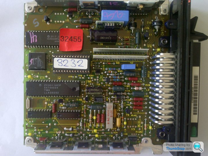
Am I correct thinking it is 14CUX based and not 14CU as it has the MVA5033KA chip? Also, could it be modified to run our favourite gang of 8? The most obvious components missing are the 2 blue capacitors and it has an extra grey capacitor instead. I’m not an electronics person so in my very basic terms I’m think maybe the missing 2 blue capacitor one for each bank & here one grey capacitor for one bank of 4.
As I don’t have cats to damage I dived in and tested this ECU with a V8 EPROM The engine actually started but was an effort to keep it running. The revs shot up to 2k and dropped repeatedly. More curiously RoverGauge failed to connect.
Next I tried the SAAB EPROM in a V8 ECU, the pump primed ok and RoverGauge connected but display incorrect data, like volts –0.1 & engine temp 135 degrees when cold, I guess because all the memory addresses are different. Anyway the engine started with a lot of throttle and was clearly run only on 4 cylinders and required a lot of throttle to keep it running.
I Finally tried the SAAB 14CUX with the SAAB EPROM, which proved to be the best combination, it actually idled on it’s own and revved freely. It was running on all eight cylinders and seemed driveable but I wasn’t brave enough. RoverGauge briefly connected before crashing.
Afterwards I reconnected my original TVR ECU and I was relieved to hear my Griff had survived. I wouldn’t advise doing that on a cat car and I don’t really want to do that again unless I thought it might help Colin and Dan.
The main lesson leant here is don’t buy a cheap SAAB 14CUX thinking it will run your gang of 8 with your original EPROM as it clearly doesn’t.
danbourassa said:
Robert, I must apologize. You are correct (again)! I just got an email from a man who knows much. The checksum fixer location is at address 0xFFEB (or 0x3FEB on the programmer). This makes more sense. I have asked about why the first location was sometimes changed between upper and lower halves (which led to my confusion on this). Hopefully there will be an interesting answer.
Dan - That location does look better as I’ve noticed the first 3 bytes are the same on all the standard bins I have and are not the same on the bins I’ve fixed the checksum. Gassing Station | General TVR Stuff & Gossip | Top of Page | What's New | My Stuff