14CUX and ignition wiring?
Discussion


We all know the available wiring diagrams are pretty useless as most of the wires terminate at some undefined connector block with nothing shown beyond that point which is why I am trying to make my own diagrams. (mini rant)
So, other diagrams of the ECU wiring (normally based on Land Rover applications) indicate there should be a resistor in the line between the coil negative and the ECU (Pin 39) but I can't see it anywhere in my wiring nor can I see it on any of the TVR diagrams.
Is it used on TVR and if so where and what value/part number?
Thanks
Steve
Steve_D said:
We all know the available wiring diagrams are pretty useless as most of the wires terminate at some undefined connector block with nothing shown beyond that point which is why I am trying to make my own diagrams. (mini rant)
I disagree. The main schematics in the 'bible' are quite good and accurate, it's simply the poor resolution that makes them hard to read. If you look at the way the diagram is laid out you'll see that the position of the symbols corresponds to where the devices are actually located on the car. The connector blocks are not undefined. Look closely at the pin labels on the schematics and you'll see that they correspond with the connector block designations on the fuse and relay panel, for example: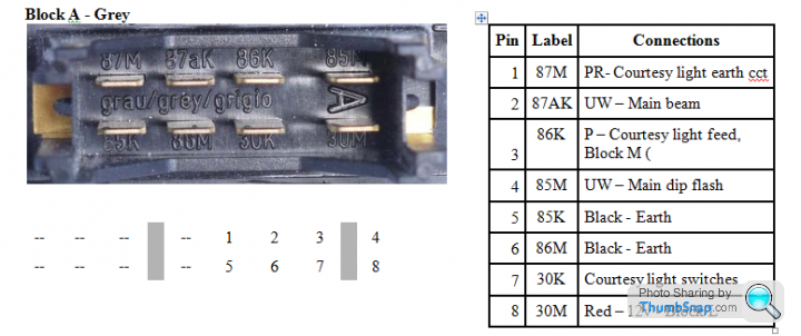
The same applies to the main RISTS connector:

..and so on.
Steve_D said:
So, other diagrams of the ECU wiring (normally based on Land Rover applications) indicate there should be a resistor in the line between the coil negative and the ECU (Pin 39) but I can't see it anywhere in my wiring nor can I see it on any of the TVR diagrams.
Is it used on TVR and if so where and what value/part number?
Thanks
Steve
The resistor is in there somewhere.Is it used on TVR and if so where and what value/part number?
Thanks
Steve
Edited by davep on Saturday 15th July 11:20
davep said:
Steve_D said:
We all know the available wiring diagrams are pretty useless as most of the wires terminate at some undefined connector block with nothing shown beyond that point which is why I am trying to make my own diagrams. (mini rant)
I disagree. The main schematics in the 'bible' are quite good and accurate, it's simply the poor resolution that makes them hard to read. If you look at the way the diagram is laid out you'll see that the position of the symbols corresponds to where they are actually located on the car. The connector blocks are not undefined. Look closely at the pin labels on the schematics and you'll see that they correspond with the connector block designations on the fuel and relay panel, for example:The same applies to the main RISTS connector:
..and so on.
Steve_D said:
So, other diagrams of the ECU wiring (normally based on Land Rover applications) indicate there should be a resistor in the line between the coil negative and the ECU (Pin 39) but I can't see it anywhere in my wiring nor can I see it on any of the TVR diagrams.
Is it used on TVR and if so where and what value/part number?
Thanks
Steve
The resistor is in there somewhere.Is it used on TVR and if so where and what value/part number?
Thanks
Steve
The connector photo and pin info you have shown is from a separate document (which I have) but is not part of the bible so my comment that the bible info is lacking is still true. Even with that additional document it does not help where a wire, for instance, goes to the Rists connector marked 'Dashboard' without showing anything beyond that so you don't know which instrument or switch the wire goes too.
Resistor...where are you?
Steve
Here you go:

That's for early Griff mind. Shouldn't be difficult to draw a schematic for the dashboard.
Here's a link to a generic fuse/relay panel interconnect diagram:
http://www.thetvrsite.com/files/wiring-diagrams/fu...
You simply have to assign relay and fuse functions according to the car you're working on, because, as you know, they do differ.
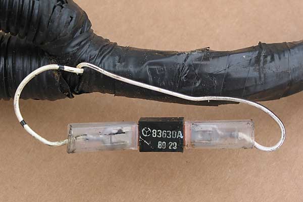
Bit more research says it is fitted near the coil and is known as FDB943 or DRC1752 or RD953066 and is 6.8K.
It may also be in the loom near the ECU but it is not in either place on my car nor is there any resistance on the line to pin 39.
The part above does not appear to be available anywhere so I will have to go and source some 6.8K ohm resistors.
I'll fit mine close to the ECU as it will be an safer location for the resistor.
Steve
Steve_D said:
Bit more research says it is fitted near the coil and is known as FDB943 or DRC1752 or RD953066 and is 6.8K.
It may also be in the loom near the ECU but it is not in either place on my car nor is there any resistance on the line to pin 39.
The part above does not appear to be available anywhere so I will have to go and source some 6.8K ohm resistors.
I'll fit mine close to the ECU as it will be an safer location for the resistor.
Steve
If your car has been running without the 6.8K Inline or dropping resistor I'd also check that the ECU's PCB is ok, especially in the area of the pin 39 input circuit.It may also be in the loom near the ECU but it is not in either place on my car nor is there any resistance on the line to pin 39.
The part above does not appear to be available anywhere so I will have to go and source some 6.8K ohm resistors.
I'll fit mine close to the ECU as it will be an safer location for the resistor.
Steve
The ECU uses the LT coil pulses coming in on pin 39 as (1) a positive edge trigger to calculate engine RPM, and (2) initiate the timer for the main fuelling interrupt. As such it is one, if not the most, important input to the ECU.
its bound into the loom sometimes- picture of it half way down the page:
http://www.britishv8.org/articles/rover-14cux-efi....
http://www.britishv8.org/articles/rover-14cux-efi....
Edited by blitzracing on Tuesday 18th July 12:16
blitzracing said:
its bound into the loom sometimes- picture of it half way down the page:
http://www.britishv8.org/articles/rover-14cux-efi....
Yes that is the place I found a couple of days ago and was the start of identifying part numbers for it.http://www.britishv8.org/articles/rover-14cux-efi....
Edited by blitzracing on Tuesday 18th July 12:16
I've still not found any so have ordered some ceramic wirewound 5w beasties.
Steve
Gassing Station | General TVR Stuff & Gossip | Top of Page | What's New | My Stuff