Stuart Twin Victoria (Princess Royal) Mill Engine
Discussion


Simpo Two said:
That is serious modelmaking!
I'll stick to wood, it's easier to cut and you don't have to heat it to 3,000C...
To be fair it was only a question of chucking in the fire for the evening and hoping for the best. It's supposed to make it cut like butter.I'll stick to wood, it's easier to cut and you don't have to heat it to 3,000C...
After the test on Friday worked, I put the whole lot in the fire last night, and got a nice even spread of fuel:

This is how they came out this morning:
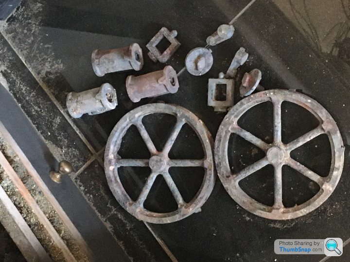
One of the cylinder caps had stuck itself to a spoke, but it pinged off after I hit it with the poker. All seems a bit medieval, but it's all good fun.
There's a hell of a long way to go with this one - especially at this rate...
No more hard spots. Now you have to leave them outside for a couple of years to de-stress, with regular “watering “. A company on the Sheepbridge Estate , Chesterfield, used to have acres of stacked cylinder liners outside, all going rusty. I think the theory was the temperature swings helped relieve the internal stresses.
fourfoldroot said:
No more hard spots. Now you have to leave them outside for a couple of years to de-stress, with regular “watering “. A company on the Sheepbridge Estate , Chesterfield, used to have acres of stacked cylinder liners outside, all going rusty. I think the theory was the temperature swings helped relieve the internal stresses.
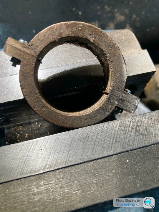
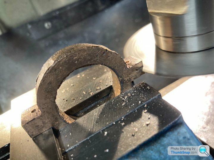
I seem to remember all the ‘80’s BMW four cylinder Turbo F1 engine blocks were from old road cars that had had all their internal stresses aged out of them.I’ve just machined this eccentric strap from a gunmetal casting. I was shocked how much it sprang apart from the released stresses when I released the bolts holding the two parts. I had to remount it and true up the bore which was a pain because it was quite spindly by then.
 [url]
[url]
 |https://thumbsnap.com/wHeBg8Ba[/url]

[url]|https://thumbsnap.com/wHeBg8Ba[/url]fourfoldroot said:
I’ve just machined this eccentric strap from a gunmetal casting. I was shocked how much it sprang apart from the released stresses when I released the bolts holding the two parts. I had to remount it and true up the bore which was a pain because it was quite spindly by then.
[url]
|https://thumbsnap.com/wHeBg8Ba[/url]
I suppose it's one of the multitude of subtleties of Model Engineering (or real engineering for that matter). You have to deal with things that you wouldn't necessarily expect to have to deal with. Decent machine tools are great, but a lot of work is dealing with things like spring cuts (ie not expecting a dial or DRO setting to correspond to a finished piece!), potential hard spots or internal stresses springing things apart. It's amazing that anything fits together at all. [url]|https://thumbsnap.com/wHeBg8Ba[/url]My workplace was initially set up for research purely into optimising machining of thin walled aerospace components and tuning out the vibrations of the parts and tools to give the fastest possible material removal rates. All sorts of clever stuff involved in terms of listening for resonances and engineering them out using dampers. So there are plenty of people to ask about machining, but the more you ask, the less you know.
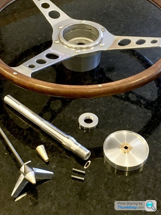
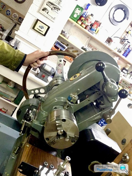
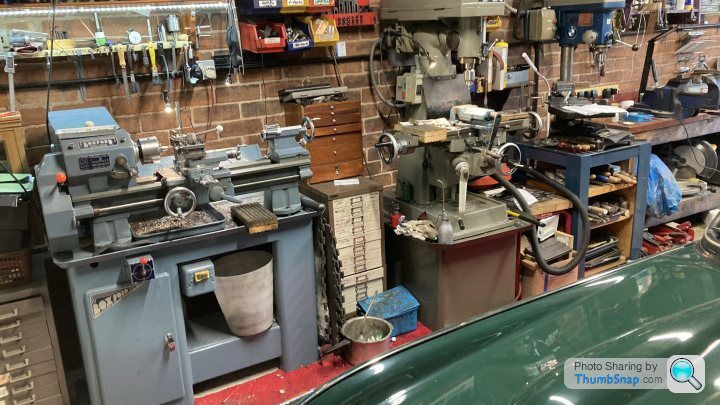
As a prelude to starting this next steam engine, I've been fettling the lathe and mill, and getting a few bits sorted that I thought would be useful for the next build. The first thing was to make a hand crank for the chuck to make threading easier. I was going to buy one, then noticed the old steering wheel hanging on the wall that my dad fitted to the MGB. When it was rebuilt, we re-fitted the original, so this one was spare. I had a brainwave and through it might even be better to have a wheel for threading rather than a crank:
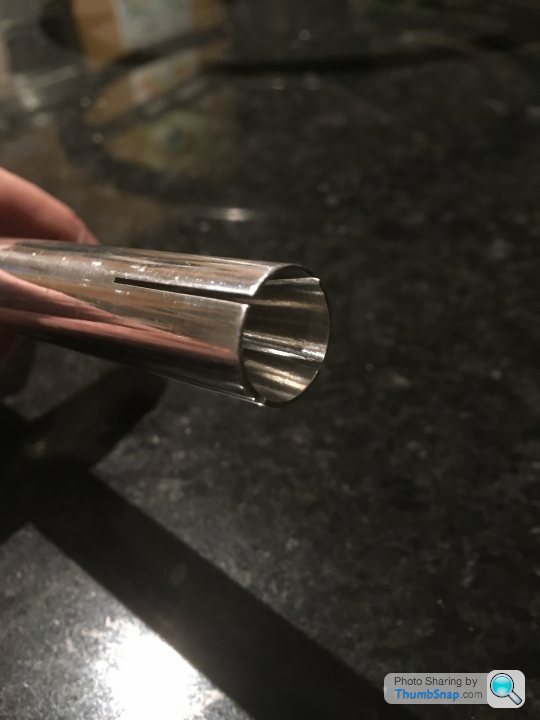
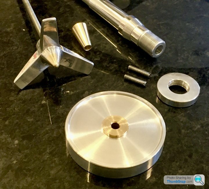
I made a split spindle to fit in the lathe shaft, and a brass cone to fit in the end to expand it and lock it in place:
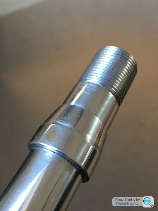
The steering wheel has a location taper, which I tried to replicate. I made the taper separately, and Loctited and through-pinned it to the shaft with brass pins, before machining flush:
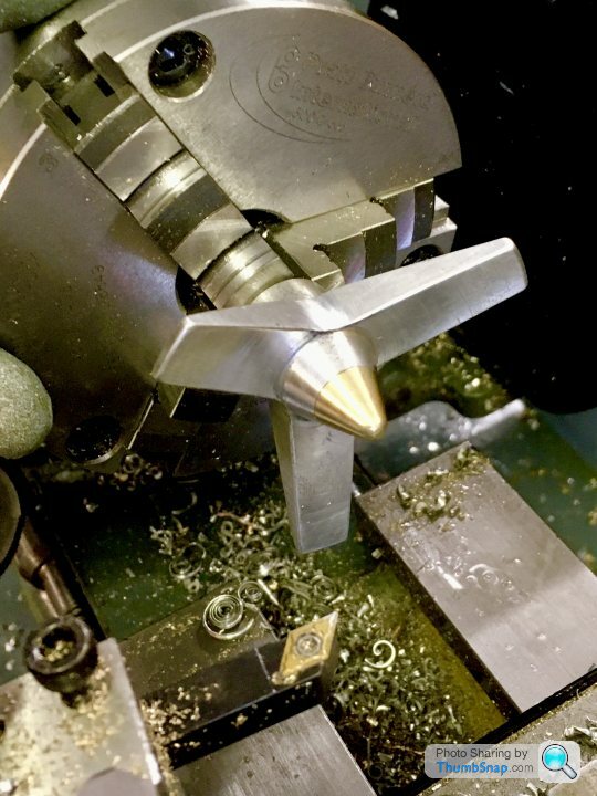
Then I needed a locking wheel to pull the cone into the shaft. I thought I go for a wheel spinner/propeller type thing to make it look a bit interesting, and be nice to use. I made one by a combination of milling and turning:
Here are the component parts I made, along with the wheel:
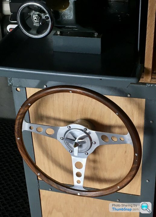
And here it is all assembled:
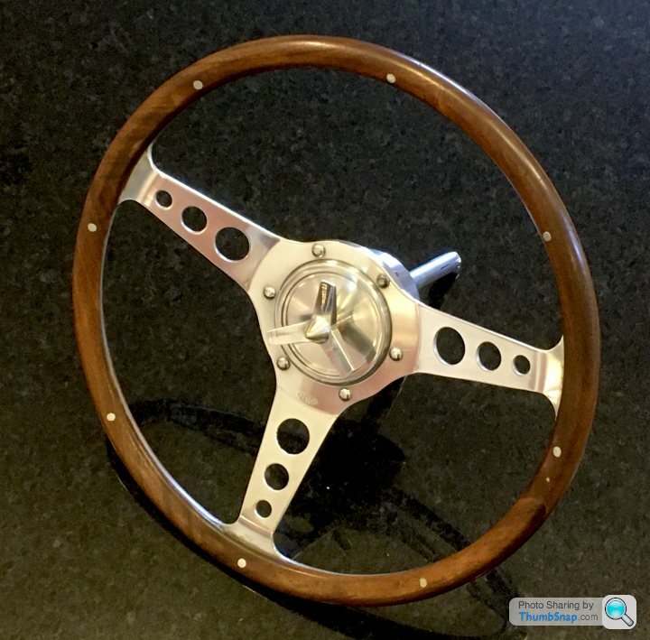
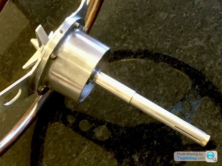

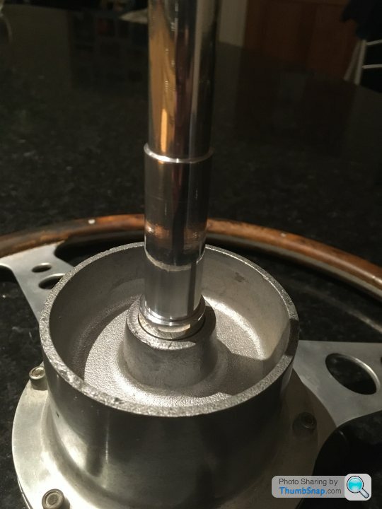
Fits very easily into the spindle, and it only takes 1/4 turn to lock it solid:

I can easily turn it while messing about at the far end of the tailstock - it works really nicely:
Also found a place to store it - in a block screwed to the inside of my lathe stand:
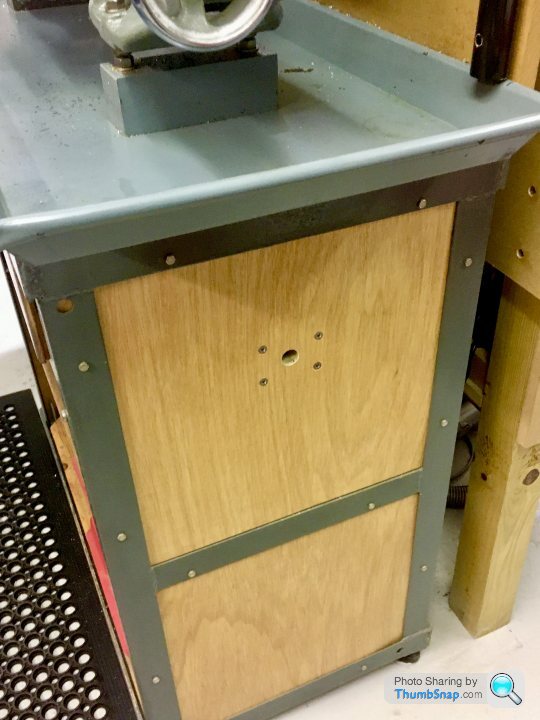
The wheel itself is un-modified, so if I decide to re-fit it to the car, no problem.
Cheers!
I made a split spindle to fit in the lathe shaft, and a brass cone to fit in the end to expand it and lock it in place:
The steering wheel has a location taper, which I tried to replicate. I made the taper separately, and Loctited and through-pinned it to the shaft with brass pins, before machining flush:
Then I needed a locking wheel to pull the cone into the shaft. I thought I go for a wheel spinner/propeller type thing to make it look a bit interesting, and be nice to use. I made one by a combination of milling and turning:
Here are the component parts I made, along with the wheel:
And here it is all assembled:
Fits very easily into the spindle, and it only takes 1/4 turn to lock it solid:
I can easily turn it while messing about at the far end of the tailstock - it works really nicely:
Also found a place to store it - in a block screwed to the inside of my lathe stand:
The wheel itself is un-modified, so if I decide to re-fit it to the car, no problem.
Cheers!
Another small thing that needed doing - milled some soft jaws for the vice out of aluminium bar. I'd started making some magnetic ones (couldn't find any good ones at a decent price), but then opted to replace the fixed steel jaws instead. Two advantages - they can't fall off at an inconvenient time, and also you can grip things right at the top edge without them pivoting themselves off the jaws. I had to make the countersinks bigger, and turn down the bolts to make sure they wouldn't touch any small diameter bar sitting within the centering grooves. Ideally they'd be aluminium screws I guess:

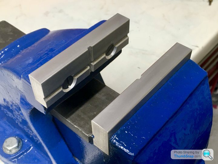

Also gave it a blow over with blue paint while I was at it.
Next...repair the home made rear toolpost I got with the lathe.
Also gave it a blow over with blue paint while I was at it.
Next...repair the home made rear toolpost I got with the lathe.
So it’s the one year anniversary of starting the 10V, so I made a start on this one. This time with some help:
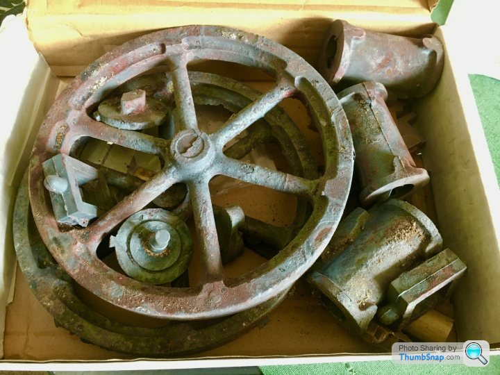
We got the castings and bed material out - shows how much work this is going to be:

After re-figuring out how all the 3D printed jigs were supposed to work, fist job was to trim the bed plate sides to length on the mill:
Small start, but it’s a start.
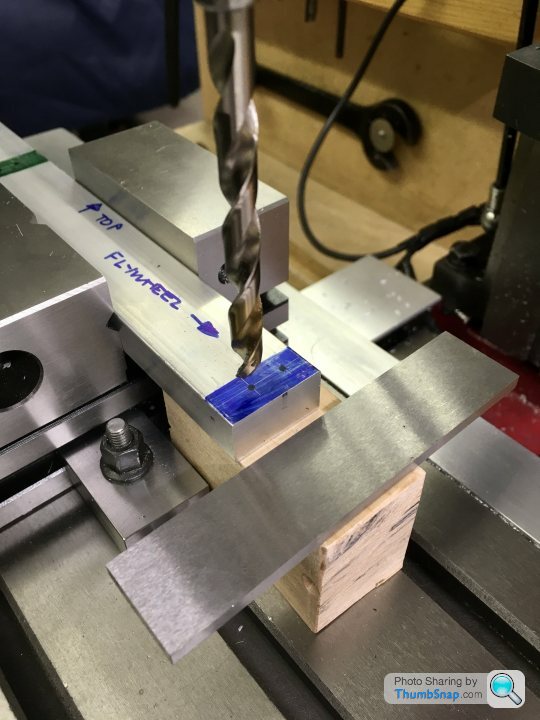
Next job is to co-ordinate drill the counterbored holes.
We got the castings and bed material out - shows how much work this is going to be:
After re-figuring out how all the 3D printed jigs were supposed to work, fist job was to trim the bed plate sides to length on the mill:
Small start, but it’s a start.
Next job is to co-ordinate drill the counterbored holes.
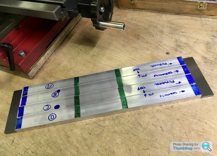
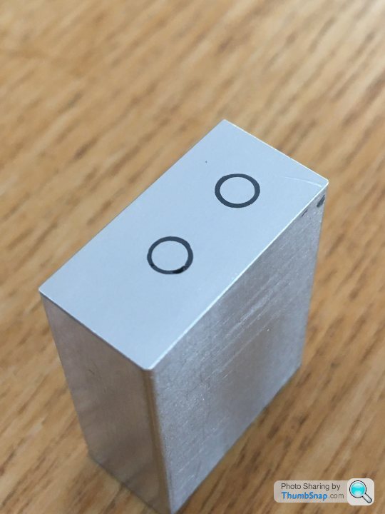
Got the holes drilled and counterbored, they all match - so far.
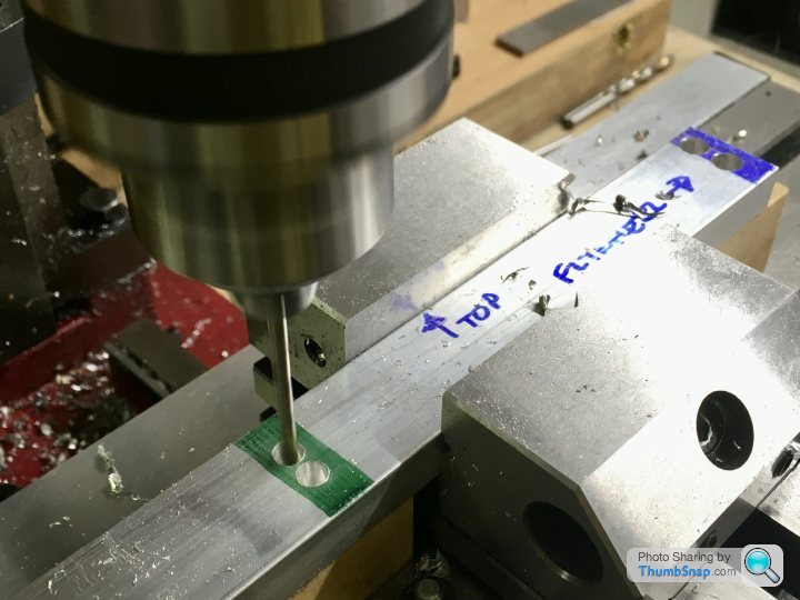
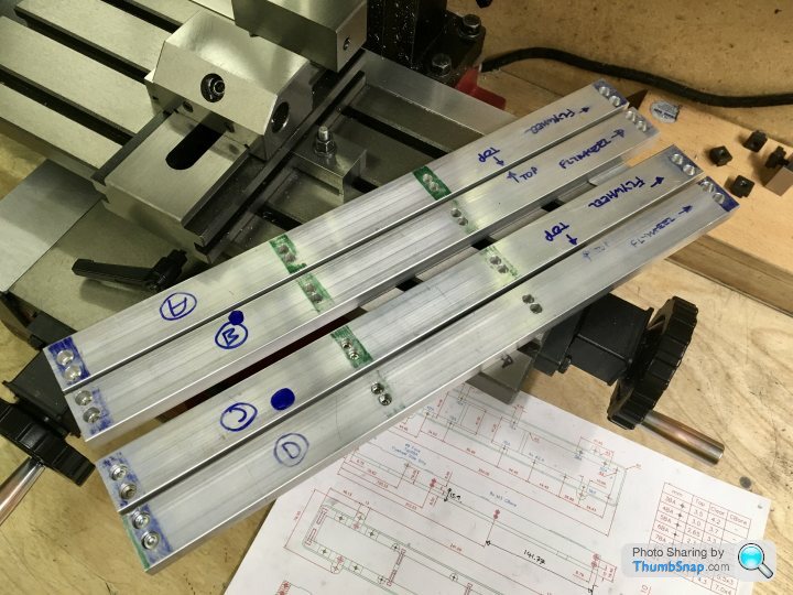
Very easy to get them mixed up, I’ll have to keep the markings clear to prevent a time consuming mistake.
Still have to drill sockets for the linkage bosses in the inner walls (B & C), then we will see if the 3D printed casting draft jigs work...
Very easy to get them mixed up, I’ll have to keep the markings clear to prevent a time consuming mistake.
Still have to drill sockets for the linkage bosses in the inner walls (B & C), then we will see if the 3D printed casting draft jigs work...
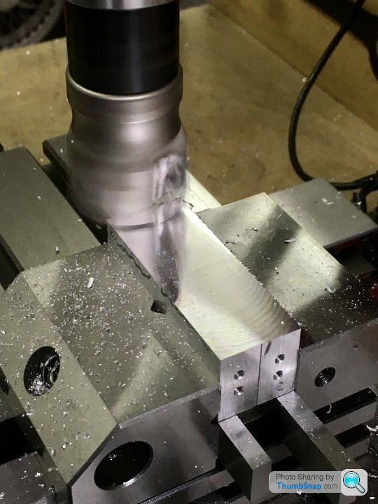
Decided to get on with the bed cross-pieces and ends. First job: saw 8x blocks a bit oversized, and de-burr:
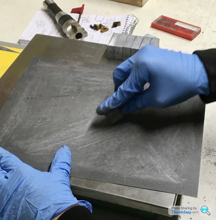
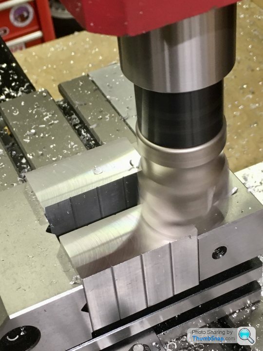
Then machine to the right width with the shell mill. This wasn’t as easy as it seemed for some reason, and took several goes to get the corners 90 degrees according to the engineer’s square:
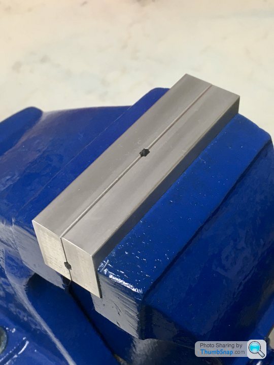
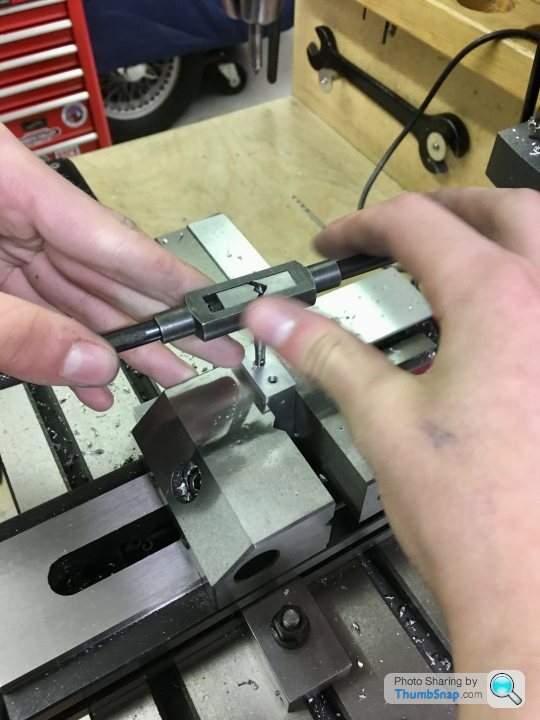
I’d machined an end stop for the vice during my dormant modelling phase, and this came in handy as a fixture for the 32 drilled and tapped holes:
Because of the way I’d designed the ends to allow for tapered outer faces, the holes aren’t on the central axis of the end pieces, they are offset inwards slightly. This tripped me up on the first piece, which gave a staggered end:
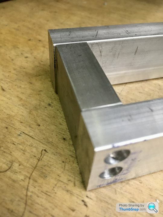
another lesson learned. I JB Welded some aluminium rod into the holes, faced off and re-drilled. It’s spot-on now.
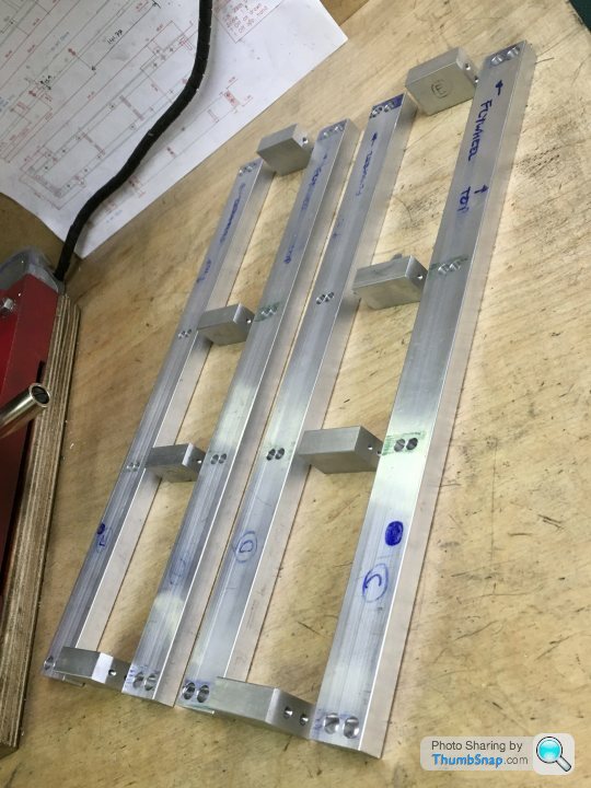
Then the middle spacers were drilled and tapped, and reduced in height by 5.4mm:
Made another error by drilling the first hole M4 as per the ends, should be M3 to accommodate the taper. Silly error, especially when using my own design/drawings. Anyway, as with the ends, I realised after the first one, and that’ll be corrected by tomorrow. So here we are now:
Next job is to disassemble again, and drill a couple of blind holes in the inner sides for the bosses for the throttle bell cranks, then it’ll be machining the tapers on all the components.
Then machine to the right width with the shell mill. This wasn’t as easy as it seemed for some reason, and took several goes to get the corners 90 degrees according to the engineer’s square:
I’d machined an end stop for the vice during my dormant modelling phase, and this came in handy as a fixture for the 32 drilled and tapped holes:
Because of the way I’d designed the ends to allow for tapered outer faces, the holes aren’t on the central axis of the end pieces, they are offset inwards slightly. This tripped me up on the first piece, which gave a staggered end:
another lesson learned. I JB Welded some aluminium rod into the holes, faced off and re-drilled. It’s spot-on now.
Then the middle spacers were drilled and tapped, and reduced in height by 5.4mm:
Made another error by drilling the first hole M4 as per the ends, should be M3 to accommodate the taper. Silly error, especially when using my own design/drawings. Anyway, as with the ends, I realised after the first one, and that’ll be corrected by tomorrow. So here we are now:
Next job is to disassemble again, and drill a couple of blind holes in the inner sides for the bosses for the throttle bell cranks, then it’ll be machining the tapers on all the components.
dudleybloke said:
A good start but you won't be getting your peicework bonus this month!
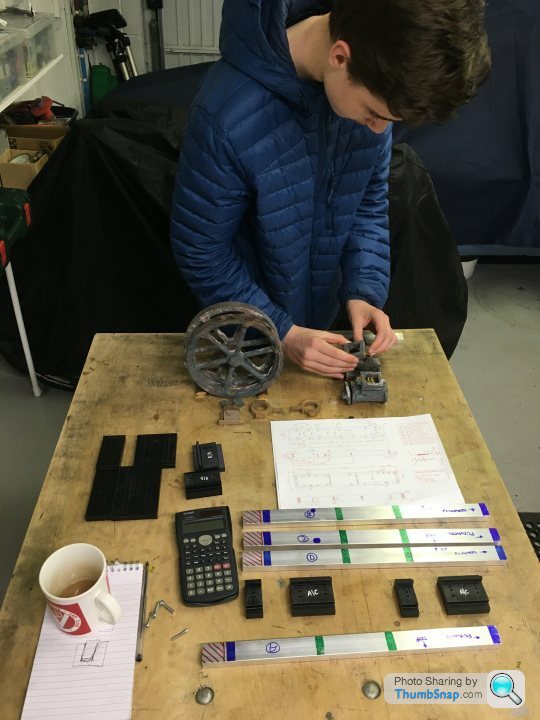
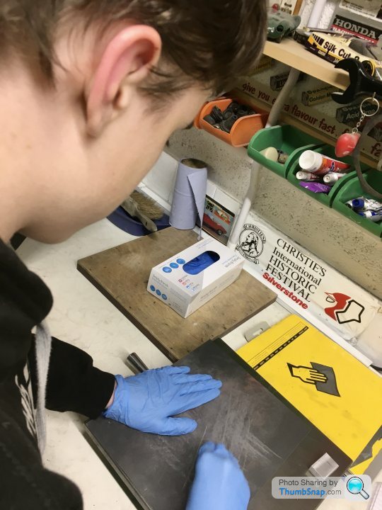
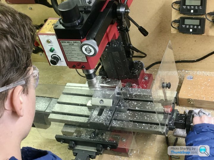
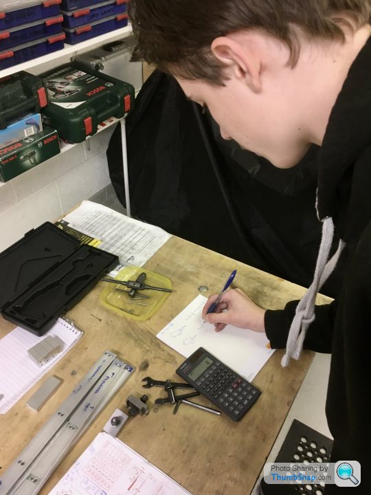
My excuse is that as well as figuring out how to do things myself, I’m then explaining what I’m thinking to my 13 y/o son, then showing him how to use measuring equipment and operate machine tools from pretty much scratch. He’s keen to try to do everything himself (for now!), and it’s nice to work together on something, but it’s inevitably a much slower process. I’m also wary of contradicting what he’s being taught in GCSE engineering...anyway, it is what it is.So this evening’s job was machining the middle bed spacers to thickness:

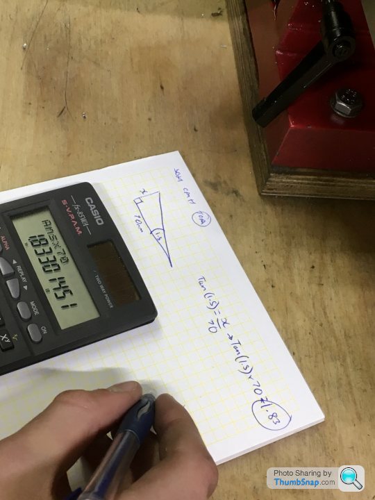
Then machining on the simulated casting draw taper. This was a good opportunity for the boy to apply the trigonometry He’s only just done in maths at school. No problem at all - measured the hypotenuse:
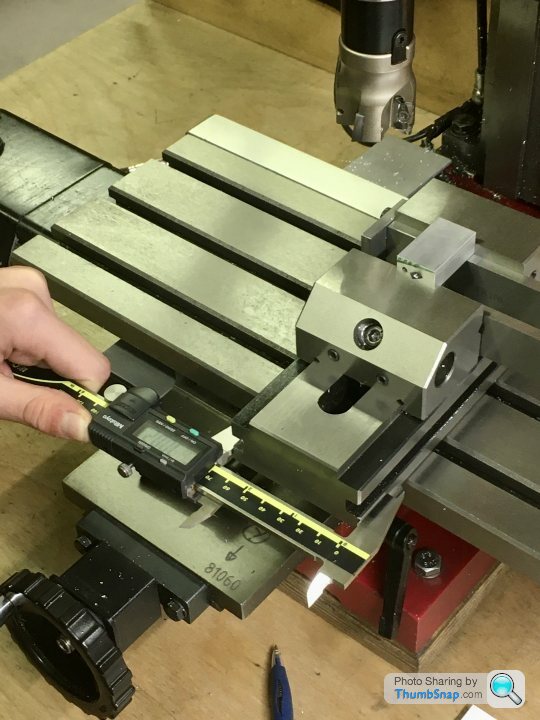
And worked out the depth of spacer needed to tilt the vice at 1.5 degrees. Good example of using trig, good timing too.
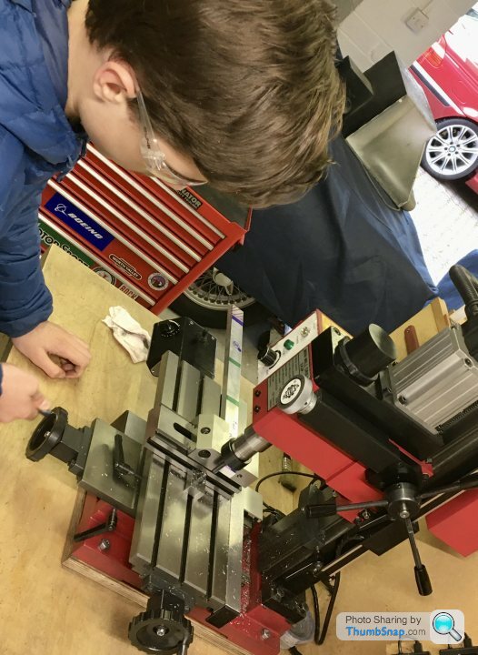
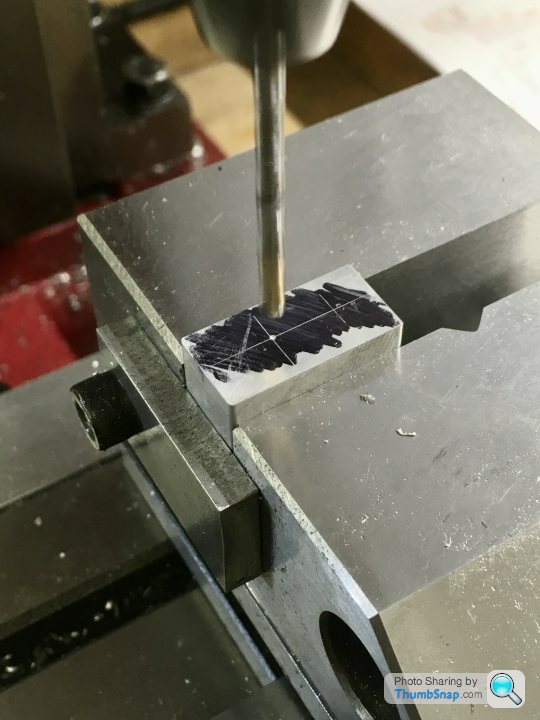
So we found some scrap, raised the vice and cut the first sides:
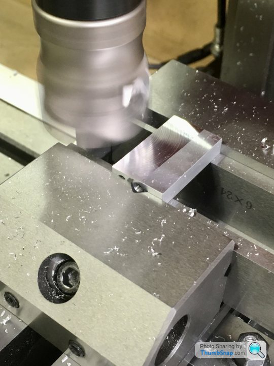
Then came the confusion. My assumption was that to get a symmetrical 3 degree taper on the blocks, all we had to do was machine 1.5 degrees on one face, flip it in the vice and machine the other face. I’d assumed that the 1.5 degree face would add to the 1.5 degree vice tilt, giving an overall 3 degrees. When I told him to do this he was having none of it; said it would either give zero degrees, or an asymmetric taper, and that we needed a 3 degree tilt for the second cut. Somewhat taken aback, I decided to prove my point with 2D CAD. Turns out he was right I think.
So we put one of the 3D printed 3 degree wedges I’d made for the long sides under the vice:
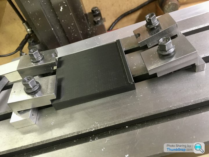
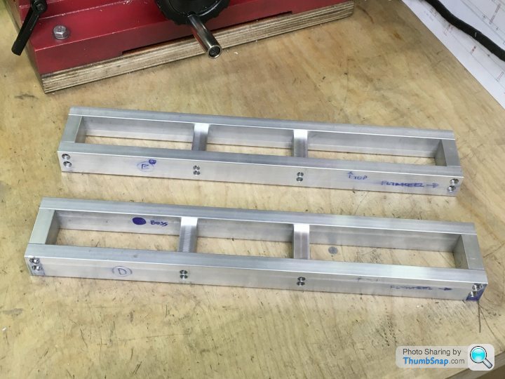
And cut the faces:
And they turned out spot-on:
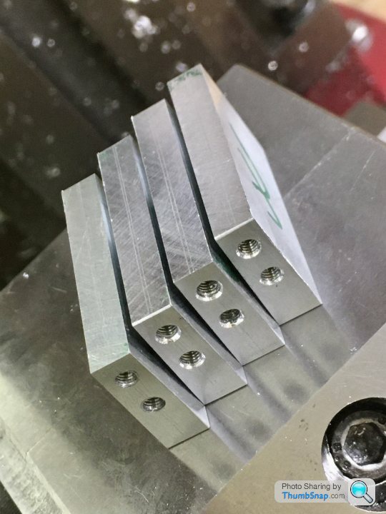
They just need rounds filing on the top edges.
So I suppose the moral is, don’t assume your student necessarily knows less than you.
Then machining on the simulated casting draw taper. This was a good opportunity for the boy to apply the trigonometry He’s only just done in maths at school. No problem at all - measured the hypotenuse:
And worked out the depth of spacer needed to tilt the vice at 1.5 degrees. Good example of using trig, good timing too.
So we found some scrap, raised the vice and cut the first sides:
Then came the confusion. My assumption was that to get a symmetrical 3 degree taper on the blocks, all we had to do was machine 1.5 degrees on one face, flip it in the vice and machine the other face. I’d assumed that the 1.5 degree face would add to the 1.5 degree vice tilt, giving an overall 3 degrees. When I told him to do this he was having none of it; said it would either give zero degrees, or an asymmetric taper, and that we needed a 3 degree tilt for the second cut. Somewhat taken aback, I decided to prove my point with 2D CAD. Turns out he was right I think.
So we put one of the 3D printed 3 degree wedges I’d made for the long sides under the vice:
And cut the faces:
And they turned out spot-on:
They just need rounds filing on the top edges.
So I suppose the moral is, don’t assume your student necessarily knows less than you.
Gassing Station | Scale Models | Top of Page | What's New | My Stuff