Stuart Twin Victoria (Princess Royal) Mill Engine
Discussion


Finished the Milliputing of the radii, flatting the excess and feathering off any rough edges, then abraded all over with Scotchbrite:

Immediately after Scotchbriting, sprayed with etch primer, and then skimmed the mating faces back to bare metal with #800 wet and dry:

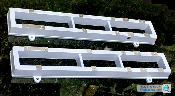

A few bits need some very minor further filling, but they can wait I until final painting on completion.
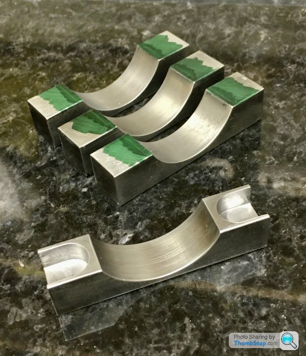
They’ve taken a lot longer than I thought to make, but I’ve learned some stuff on the way and overall I’m very happy with them. IMO they look much more refined than the Stuart originals - with the plinth around the bases, the throttle bell crank boss, and the top pads are now specific for the modified Princess Royal components. I suppose you could argue that the surface finish is too good for a casting, then again the bed for the 10V is very smooth, and I spent some time flatting that a bit before painting.
Next job: cylinder feet I think.
Immediately after Scotchbriting, sprayed with etch primer, and then skimmed the mating faces back to bare metal with #800 wet and dry:
A few bits need some very minor further filling, but they can wait I until final painting on completion.
They’ve taken a lot longer than I thought to make, but I’ve learned some stuff on the way and overall I’m very happy with them. IMO they look much more refined than the Stuart originals - with the plinth around the bases, the throttle bell crank boss, and the top pads are now specific for the modified Princess Royal components. I suppose you could argue that the surface finish is too good for a casting, then again the bed for the 10V is very smooth, and I spent some time flatting that a bit before painting.
Next job: cylinder feet I think.
So on to the cylinders - I wanted to clean them up to get an idea of the diameter to machine into the modified feet blocks.
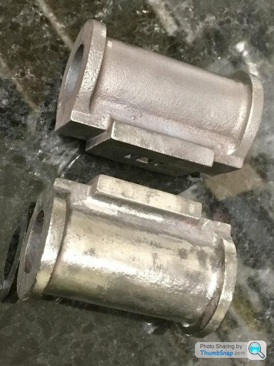
I actually have three - one was damaged when I got it; looked like whatever was used to separate it from its runner might have cut into the valve face:

There isn’t much machining allowance on there, so I sent a photo to Stuart Models who immediately sent another (excellent service). The intention is to use the damaged one for a machining test run, so I bodged some JB Weld into the cuts:

I cleaned the other two up, initially with a wire brush:

and removed the drain cock pads with a file, in preparation for fitting the feet:
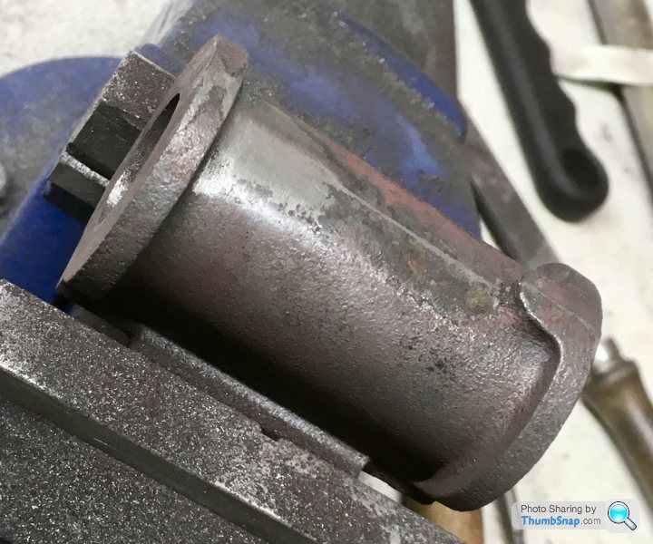
But then I noticed quite a bit of scaling on the surface, which wouldn’t come off:

The file just skated off it, so I resorted to a grinding bit in the Dremel:

Which seemed to do the trick, but there’s still a lot to remove. It’s worse on one casting than the other two. I wonder if putting them in the fire made it worse. I’m thinking of trying to remove it from the cylinder bore as well, before machining. I now understand What all the fuss is about regarding casting skins, and them ruining tools. There was none on the 10V.
Also began poking the steam ports with wire to remove any residual mould sand - again, one was much worse than the other:

So current status is two are about 50% fettled, still waiting for the JB weld to set on the other:
BTW the nominal diameter seems to be about 33.5mm, so I’ll machine the feet to 34 and hope for the best; the JB Weld should make up the rest.
I actually have three - one was damaged when I got it; looked like whatever was used to separate it from its runner might have cut into the valve face:
There isn’t much machining allowance on there, so I sent a photo to Stuart Models who immediately sent another (excellent service). The intention is to use the damaged one for a machining test run, so I bodged some JB Weld into the cuts:
I cleaned the other two up, initially with a wire brush:
and removed the drain cock pads with a file, in preparation for fitting the feet:
But then I noticed quite a bit of scaling on the surface, which wouldn’t come off:
The file just skated off it, so I resorted to a grinding bit in the Dremel:
Which seemed to do the trick, but there’s still a lot to remove. It’s worse on one casting than the other two. I wonder if putting them in the fire made it worse. I’m thinking of trying to remove it from the cylinder bore as well, before machining. I now understand What all the fuss is about regarding casting skins, and them ruining tools. There was none on the 10V.
Also began poking the steam ports with wire to remove any residual mould sand - again, one was much worse than the other:
So current status is two are about 50% fettled, still waiting for the JB weld to set on the other:
BTW the nominal diameter seems to be about 33.5mm, so I’ll machine the feet to 34 and hope for the best; the JB Weld should make up the rest.
Made some centre plugs for the cylinders,
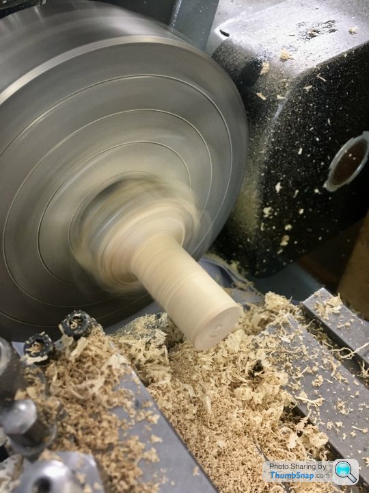
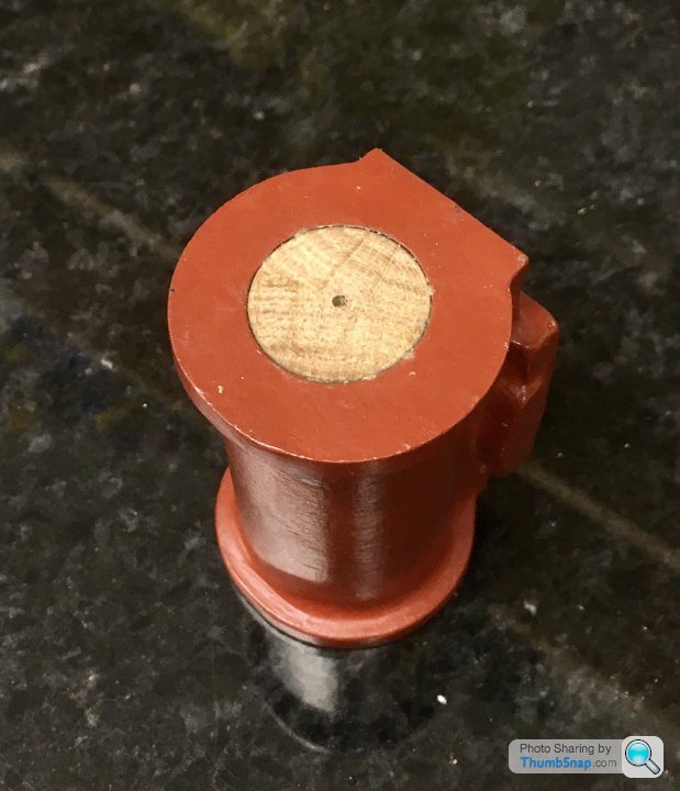
and checked them using the arc method, scribing a circle with dividers and going round with the odd leg callipers:
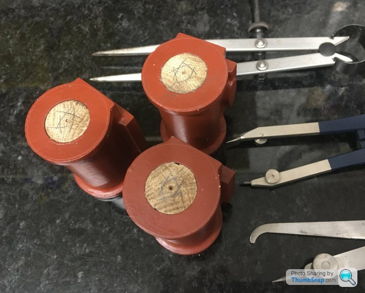
Most are pretty good, might re-do a couple, although they might be ok, but a bit oval.
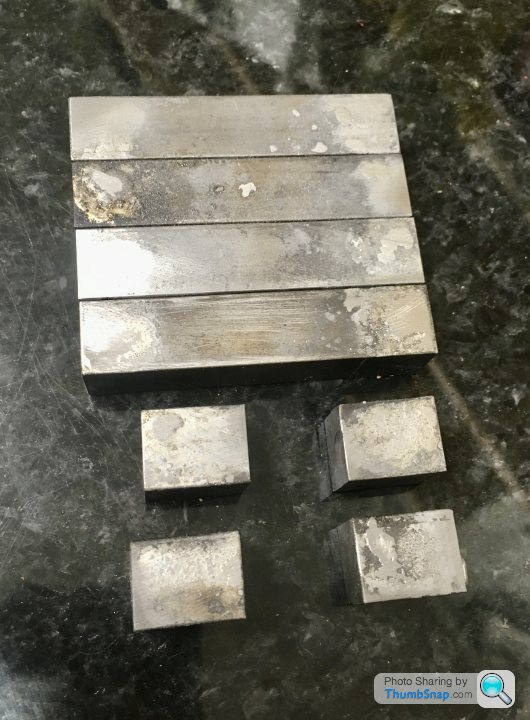
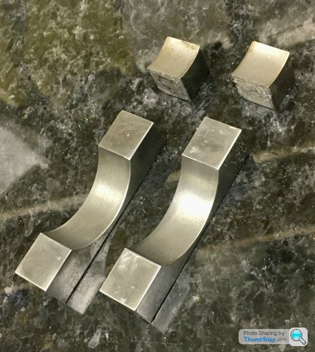
Also divided the 1/2” square bar up for the feet. Just enough in the end, using short middle bits:
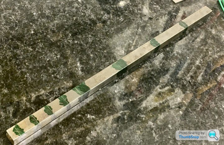
I milled them to consistent lengths, and they are a bit oversized so I can trim them once fitted:

Didn’t have much luck soldering them together, the solder only seemed to capillary into a tiny bit of the cleaned and fluxed joints. I tried to tin the mating faces, but they weren’t having any of it…a slight tap saw them fall apart…
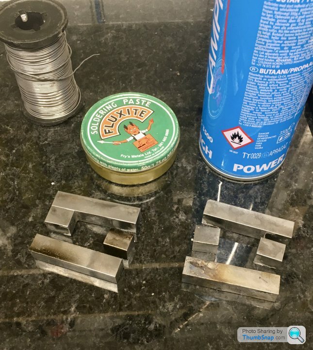
Perhaps the wrong flux, or not enough heat (propane/butane mix?
Anyway some progress at least.
and checked them using the arc method, scribing a circle with dividers and going round with the odd leg callipers:
Most are pretty good, might re-do a couple, although they might be ok, but a bit oval.
Also divided the 1/2” square bar up for the feet. Just enough in the end, using short middle bits:
I milled them to consistent lengths, and they are a bit oversized so I can trim them once fitted:
Didn’t have much luck soldering them together, the solder only seemed to capillary into a tiny bit of the cleaned and fluxed joints. I tried to tin the mating faces, but they weren’t having any of it…a slight tap saw them fall apart…
Perhaps the wrong flux, or not enough heat (propane/butane mix?
Anyway some progress at least.
Soft soldering part 2. I considered using Space Shuttle heat shield insulation to rest the parts on (to retain heat within the parts). I’ve had it for years and it’s pretty useless:
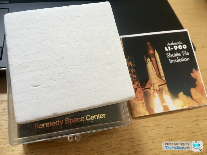
Then looked at how much it goes for on EBay and thought again (apparently production of it ceased in 1993). Settled on pre-tinning each individual part held in air on a stand:

Which worked:
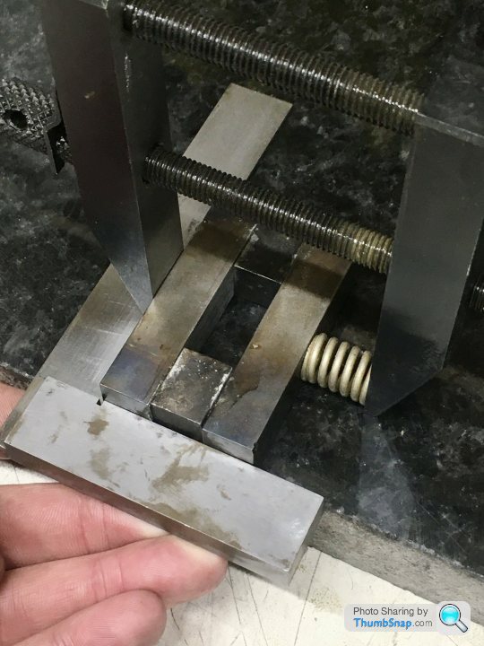
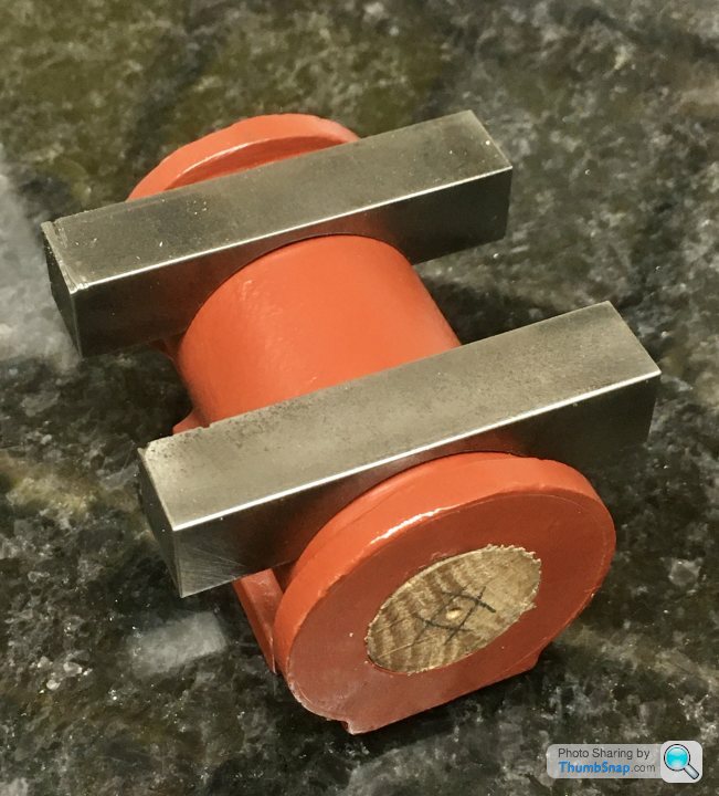
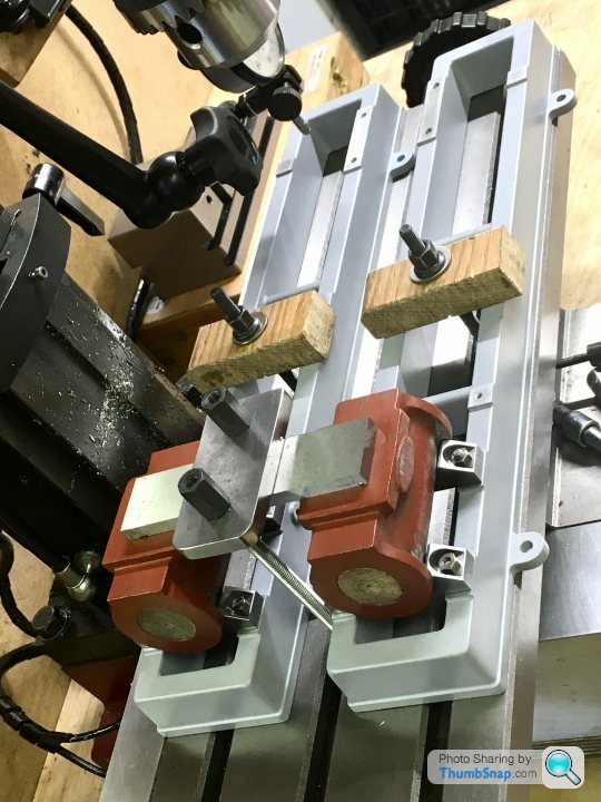
Then needed to clamp the parts to solder them all together. If a normal clamp was used, when the solder melts, the whole thing would drop out of position. I spring-loaded the assembly to prevent this:
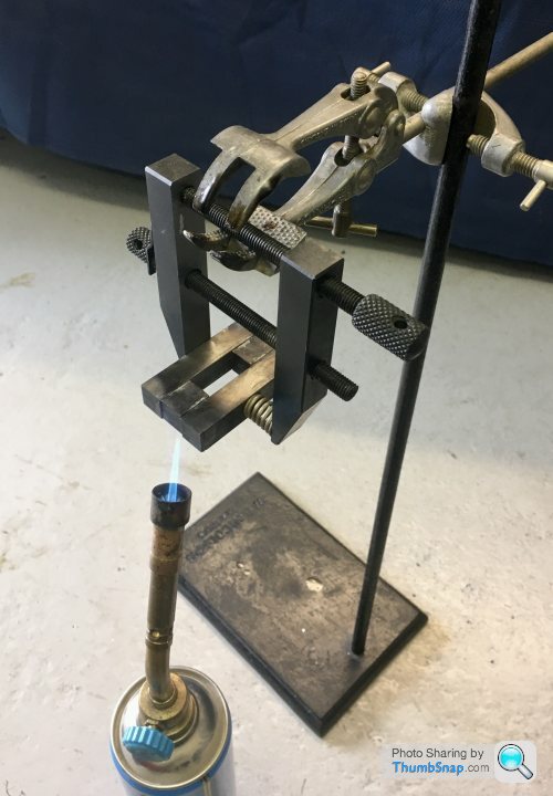
Then hung on the stand and sweated it all together:
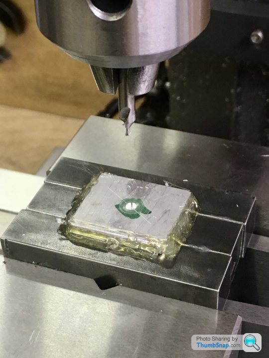
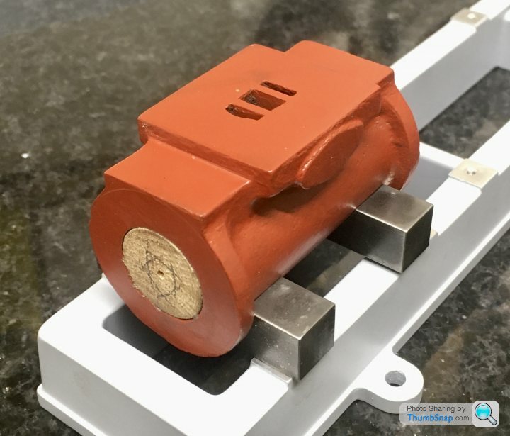
Initially used wood marked with diagonals to get the centre, but checking with dividers gave an offset, which I didn’t want:

so used hot melt glue to put a piece of aluminium in the middle, and drilled the centre using the DROs in the mill. Then it was spot-on:
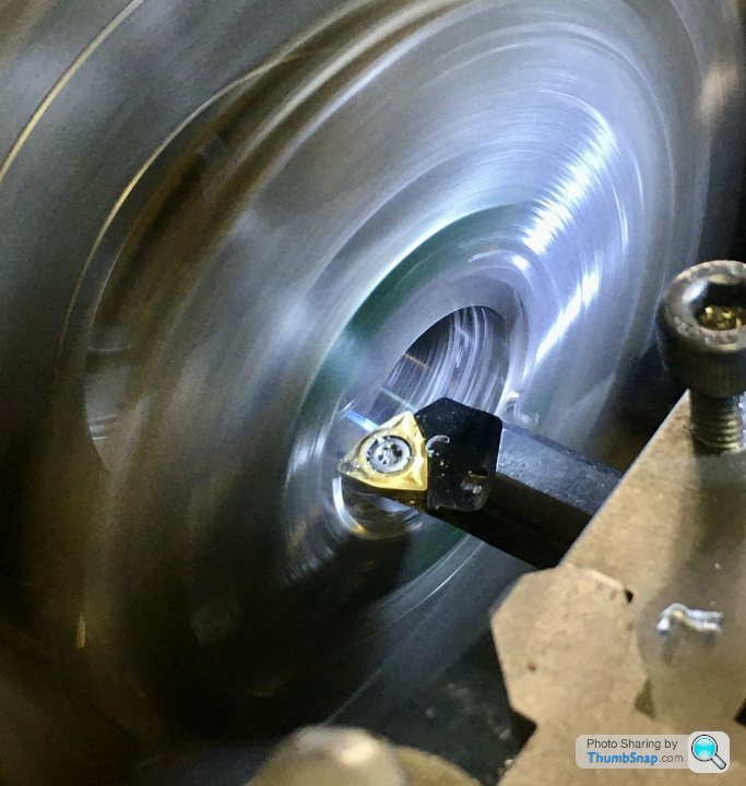
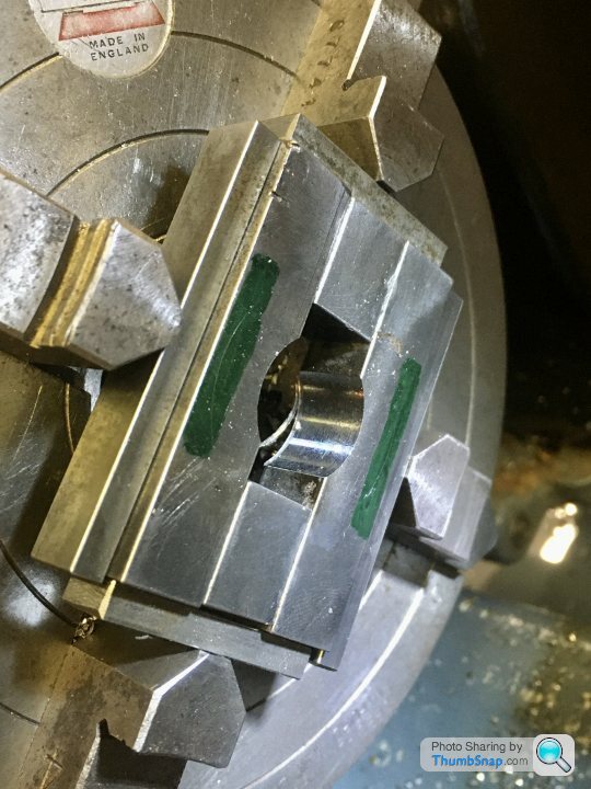
Then centred in the 4-jaw Chuck using spreader plates:

And gradually opened up to size. The initial cuts were very rough for some reason, almost as if the surface was hardened by the sweating/cooling process. After the third or fourth 0.0025” cut, it became smooth.
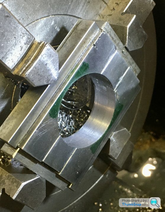
Then un-soldered again:
Seems a good fit for the first one. I suppose I could have turned a chamfer on one side rather than filing it to mate it to the cylinder flanges, but whatever:
Still quite a bit to do, but so far so good this evening.
Then looked at how much it goes for on EBay and thought again (apparently production of it ceased in 1993). Settled on pre-tinning each individual part held in air on a stand:
Which worked:
Then needed to clamp the parts to solder them all together. If a normal clamp was used, when the solder melts, the whole thing would drop out of position. I spring-loaded the assembly to prevent this:
Then hung on the stand and sweated it all together:
Initially used wood marked with diagonals to get the centre, but checking with dividers gave an offset, which I didn’t want:
so used hot melt glue to put a piece of aluminium in the middle, and drilled the centre using the DROs in the mill. Then it was spot-on:
Then centred in the 4-jaw Chuck using spreader plates:
And gradually opened up to size. The initial cuts were very rough for some reason, almost as if the surface was hardened by the sweating/cooling process. After the third or fourth 0.0025” cut, it became smooth.
Then un-soldered again:
Seems a good fit for the first one. I suppose I could have turned a chamfer on one side rather than filing it to mate it to the cylinder flanges, but whatever:
Still quite a bit to do, but so far so good this evening.
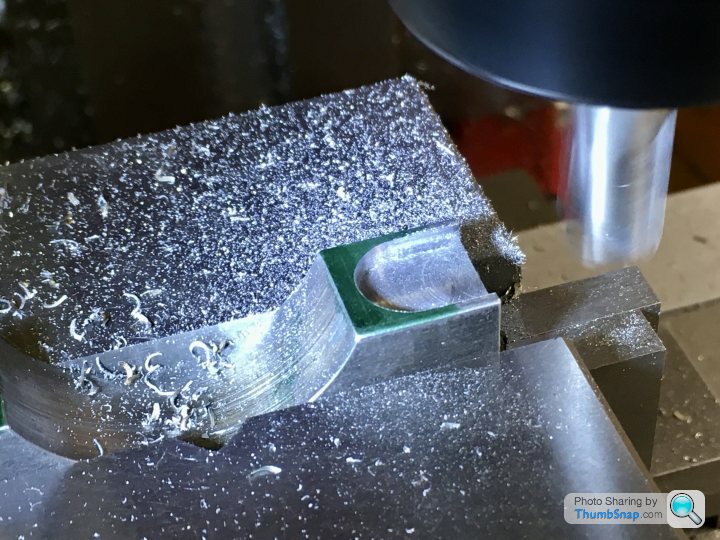
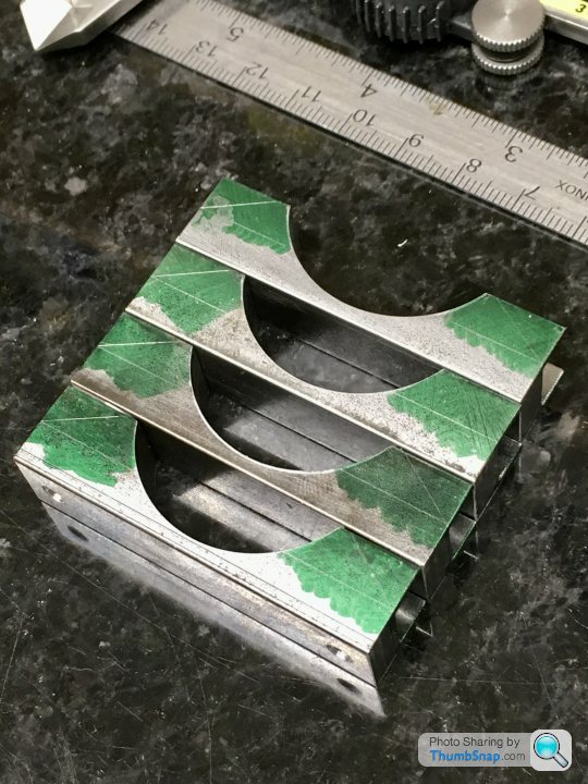
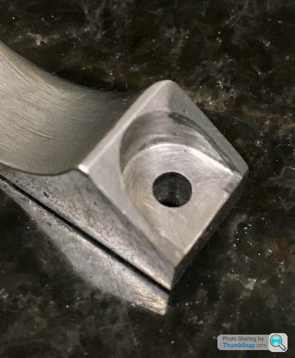
Carried on machining the other two feet, which was straightforward, then marked out for the pockets, which I did with a slot drill. I marked the extents of the rads w.r.t. the edges of the arc cut-out:
After cutting both pockets I double-checked the centres with the DRO, and they matched the base hole centres, so as per the drawings/instructions:
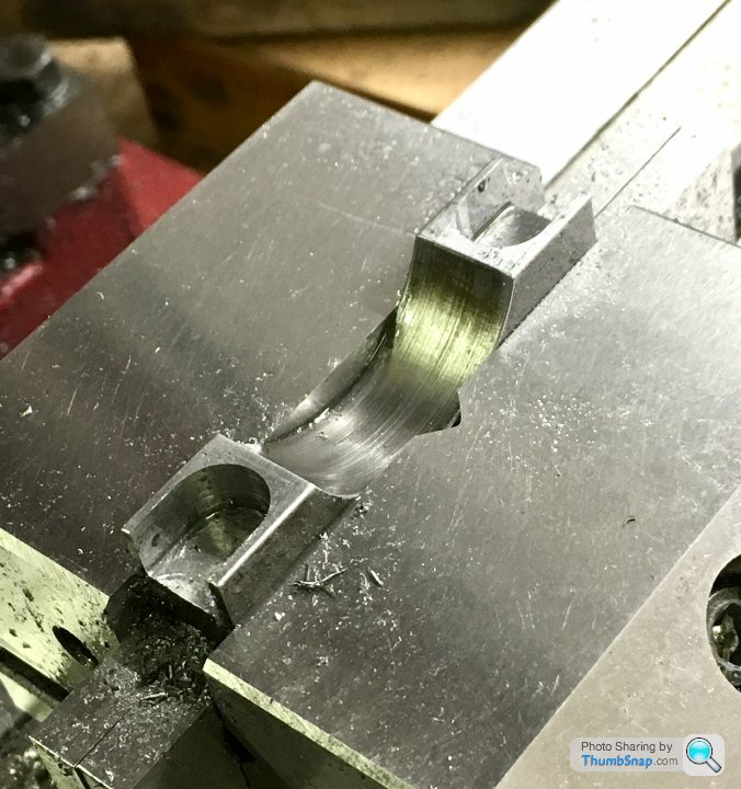
The result (still needs the flanks chamfering):
The question is (there’s always a question!):
The base holes are spaced at 44.46 mm, the pocket centres in the feet are the same. So, unless the feet are attached to the cylinder castings precisely such that the finished axis ends up dead in the middle (seems unlikely), then the feet hole centres will not match the pocket centres. There will be some lateral mismatch. I checked a 4BA hexagon, and it gives about 2mm gap on radius between the points and the pocket…I can’t bring the pockets any further in toward the castings otherwise they’ll break into the cut-out arc (the edges need still need filing slightly for a snug fit).
I think I’ll have to figure out some method of placing the un-bored cylinders onto the properly spaced feet before fixing them (ie using the centred wooden plugs).
After cutting both pockets I double-checked the centres with the DRO, and they matched the base hole centres, so as per the drawings/instructions:
The result (still needs the flanks chamfering):
The question is (there’s always a question!):
The base holes are spaced at 44.46 mm, the pocket centres in the feet are the same. So, unless the feet are attached to the cylinder castings precisely such that the finished axis ends up dead in the middle (seems unlikely), then the feet hole centres will not match the pocket centres. There will be some lateral mismatch. I checked a 4BA hexagon, and it gives about 2mm gap on radius between the points and the pocket…I can’t bring the pockets any further in toward the castings otherwise they’ll break into the cut-out arc (the edges need still need filing slightly for a snug fit).
I think I’ll have to figure out some method of placing the un-bored cylinders onto the properly spaced feet before fixing them (ie using the centred wooden plugs).
So I machined the slots in the rest of the feet and drilled the mounting holes to be a close fit on the screws. Eventually I’ll open them up to 4mm as per the instructions, to give some wiggle room to adjust on assembly to the beds:
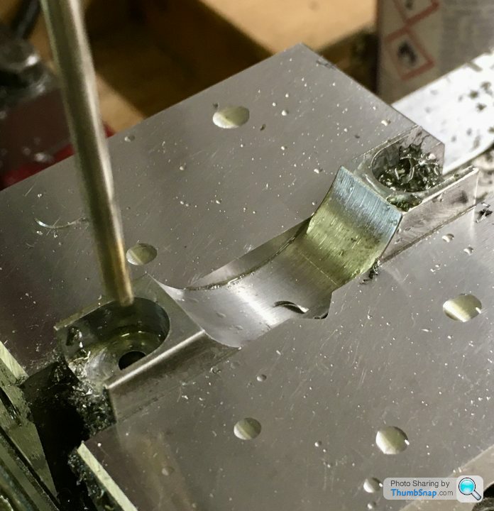
Then, using the holes as datums, trimmed the feet to length, plus a fraction so I can finally machine them once the cylinders are bored:
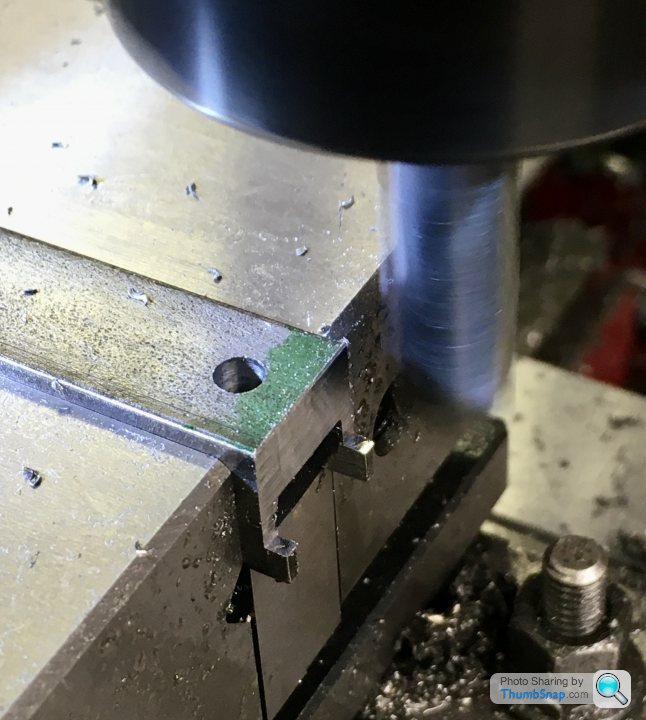
Then marked out for cutting the chamfers:

It says in the article to file these, but it was easy enough to do them in the mill…or so I thought.
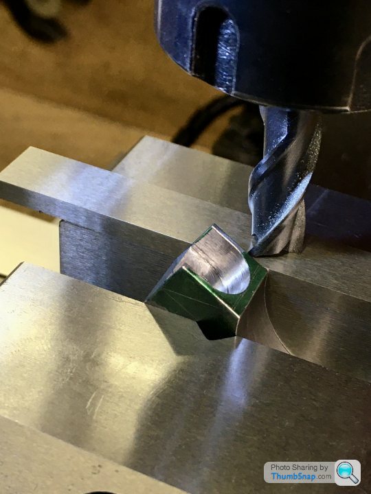

…but of course, one slight grab with this mill, and all the careful work is undone:

I really need to get a better machine. I know…bad workman and all that, but jeez. Anyway, here they are:

Test fitted:

Then started on grinding and filing a chamfer on one side of each foot, to clear the radius on the cylinders:

And abraded the castings to suit, ready for bonding:
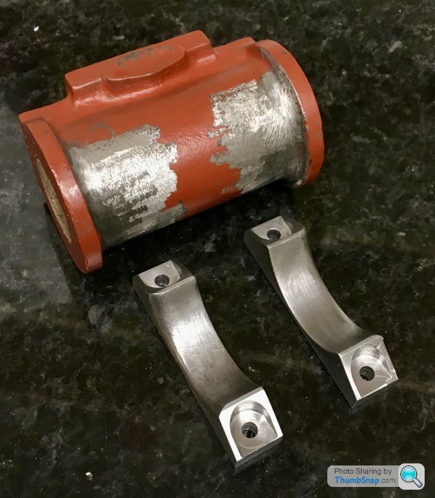
They seem to fit well enough:


A very basic height check seems to indicate all is well there:

So that’s today’s progress:

I’ve re-thought the next stage: I’m going to re-fit the bases to the mill bed, align them perfectly, then use them as jigs in conjunction with the DROs and a pointer in the chuck to check the cylinder centre heights, longitudinal alignment and valve face height/level during the JB Welding process. This should get me well within 1mm of alignment once everything is set and bored. Of course final machining of the foot widths, feet pad undersides, valve face and cylinder ends will be done after boring, with the cylinder axis as the datum.
So what to do about the damaged foot? I put JB Weld on a damaged corner of a valve face, and it chipped straight off during filing. Could soft solder a piece on, and re-machine? Could try Milliput? Or buy more steel and start again?
Overall happy so far, considering the stuff I’ve machined is more cosmetic than needing ultimate accuracy…but that mill is driving me mad.
Then, using the holes as datums, trimmed the feet to length, plus a fraction so I can finally machine them once the cylinders are bored:
Then marked out for cutting the chamfers:
It says in the article to file these, but it was easy enough to do them in the mill…or so I thought.
…but of course, one slight grab with this mill, and all the careful work is undone:
I really need to get a better machine. I know…bad workman and all that, but jeez. Anyway, here they are:
Test fitted:
Then started on grinding and filing a chamfer on one side of each foot, to clear the radius on the cylinders:
And abraded the castings to suit, ready for bonding:
They seem to fit well enough:
A very basic height check seems to indicate all is well there:
So that’s today’s progress:
I’ve re-thought the next stage: I’m going to re-fit the bases to the mill bed, align them perfectly, then use them as jigs in conjunction with the DROs and a pointer in the chuck to check the cylinder centre heights, longitudinal alignment and valve face height/level during the JB Welding process. This should get me well within 1mm of alignment once everything is set and bored. Of course final machining of the foot widths, feet pad undersides, valve face and cylinder ends will be done after boring, with the cylinder axis as the datum.
So what to do about the damaged foot? I put JB Weld on a damaged corner of a valve face, and it chipped straight off during filing. Could soft solder a piece on, and re-machine? Could try Milliput? Or buy more steel and start again?
Overall happy so far, considering the stuff I’ve machined is more cosmetic than needing ultimate accuracy…but that mill is driving me mad.
looking good on the progress to date. For my tuppence worth regarding the foot grab damage, I would suggest some careful brazing on the foot to build it up, or as you have your soldering process worked out, build it up with that and file to size. It's just going to be cosmetic and probably painted over anyway. However if the OCD gets the better of you, then starting from scratch is the only way to sleep at nights! You might be able to set up the square section shimmed to the right height on your lathe crossslide and lock it in place, then use a boring head in the lathe spindle to cut the profile on just the one piece. You can slowly index out the boring bar to the final radius to keep from taking too heavy a cut. For that radius I think you should have enough height from the cross slide to the lathe centre line. I suggest this only due to your comments on the present milling machine, which is basically just a vertically orientated lathe.
rolster said:
looking good on the progress to date. For my tuppence worth regarding the foot grab damage, I would suggest some careful brazing on the foot to build it up, or as you have your soldering process worked out, build it up with that and file to size. It's just going to be cosmetic and probably painted over anyway. However if the OCD gets the better of you, then starting from scratch is the only way to sleep at nights! You might be able to set up the square section shimmed to the right height on your lathe crossslide and lock it in place, then use a boring head in the lathe spindle to cut the profile on just the one piece. You can slowly index out the boring bar to the final radius to keep from taking too heavy a cut. For that radius I think you should have enough height from the cross slide to the lathe centre line. I suggest this only due to your comments on the present milling machine, which is basically just a vertically orientated lathe.
Thanks Rolster.After some advice over on the ME forum, I've ended up JB Welding the damage, and will fully machine it back to size on the mill when it's fully cured. As you say, it's 100% cosmetic, and as with the beds, the interfaces with the cylinders will be Milliputted and then rolled over with a ball tool to give a simulated cast fillet.
I was kind of skeptical about making simulated castings and whether they we're "real" model engineering, or a bodge, but the experts over on ME (who produce some jaw-droppingly fine work), seem to use the technique routinely in order to avoid making or buying castings. Again, mainly on parts or areas that will never be subject to any great stress or critical tolerances. If it's good enough for them, it's fine by me.
The mill I have is really I guess a glorified drilling machine - the z-axis is a rack and pinion, and the backlash isn't even funny. A z-ballscrew would be a good modification, but I bought the mill to make parts, not to modify it. If I could find an equivalent used "proper" mill for less than £1k I'd probably have a go at it at some point.
Great to hear you have a plan set on the foot repair. In regards to a milling machine just keep a good eye on the machine tool clearance websites. Unfortunately the prior generations of model engineers are dropping away and their families have no interest, so put up all the tooling for sale. There can be some good machines had at a reasonable price. However the dealers are a Buisness and have to make money as well! Keep up the good work and I am following your thread with interest. Of course I have an ulterior motive hoping you will finish the paper ship off once this is done🤭😁

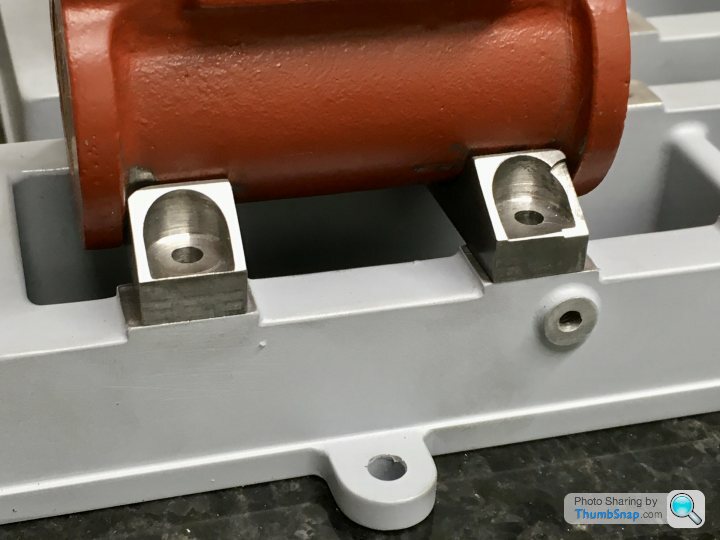
Set both beds up aligned to the mill base:
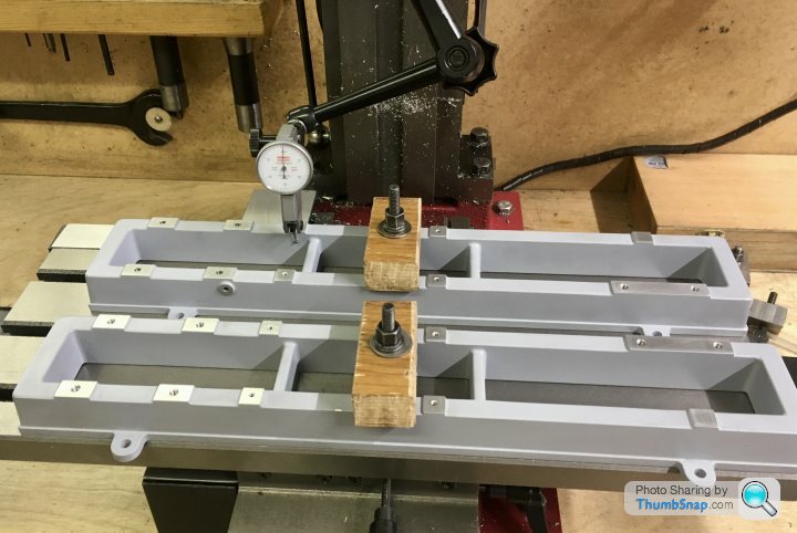
Checked for height of the pads:
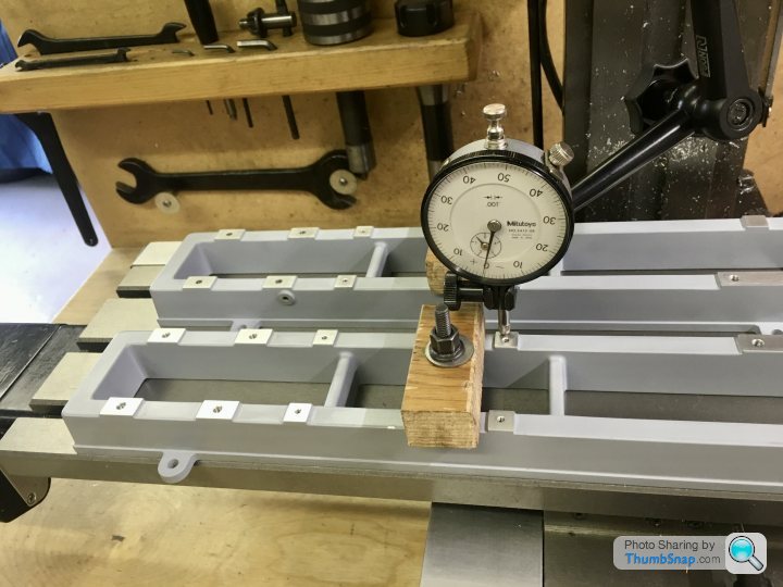
Then bolted the feet on:
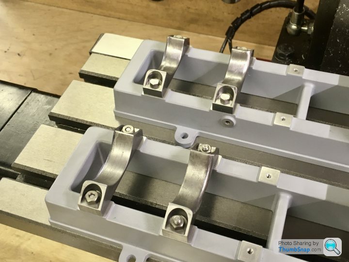
And placed the cylinders on the feet, with the valve faces clamped nominally flat with a parallel:
Idea is to use the mill as a primitive CMM, to check the positions of the cylinder centres and valve faces (edges and top faces) before bonding & bolting to the feet.
A quick visual check with a pointer indicated everything was OK. I’ll do some more accurate checks tomorrow on the valve faces, then get the JB Weld out again.
Checked for height of the pads:
Then bolted the feet on:
And placed the cylinders on the feet, with the valve faces clamped nominally flat with a parallel:
Idea is to use the mill as a primitive CMM, to check the positions of the cylinder centres and valve faces (edges and top faces) before bonding & bolting to the feet.
A quick visual check with a pointer indicated everything was OK. I’ll do some more accurate checks tomorrow on the valve faces, then get the JB Weld out again.
rolster said:
Great to hear you have a plan set on the foot repair. In regards to a milling machine just keep a good eye on the machine tool clearance websites. Unfortunately the prior generations of model engineers are dropping away and their families have no interest, so put up all the tooling for sale. There can be some good machines had at a reasonable price. However the dealers are a Buisness and have to make money as well! Keep up the good work and I am following your thread with interest. Of course I have an ulterior motive hoping you will finish the paper ship off once this is done????
I think you’re probably right about the younger generation not being as bothered about model engineering, and therefore not wanting the equipment. Then again, it doesn’t necessarily need to be younger people buying the stuff to make it scarce. I’m a beginner at 50, but am after exactly the same equipment as a beginner at 20. Namely good quality used machine tools of a small enough size for a garage - these will always command a premium over the larger machine shop items simply due to the space they take up. Also, when I joined the Model Engineer forum group last year just after lockdown, apparently the number of beginners posting questions was unprecedented. Whether they’ve all stuck at it or not I don’t know.BTW I’d forgotten about the Bismarck. That’s another project on the list to complete…
looking great and glad to see things are aligning fine. Before going to far with the JB weld perhaps consider the orientation of the steam exhaust bosses from the cylinders as it would probably work out neetly to have them both facing inwards to have a commom exhaust to a condenser or just out of the way. Not to worry on the age front i am just a few years older than you but have not had my own workshop for sixteen years now, however am working with architects now on a design for a new one in my garden here in France so i can ship my tooling from the U.K over here and use it again, my father enjoys it mixed in with his currently. I am a little lucky with my job, allowing me to keep my hand in when i am visiting shipyards and vessels around the planet. although a recent near 8 months in China did push the bounderies somewhat.
Gassing Station | Scale Models | Top of Page | What's New | My Stuff