Stuart Twin Victoria (Princess Royal) Mill Engine
Discussion


rolster said:
looking great and glad to see things are aligning fine. Before going to far with the JB weld perhaps consider the orientation of the steam exhaust bosses from the cylinders as it would probably work out neetly to have them both facing inwards to have a commom exhaust to a condenser or just out of the way. Not to worry on the age front i am just a few years older than you but have not had my own workshop for sixteen years now, however am working with architects now on a design for a new one in my garden here in France so i can ship my tooling from the U.K over here and use it again, my father enjoys it mixed in with his currently. I am a little lucky with my job, allowing me to keep my hand in when i am visiting shipyards and vessels around the planet. although a recent near 8 months in China did push the bounderies somewhat.
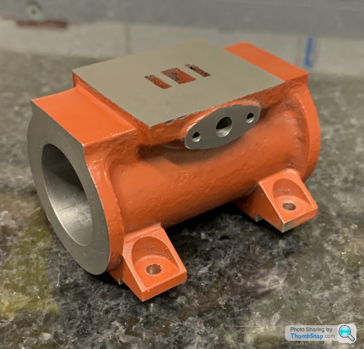
Thanks, yes. Sounds like your workshop will be great...I'm building to plan, so the exhausts are both outboard (I'd better check!). The inlets have to be on the insides because that's where the throttle linkages from the governor are. I think the exhaust pipes would interfere with them if on the inside as well.
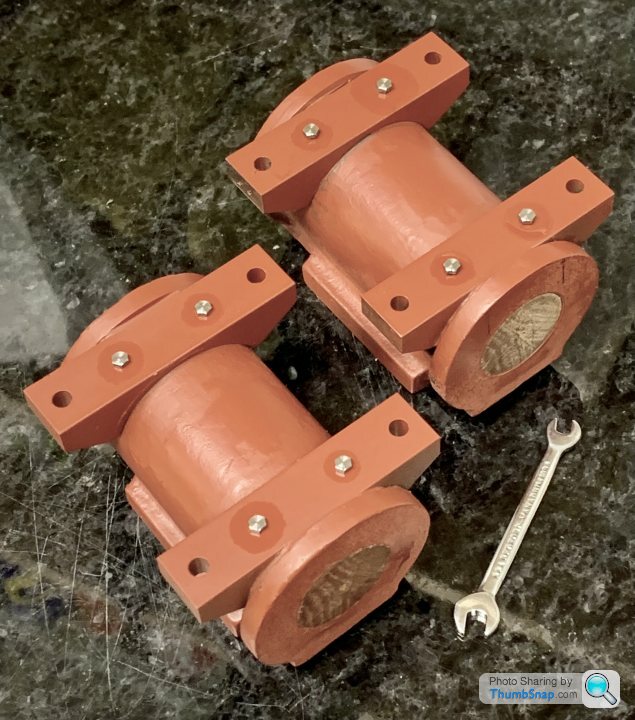
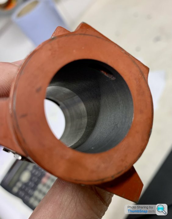
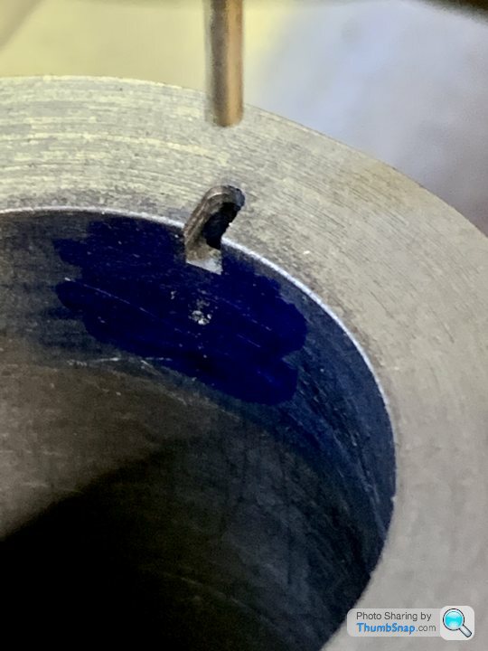
Double-checked the centres of the bores w.r.t the flanges, and I doubt I can get them better as a ‘best fit’. Also checked the valve face edges - again not bad. Then degreased the mating faces and on with the JB Weld:
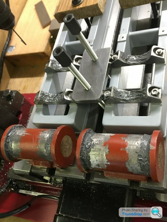
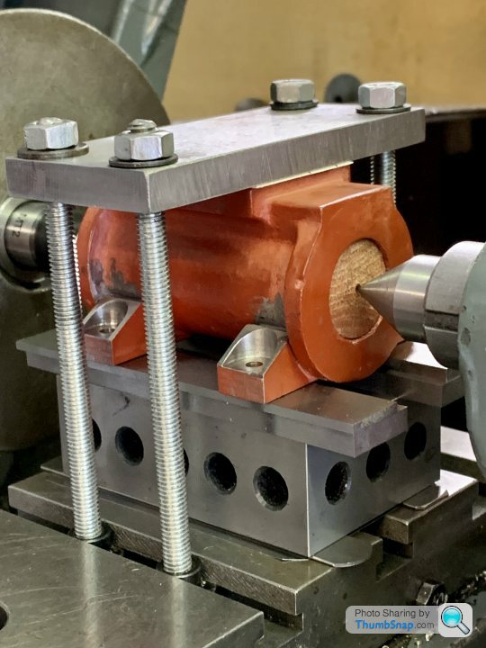
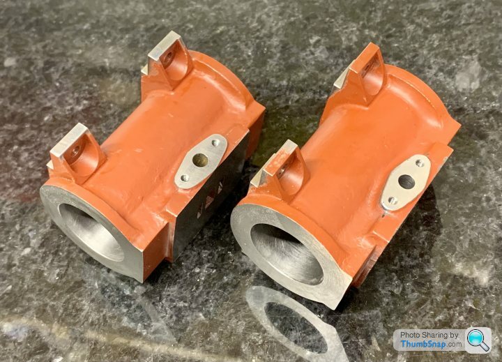
Then a final check everything had gone back in place correctly, then clamped down
and scraped off all the excess that squeezed out. I’ll leave them now for 48 hours, then drill and tap for the bolts:
I keep forgetting I can re-align for best-fit on the faces and feet after boring, but the closer it is now the better I guess.
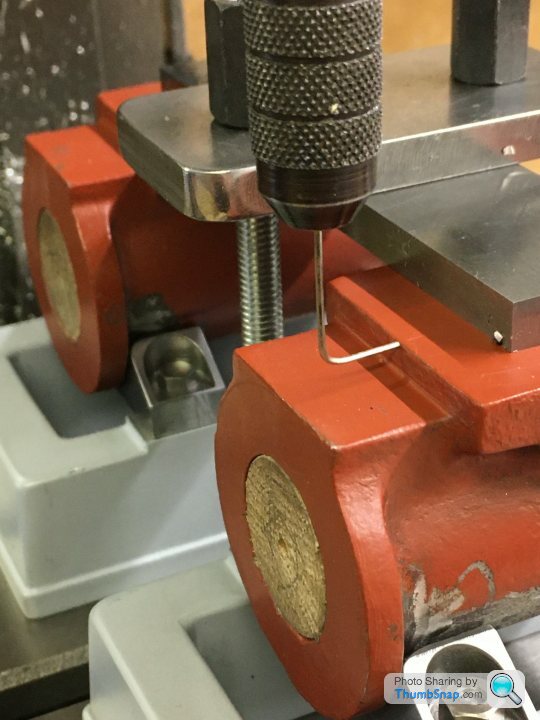
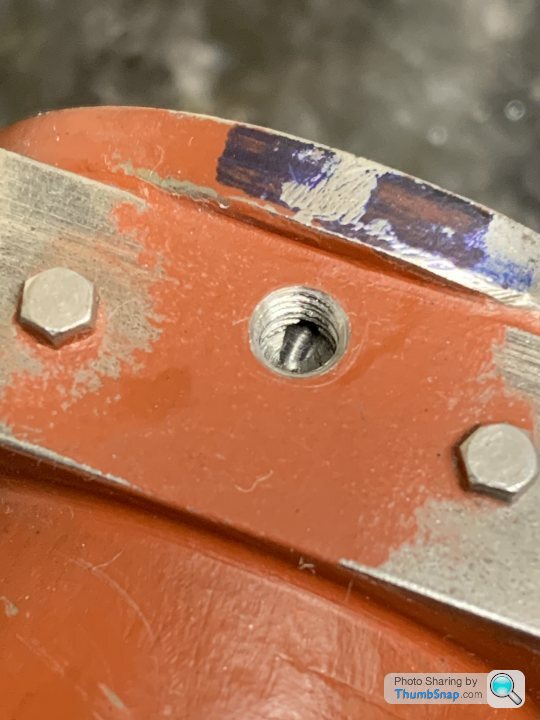
The 10BA bolts finally arrived, so I drilled and tapped the cylinder feet to suit:
I ground the tip off the tap to ensure the minimum hole depth. Time will tell if the holes will break into the cylinders…
They look pretty small for the job, but they are as per the instructions. TBH I think the JB Weld would have been fine on its own.
I’ll de-grease everything and fit the bolts permanently after coating with more JB Weld. Then it’s cylinder boring time.
allegerita said:
I understand from an earlier remark they are not supposed to go through so what is the function of these holes?
They are there just as a mechanical fixing for the feet. It says in the plans that breaking through into the cylinder is a bit hit-and-miss, but once machined and lapped, shouldn’t make any difference either way.There are also holes in the cylinders that lead to drain cocks, but I don’t think there are in the swept area of the cylinders.

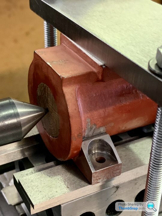
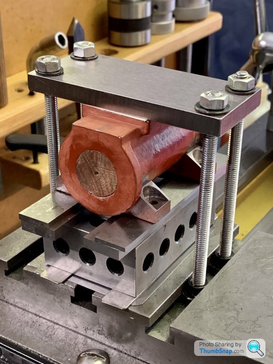
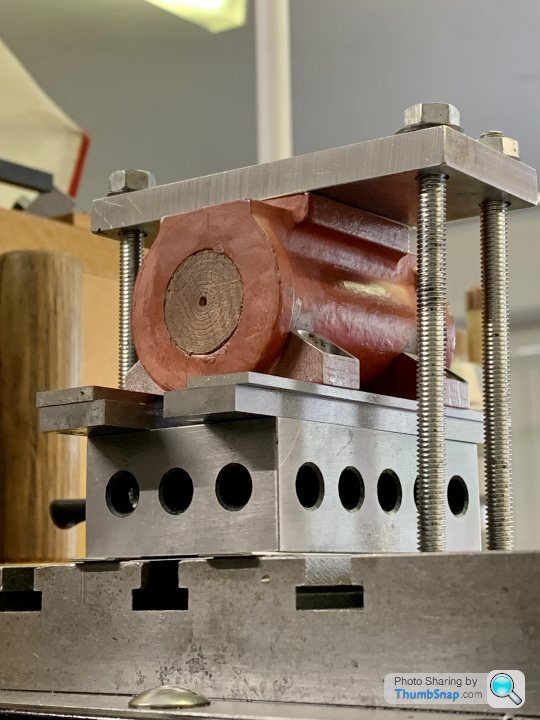
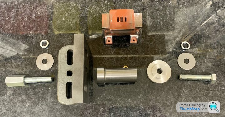
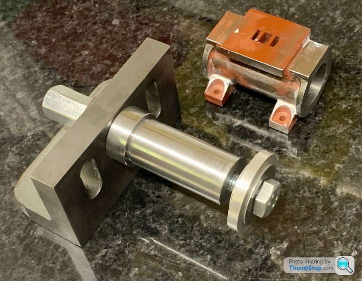
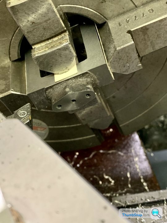
After some advice over on the ME forum, I changed the fixture to give more security:
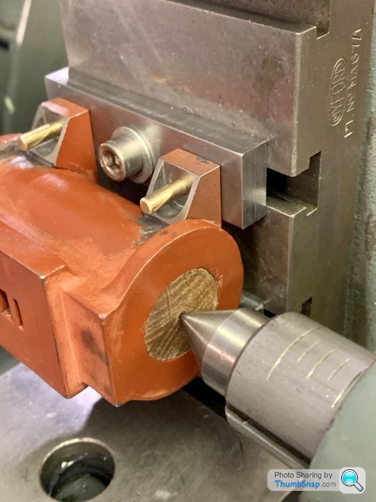
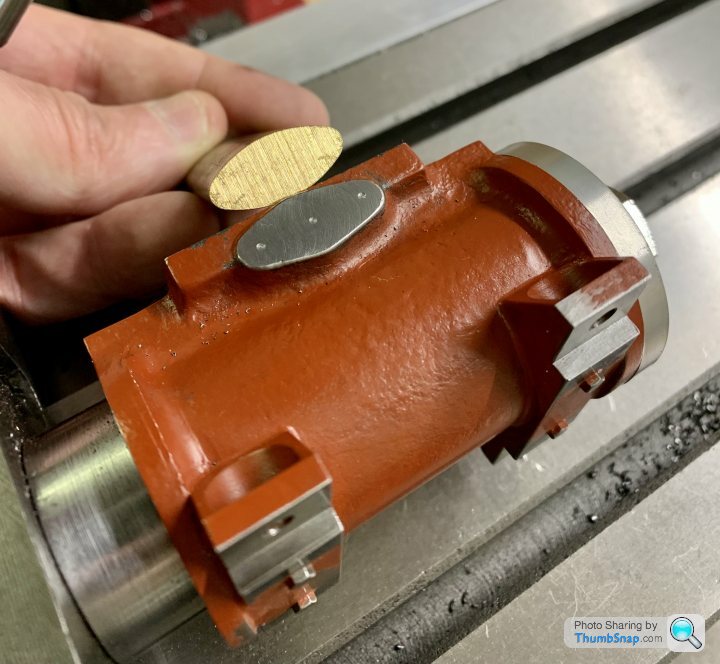
Made some brass pins to check alignment of the feet:
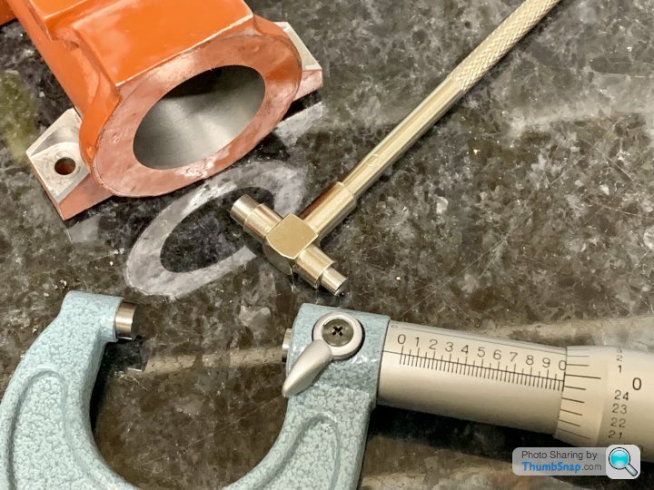
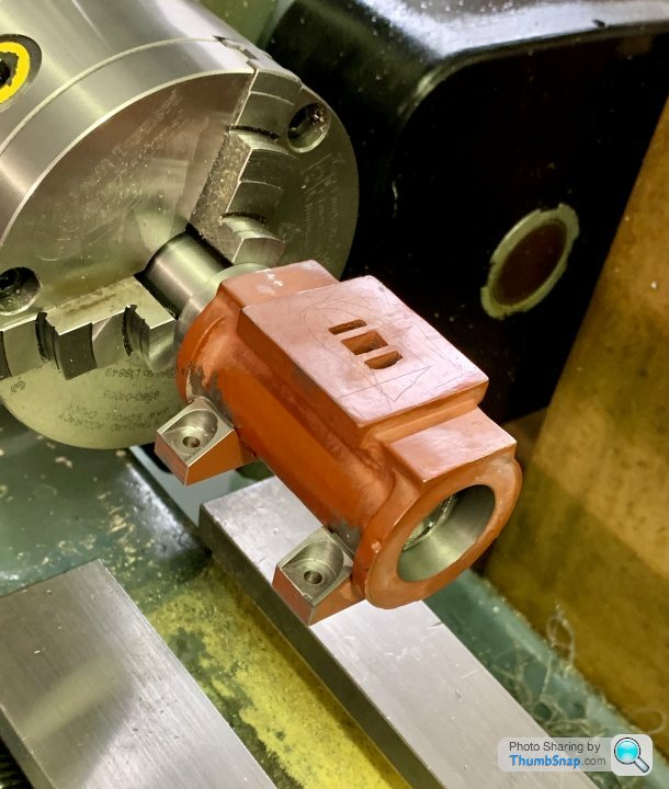
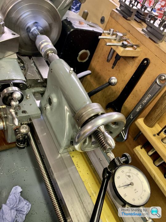
Then aligned the plug centres with the lathe centres:
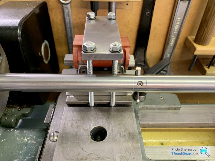
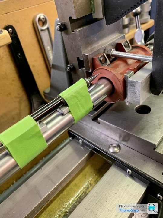
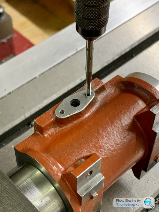
Then fitted the bar and taped a pencil to it to check concentricity with the cast flanges:
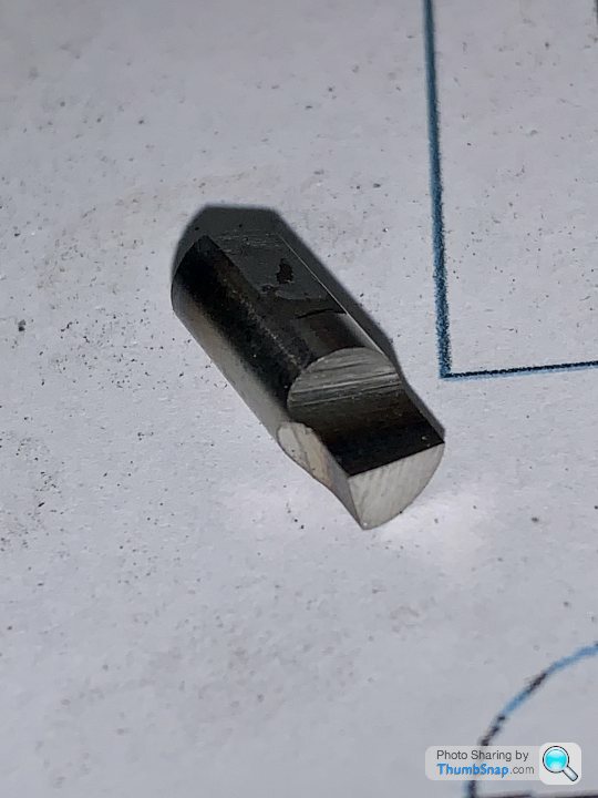
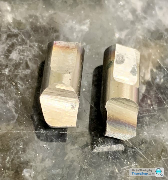
Then ground a tool bit:
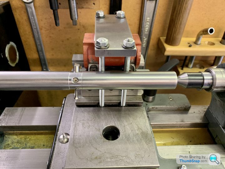
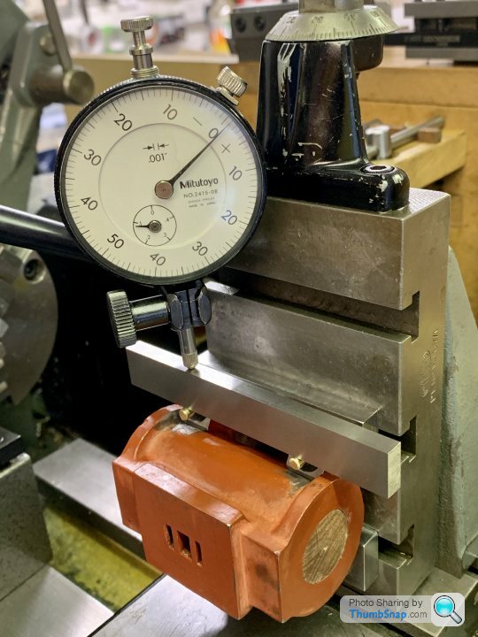
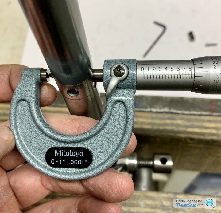
Set up with the micrometer as a baseline for subsequent adjustments:
Then bit the bullet and made a start:
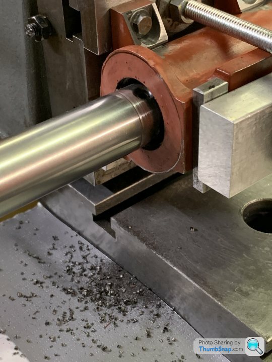
Seemed to go ok so for the final cuts made a radiussed bit to give a better surface finish:
After a bit of re-profiling, got a good result, and managed to increment the cuts up to size:

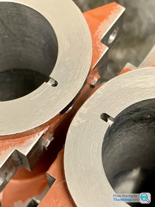
Cylindrical too, so I called it a result. There was a mystery discolouration half way along the bore; no ridge, and the same diameter all the way. A hard spot or inclusion slightly taking the edge off the tool was a suggested reason. Anyway, this effect should disappear with the super finishing later on:
Second cylinder no problem:
Next job is to make a couple of mandrels for facing.
Made some brass pins to check alignment of the feet:
Then aligned the plug centres with the lathe centres:
Then fitted the bar and taped a pencil to it to check concentricity with the cast flanges:
Then ground a tool bit:
Set up with the micrometer as a baseline for subsequent adjustments:
Then bit the bullet and made a start:
Seemed to go ok so for the final cuts made a radiussed bit to give a better surface finish:
After a bit of re-profiling, got a good result, and managed to increment the cuts up to size:
Cylindrical too, so I called it a result. There was a mystery discolouration half way along the bore; no ridge, and the same diameter all the way. A hard spot or inclusion slightly taking the edge off the tool was a suggested reason. Anyway, this effect should disappear with the super finishing later on:
Second cylinder no problem:
Next job is to make a couple of mandrels for facing.
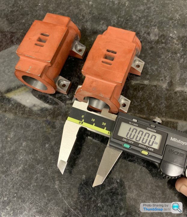
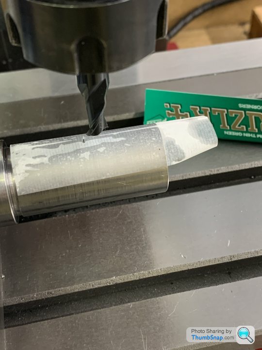
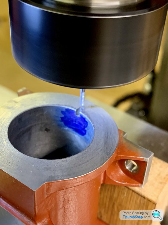
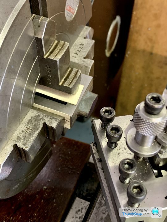
Always wanted to try using Rizla paper to find the surface of something, 0.0005” according to the verniers, so there we go…
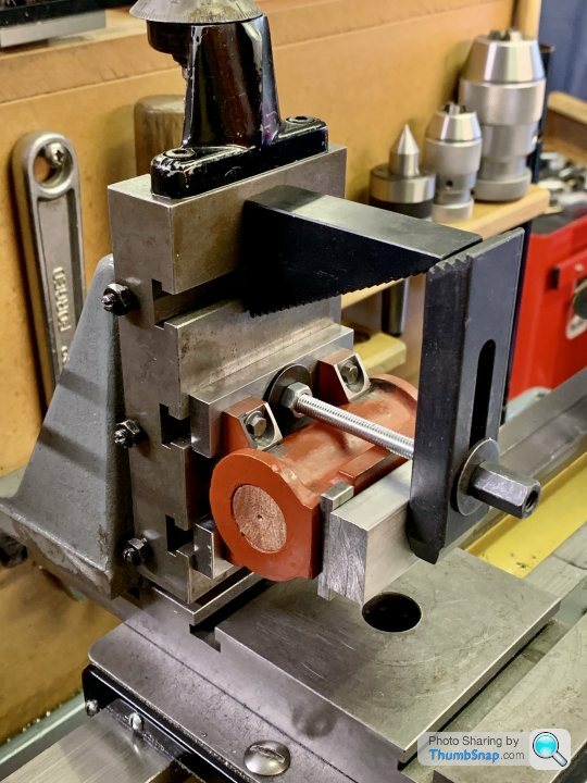
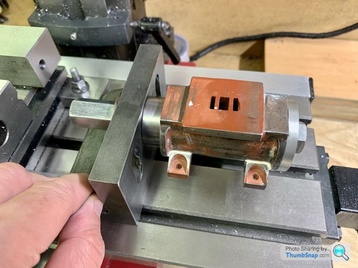
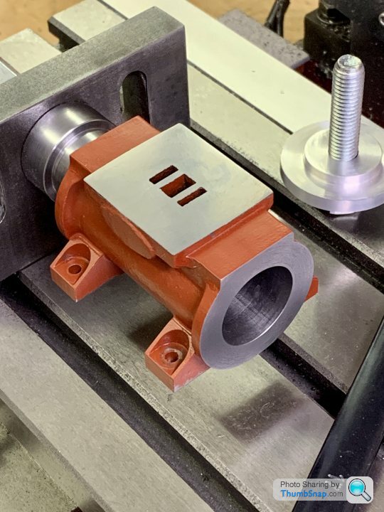
Then machined the feet using the valve face as a reference:
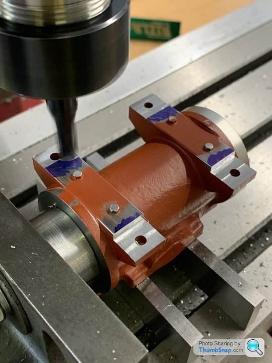
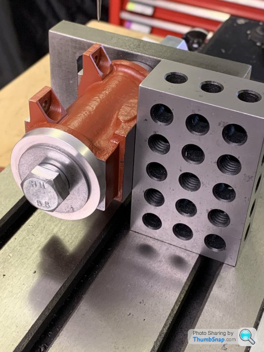
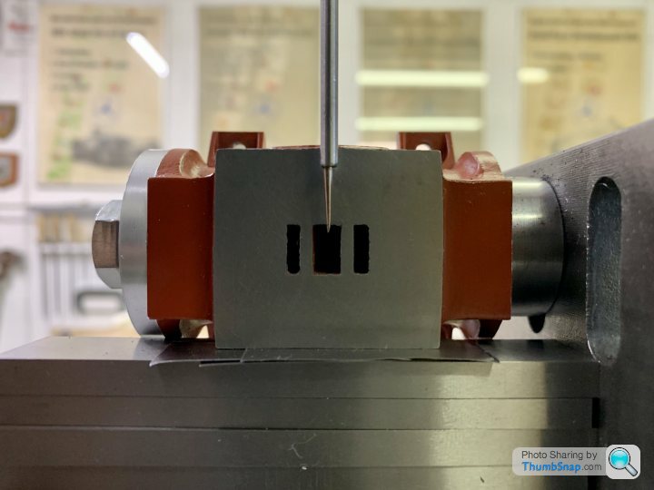
Set up at 90 degrees to the valve face using a 1-2-3 block
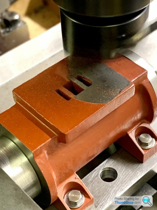
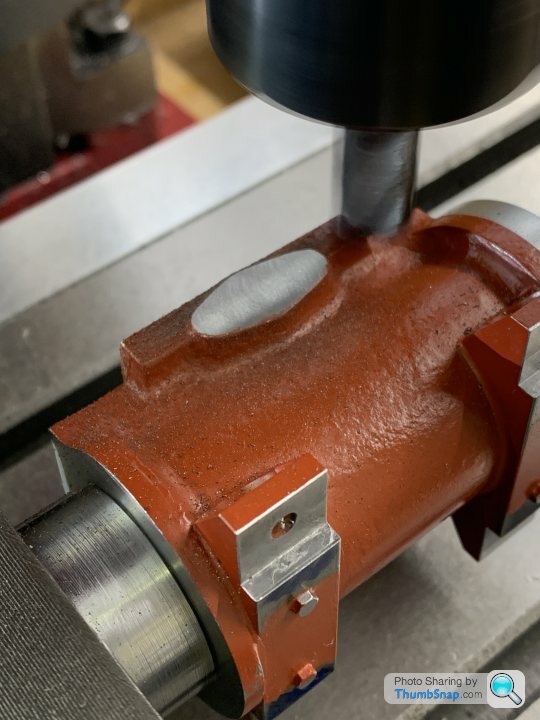
Then faced the exhaust pad with a 12mm end mill. It only just cleaned up at the specified offset from the axis
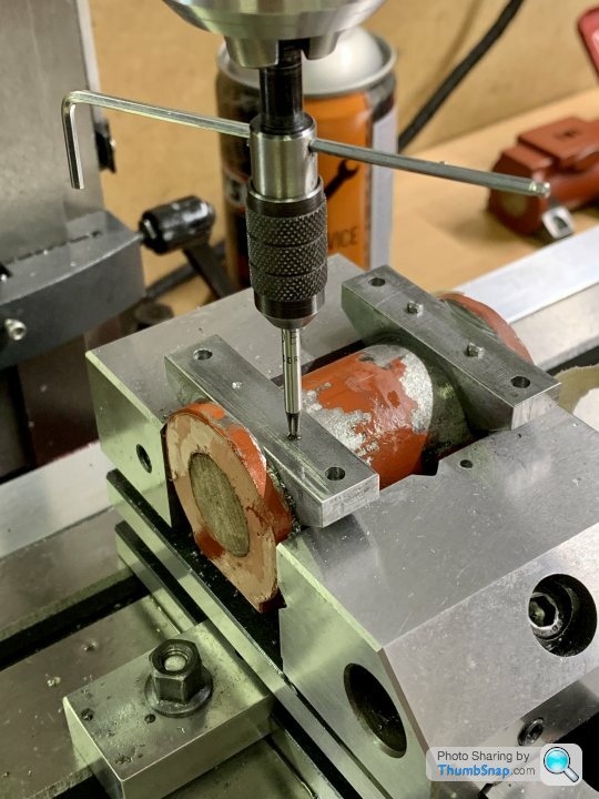
Then puzzled over whether to centre using the valve pad as the reference, or the cylinder ends. There was a very slight difference. Same with the offset from the valve face. Only a matter of 0.004” or so in both cases, but in the end I used the valve pad and the exhaust pad as references:
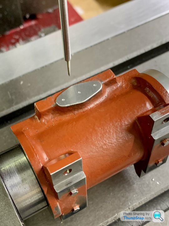
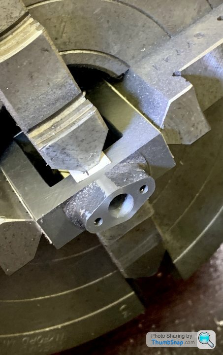
Double-check with the port seemed to confirm it was about right:
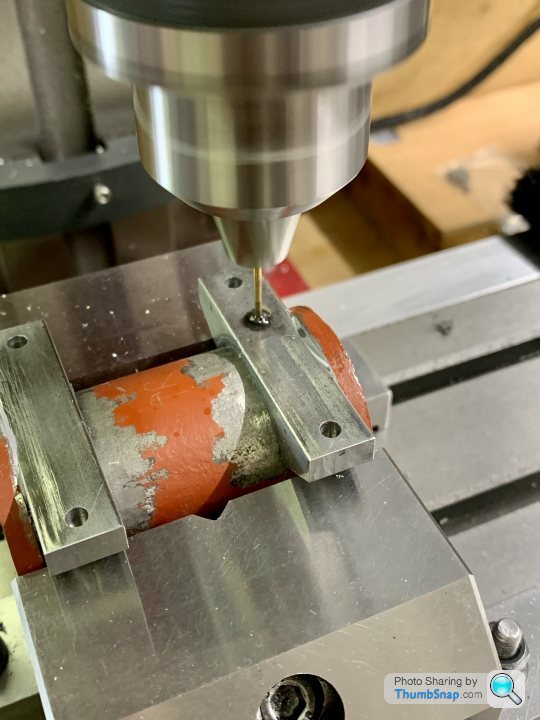
And since I’m using the DROs, I ignored the instructions to mark from the port block, and drilled and tapped the securing holes:
The exhaust hole broke through right where it should:
Now to do it all over again with the other cylinder.
Then machined the feet using the valve face as a reference:
Set up at 90 degrees to the valve face using a 1-2-3 block
Then faced the exhaust pad with a 12mm end mill. It only just cleaned up at the specified offset from the axis
Then puzzled over whether to centre using the valve pad as the reference, or the cylinder ends. There was a very slight difference. Same with the offset from the valve face. Only a matter of 0.004” or so in both cases, but in the end I used the valve pad and the exhaust pad as references:
Double-check with the port seemed to confirm it was about right:
And since I’m using the DROs, I ignored the instructions to mark from the port block, and drilled and tapped the securing holes:
The exhaust hole broke through right where it should:
Now to do it all over again with the other cylinder.
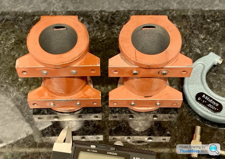
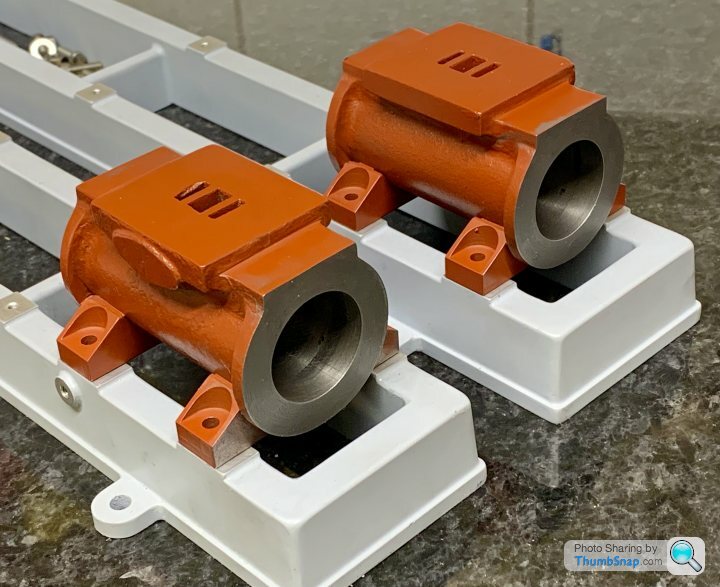
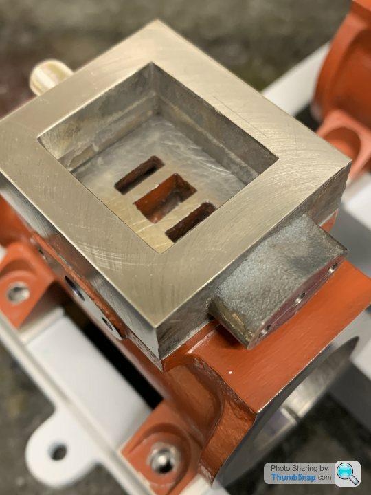
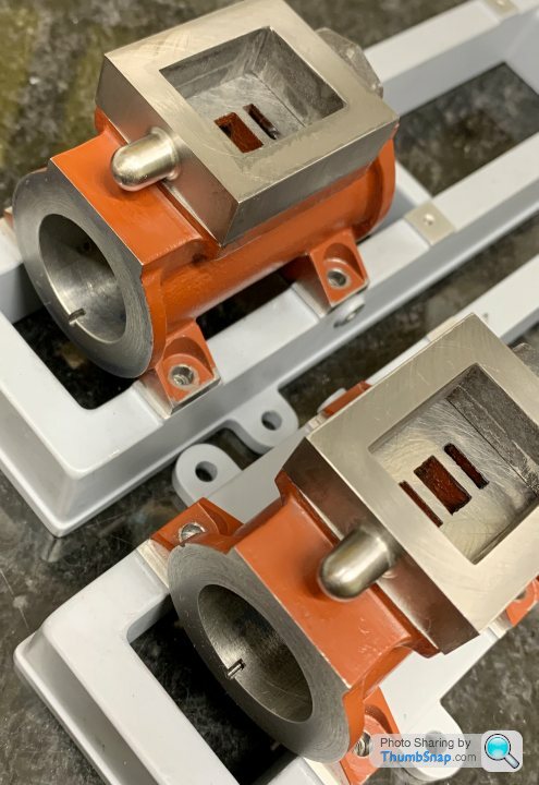
Struggling with motivation do to anything at the moment - maybe I’ve got too many projects on, or maybe it’s delayed lockdown blues. Anyway, got the other cylinder exhaust port and feet done:

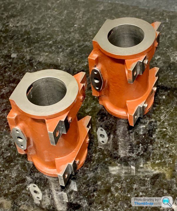
They both seem to be ok in terms of heights and lengths etc., and the thickened Milliput flange isn’t really noticeable either. So the next thing I want to get done are the angled drillings for the drain cocks. I think I’ll drill and tap the feet for the cocks (or unions), then angle the cylinders in the vice and use the long series centre drill to start a hole, then drill and hope it breaks into the drain cock hole…
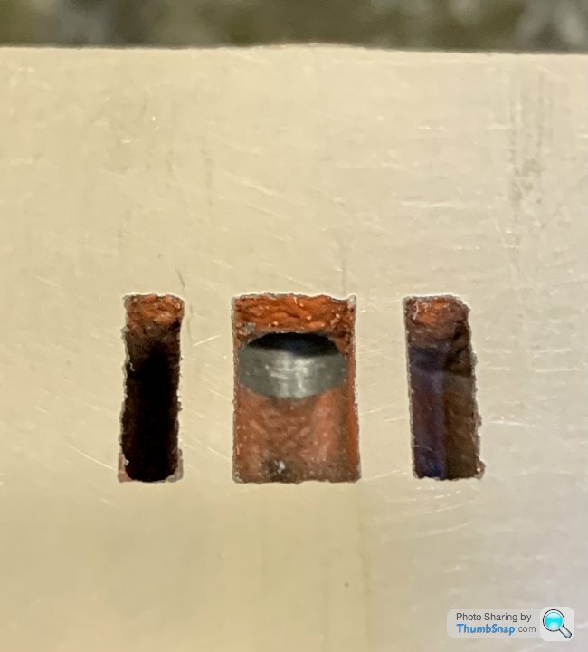
Then it’ll be on to drilling the cylinder cover holes and figuring out some revised hole positions for the valve chests:

That will be interesting seeing as they are a bit small, and the corner holes seem to have wafer thin edges.
They both seem to be ok in terms of heights and lengths etc., and the thickened Milliput flange isn’t really noticeable either. So the next thing I want to get done are the angled drillings for the drain cocks. I think I’ll drill and tap the feet for the cocks (or unions), then angle the cylinders in the vice and use the long series centre drill to start a hole, then drill and hope it breaks into the drain cock hole…
Then it’ll be on to drilling the cylinder cover holes and figuring out some revised hole positions for the valve chests:
That will be interesting seeing as they are a bit small, and the corner holes seem to have wafer thin edges.
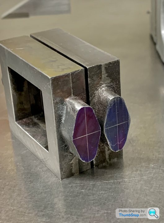
Made some progress on the steam chests today. I may have done this arse about face, but it seems to have worked…
Started by putting the chests in the 4-jaw and cleaning up the gland faces (not to any particular dimension)
Then using the height gauge, scribing the centres of the ovals by measuring the major and minor dims, and offsetting the scriber by half:

From there I could easily figure out how much to remove from the previously cleaned-up faces:


Then the sides, making them all the same as the minimum clean-up side:
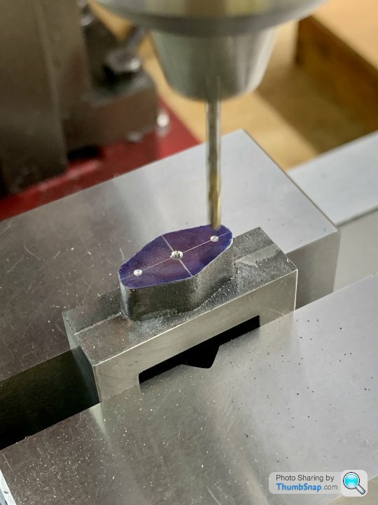
Then set up in the mill to drill some pilot holes for the flanges:
Then setup in the 4-jaw to get the valve rod hole centred (its offset). Once set, I loosened 2 of the jaws, and spun the part 180 degrees so I could machine the dome end:
This cleaned up OK:
And the other:
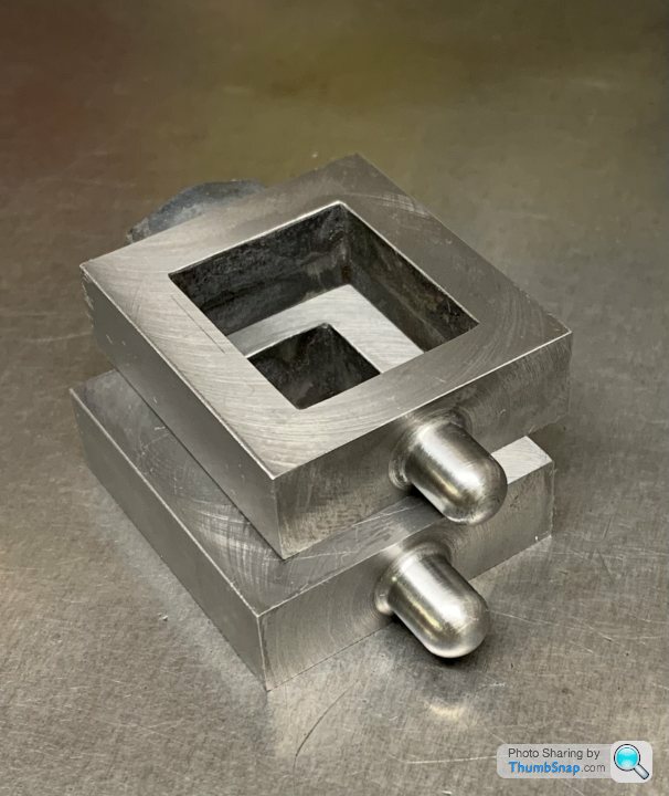
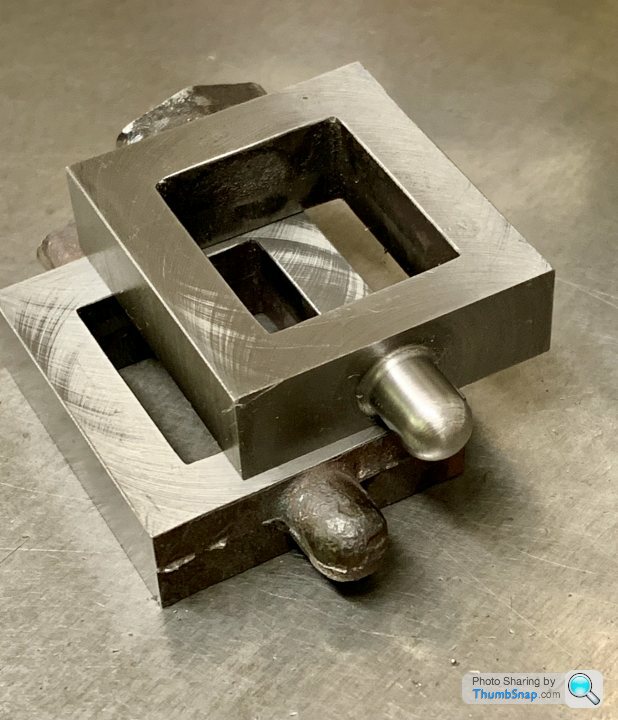
They actually measure within a few thou of each other in overall height, which is surprising since the end facing of the ovals wasn’t to a dimension yet:

Slightly concerning that even without the oval ends being machined, they’re very short to the valve face pads:
Still, I only did the absolute minimum clean-up so it is what it is:

Very pleased with the height gauge - it got lots of use already, and made things so much easier for these parts. Now waiting for the RT to arrive - just in time for profiling the oval bosses.
BTW, also increased the drain slots from 2mm to 3mm long.
Started by putting the chests in the 4-jaw and cleaning up the gland faces (not to any particular dimension)
Then using the height gauge, scribing the centres of the ovals by measuring the major and minor dims, and offsetting the scriber by half:
From there I could easily figure out how much to remove from the previously cleaned-up faces:
Then the sides, making them all the same as the minimum clean-up side:
Then set up in the mill to drill some pilot holes for the flanges:
Then setup in the 4-jaw to get the valve rod hole centred (its offset). Once set, I loosened 2 of the jaws, and spun the part 180 degrees so I could machine the dome end:
This cleaned up OK:
And the other:
They actually measure within a few thou of each other in overall height, which is surprising since the end facing of the ovals wasn’t to a dimension yet:
Slightly concerning that even without the oval ends being machined, they’re very short to the valve face pads:
Still, I only did the absolute minimum clean-up so it is what it is:
Very pleased with the height gauge - it got lots of use already, and made things so much easier for these parts. Now waiting for the RT to arrive - just in time for profiling the oval bosses.
BTW, also increased the drain slots from 2mm to 3mm long.
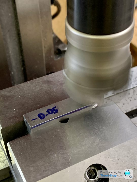
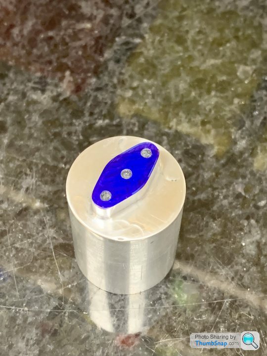
Had a day off work today, so cracked on with the valve rod gland bosses. I want the gunmetal glands to match the shape of the bosses, at the moment they are different. I figured out some geometry that should enable me to use the R/T to mill them together. Did a test on some aluminium, that worked ok:
So on to the real thing: mounted the chests in the 4 jaw chuck and skimmed the faces to give a consistent depth datum to mill to:
Then drilled the valve rod holes and packing space:
Also faced the boss again to get the right protrusion:
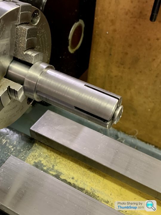
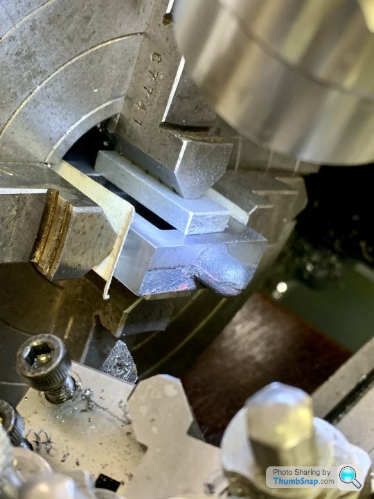
Then set the gunmetal extrusion in the 4-jaw and turned the spigot to fit the packing hole:
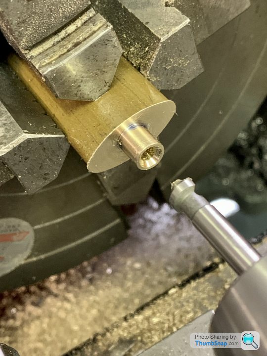
Didn’t fancy parting it off, so went at it with the hacksaw:

Then reversed it and put in the collet chuck to face the front:
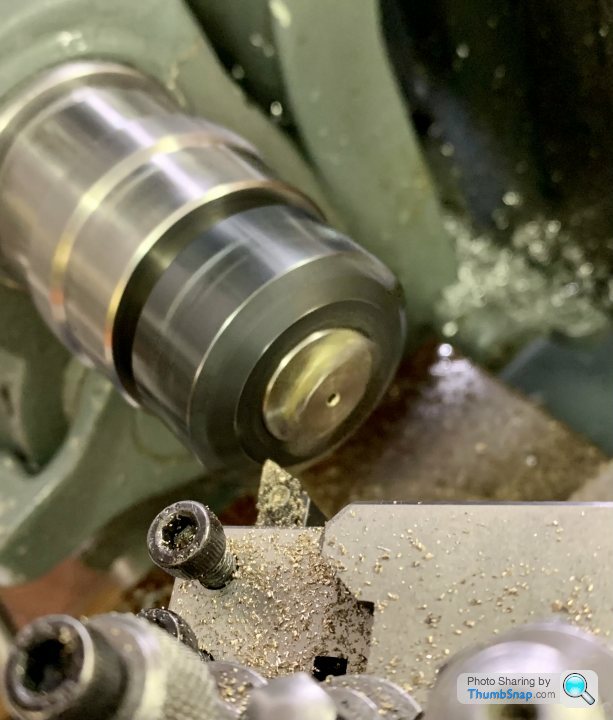
Finished:
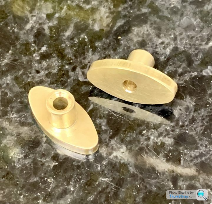
Just need the 7BA clearance holes drilling, then I can bolt them to the chests for milling the sides:
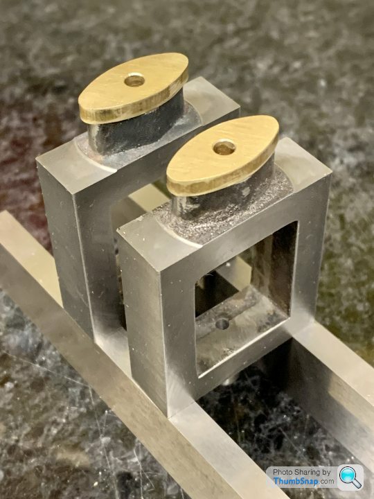
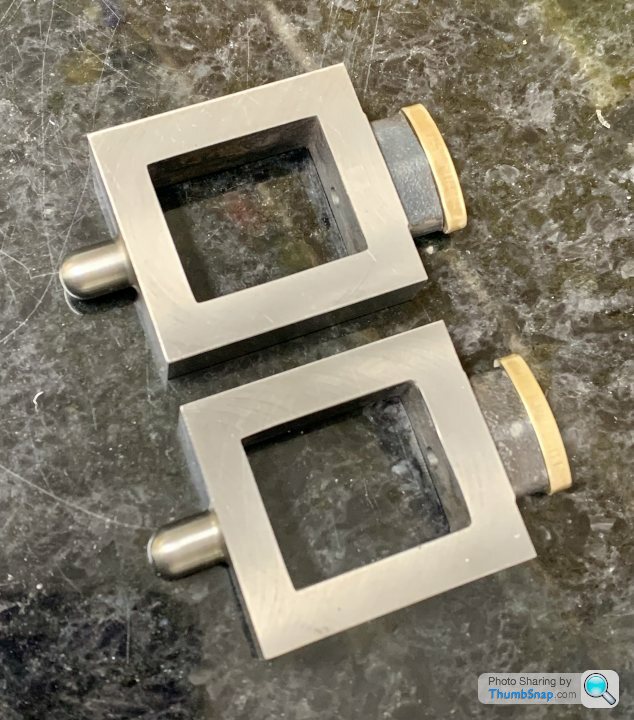
You can see how oversized the gunmetal is here:

If I’ve done my sums right, the mill profile should just skim the cast iron boss and in the process take the excess gunmetal with it, leaving them identical.
So on to the real thing: mounted the chests in the 4 jaw chuck and skimmed the faces to give a consistent depth datum to mill to:
Then drilled the valve rod holes and packing space:
Also faced the boss again to get the right protrusion:
Then set the gunmetal extrusion in the 4-jaw and turned the spigot to fit the packing hole:
Didn’t fancy parting it off, so went at it with the hacksaw:
Then reversed it and put in the collet chuck to face the front:
Finished:
Just need the 7BA clearance holes drilling, then I can bolt them to the chests for milling the sides:
You can see how oversized the gunmetal is here:
If I’ve done my sums right, the mill profile should just skim the cast iron boss and in the process take the excess gunmetal with it, leaving them identical.
Gassing Station | Scale Models | Top of Page | What's New | My Stuff