Radio panel refurb with Savage hazard switch
Discussion


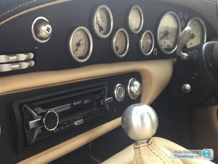
My 1995 Chimaera initially came with a flimsy piece of painted steel instead of a proper radio panel (early type) so I managed to buy a panel that needed refurbishment from a scrapyard. The plastic warning symbol strips pushed out easily and cleaned up well with some 2000 wet and dry followed by some Plast-RX which I've used before to clean up the rear window perspex. I then re-veneered the panel with American burr walnut.
I wanted to upgrade the original switchgear as my original ones were pretty battered and abused plus I was after a uniform look with symbols for the light switches on the left of the panel. I've seen from the posts here that the Savage Switches are quite popular so I went for those.
Are there any other alternatives with symbols on the buttons? Anyone tried and adapted the Caterham switches?
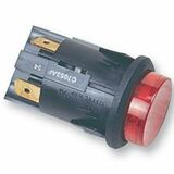
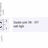
The original hazard switch (C7053AFNAA) is an illuminated DPST (double pole single throw) switch that you can still buy easily from such companies as Farnell.
I looked around the net for a suitable description of how this circuit works and couldn't find one so with some investigation on my part here's an explanation.
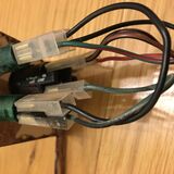
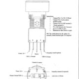
First of all there is the red feed (always on) into the switch that puts power onto the double set of brown/black wires when the switch is pressed in. On the other side of the switch there is a feed in from the right hand side (RHS) flasher indicator lamp wiring which is a double set of green/white wires. Both the green/white and brown/black wires disappear to the flasher and hazard relay circuit which isn't straightforward as there are two other relays that the standard flasher unit interacts with. I think this is covered in Steve Heath's book. Anyway, we don't need to know the details of that circuit for the purposes of the hazard light except for the following: the +12V on the brown/black wires activates the hazard relay circuit and the feed for the RHS flasher indicator lamp (green/white wires) alternates between +12V and ground. This is what powers the hazard button light.
So when you press the hazard button in, +12V goes to the hazard/flasher circuit via the brown/black wires and on the other side of the switch, those pins will alternative between +12V and ground. Both indicator lamps light up with feeds from the hazard/flasher relays and the hazard light is off as there is +12V across both sides of the switch (no voltage drop across the inbuilt light). When the indicator lamps go off, the hazard button lights up as there is now +12V on one side (red and brown/black) and the other is now at ground. The cycle then repeats.
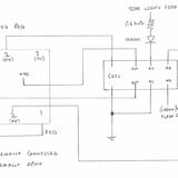
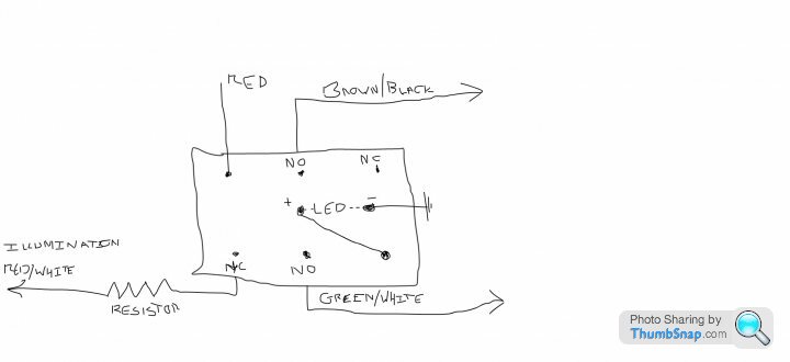
Now I had an understanding of the original circuit, I could then map this across to using the corresponding Savage switch. The only additional thing was that I wanted the new switch to light up when the side lights were on, not full brightness (as the inbuilt LED is quite bright) but a dim/soft light. To do this required a relay and the circuit I came up with is below. The relay could be any changeover relay but I just chose this one because it was cheap <£2, low power and small. The diode is used to prevent and stray voltage/current feeding back to the instrument panel lights circuit where I drew the feed from. The resistor value I chose was to lower the driving current of the switch LED to a suitable dimness. The inbuilt resistor to the switch is 390 Ohms which results in quite a bright LED.
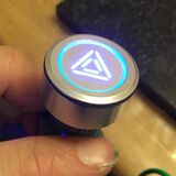
Here's a pic showing the full brightness of the switch LED before I changed the bulb to red.
The operation of this circuit now works as follows:
Hazard switch off, switch light off unless the sides are on. If illuminated then they are dimmed.
Hazard switch on, switch light flashes as per the original switch configuration at full brightness.
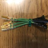
When connecting the old wiring to the new switch I used adaptor wires that I crimped up to go from the 6.3mm female to a 4mm female connector. This was to keep the originality of the wiring if I wanted to go back to the original switch or if I used a different switch in the future then I won't have to hack at my original wiring loom again. That idea worked well when I was trying out different circuits.
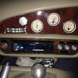
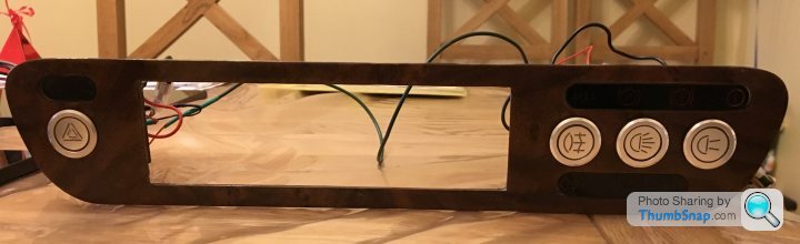
The finished radio panel with the side lights on. The American burr walnut veneer is a lot redder in natural light (I intend to refurb the painted dash above too). I'll post about the re-veneering soon.
What do people think? Are there any improvements to these circuits to be made or better switches out there?
Hope this is a useful explanation of this circuit for everyone and I'd appreciate your thoughts.
I wanted to upgrade the original switchgear as my original ones were pretty battered and abused plus I was after a uniform look with symbols for the light switches on the left of the panel. I've seen from the posts here that the Savage Switches are quite popular so I went for those.
Are there any other alternatives with symbols on the buttons? Anyone tried and adapted the Caterham switches?
The original hazard switch (C7053AFNAA) is an illuminated DPST (double pole single throw) switch that you can still buy easily from such companies as Farnell.
I looked around the net for a suitable description of how this circuit works and couldn't find one so with some investigation on my part here's an explanation.
First of all there is the red feed (always on) into the switch that puts power onto the double set of brown/black wires when the switch is pressed in. On the other side of the switch there is a feed in from the right hand side (RHS) flasher indicator lamp wiring which is a double set of green/white wires. Both the green/white and brown/black wires disappear to the flasher and hazard relay circuit which isn't straightforward as there are two other relays that the standard flasher unit interacts with. I think this is covered in Steve Heath's book. Anyway, we don't need to know the details of that circuit for the purposes of the hazard light except for the following: the +12V on the brown/black wires activates the hazard relay circuit and the feed for the RHS flasher indicator lamp (green/white wires) alternates between +12V and ground. This is what powers the hazard button light.
So when you press the hazard button in, +12V goes to the hazard/flasher circuit via the brown/black wires and on the other side of the switch, those pins will alternative between +12V and ground. Both indicator lamps light up with feeds from the hazard/flasher relays and the hazard light is off as there is +12V across both sides of the switch (no voltage drop across the inbuilt light). When the indicator lamps go off, the hazard button lights up as there is now +12V on one side (red and brown/black) and the other is now at ground. The cycle then repeats.
Now I had an understanding of the original circuit, I could then map this across to using the corresponding Savage switch. The only additional thing was that I wanted the new switch to light up when the side lights were on, not full brightness (as the inbuilt LED is quite bright) but a dim/soft light. To do this required a relay and the circuit I came up with is below. The relay could be any changeover relay but I just chose this one because it was cheap <£2, low power and small. The diode is used to prevent and stray voltage/current feeding back to the instrument panel lights circuit where I drew the feed from. The resistor value I chose was to lower the driving current of the switch LED to a suitable dimness. The inbuilt resistor to the switch is 390 Ohms which results in quite a bright LED.
Here's a pic showing the full brightness of the switch LED before I changed the bulb to red.
The operation of this circuit now works as follows:
Hazard switch off, switch light off unless the sides are on. If illuminated then they are dimmed.
Hazard switch on, switch light flashes as per the original switch configuration at full brightness.
When connecting the old wiring to the new switch I used adaptor wires that I crimped up to go from the 6.3mm female to a 4mm female connector. This was to keep the originality of the wiring if I wanted to go back to the original switch or if I used a different switch in the future then I won't have to hack at my original wiring loom again. That idea worked well when I was trying out different circuits.
The finished radio panel with the side lights on. The American burr walnut veneer is a lot redder in natural light (I intend to refurb the painted dash above too). I'll post about the re-veneering soon.
What do people think? Are there any improvements to these circuits to be made or better switches out there?
Hope this is a useful explanation of this circuit for everyone and I'd appreciate your thoughts.
I did some research into how best to veneer the metal and contacted a couple of veneering companies in the UK. The method I settled on took into account the following:
Anyway, after I'd contacted the veneering specialists, I bought the following materials:
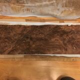
A piece of cheap walnut veneer (crown cut I think at <£6 for 1.8m), American burr walnut (2 sheets for £25 at 75cmx25cm each to do the main dash too), Gorilla glue (£5) and Titebond cold veneer glue (I must admit this was good stuff and didn't have any glue bleed-through that people talk about, £12). Plus for general bits and the finishing some polyurethane outdoor varnish I had, meths for cleaning, wet and dry of various grades up to 1200 grit, Halford water based rubbing compound, B&Q dark water based filler, my daughter's felt tip pens to colour any filled areas (don't laugh it worked well!) and Plast-RX for the final polish.
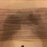
Pics of the cheap intermediate veneer and the American burr walnut:
Glues

The burr veneer can be a bit wavy when you receive it from any supplier so I wetted it down with water and clamped it between 2 pieces of wood with paper towel as separators for a week to flatten it first. Doesn't need to be super flat and if you want to go the extra mile then you can use a 10% glycerine solution (buy the glycerine from any supermarket) to aid the flattening process.
I then settled on the following method which the veneer people said was a bit over the top but would give a very strong and lasting result.
Cleaned up the metal panel back to bare steel with 400 grit paper as clean as can be.
Meths on some kitchen roll to clean the steel.
Use a piece of kitchen roll lightly wetted with tap water to wipe down the steel. Not essential but it helps to catalyse the Gorilla glue (cyanoacrylate based) and also causes the glue to expand a bit more to get into the grain of the veneer applied.
Next lay on a piece of the cheap walnut veneer. The reason I used walnut veneer for this intermediate piece rather than another type was that I thought I'd use a similar piece of substrate rather than plywood. Each veneer layer is only 0.7mm thick whereas the model plywood that some people use is 1.5mm and you don't know what glues had been used to form the ply. Just my opinion but from my own woodworking experience and those of the veneering companies, I decided against the plywood method. The crown cut veneer laying length-ways along the radio panel helps with flex too.
So, next I wrapped the glued piece in a layer of cling-film and then clamped the piece between two layers of wood with lots of F-Clamps. The cling-film prevents the metal/veneer sandwich sticking to the wood clamp pieces when the glue squishes out. Simple but effective.
Leave overnight.
Trim back roughly with a Stanley knife.
Apply a generous layer of Titebond glue to the layer of veneer
Stick on a piece of the flat burr veneer
Cling-film and clamp again overnight
Trim back using a Stanley knife and or fine bladed junior hacksaw. The holes I took my time with and ended up wrapping a piece of sand paper around a round file to trim the veneers back to the steel. I used same method to carefully take the veneers back to the steel for the outside of the panel too. Carefully does it as the burr veneer can chip easily at this stage.
Fill any odd chips with filler, sand back with wet and dry and dye accordingly.
Sand the burr veneer as needed, probably 400 grit paper here. The veneer is generally supplied quite smooth so a light sand is generally all that is required.
This sandwich method allows a wood substrate to be strongly bonded to the metal using the cyanoacrylate glue without fear of bleed through of the glue with the expensive burr veneer. Bleed through will give you staining on the burr. The Titebond is PVA based but is specific to veneering applications, is very strong and I have to admit is worth the money for this job. Overall you end up with a tough composite piece that can be finished using solvent based top coats, either polyurethane varnish or lacquer. I wouldn't recommend shellac or an oil finish due to longevity.
Now the finishing. I used polyurethane as it is more flexible than lacquer and is more water resilient. Yes lacquer is used on flooring but again with some research and experience went with the polyurethane.
First wipe down the burr veneer with a damp cloth.
Wipe down a couple of times with meths. This can highlight some imperfections in the wood at this stage and you can sand back and touch up accordingly. The meths tends to 'lift' the grain of the wood and roughens the surface.
Once you're happy with the flatness of the wood, colour and cleanliness then you can start to apply the top coat.
Dilute a small quantity of polyurethane down with some white spirits by 30-50% and apply to the wood using a fresh clean brush. You'll find it soaks right in and drys quickly.
I did 2 coats in this manner and lightly sanded with 800 grit wet and dry the second layer.
After that I did at least 4 coats of polyurethane and sanded in between using 800 wet and dry with water to get an even dulled surface. I wrapped the sandpaper around a large pencil rubber as a sanding block.
Once happy with the flattened layer, wipe with meths before applying the next coat.
Between each coat I let the piece dry for at least 1/2 day in my airing cupboard (just somewhere warm with little dust to settle onto the surface).
Sounds like a lot of hassle but the coats of varnish took a while to fill in all the little pores in the burr and then the colour really started to come through. Worth the patience to get it right.
Don't leave it too long between coats (>1 day) otherwise the layers don't bond well.
Final layer sand back with 1200 wet and dry with water, nice and even
Wipe with meths.
Leave overnight to set harder
Cut back with rubbing compound and water. Just like with paintwork although be gentle.
Finish with the Plast-RX. Be gentle again.
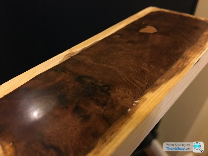
Here is a pic of my test piece fully finished. The beige splodge is an un-dyed bit of filler, the other small areas I filled you can't notice.
Finished piece before the switches went in. Not the best photo I know but it looks great under natural light.
Fitting the finished piece into the car went well and I could flex the dash in without worries about the burr splitting. All up <£70 ish I think to do both dash pieces. A lot cheaper and more satisfying doing it yourself. The metalwork cost me £54 delivered from the scrapyard.
Hope this helps and please let me know your thoughts.
- Flex of the metal backing and general flex in temp changes throughout the year.
- Adhesive type to cope with the metal/wood bonding and also taking into account the solvent used for finishing (as it soaks through the wood on curing)
- Longevity of the finish applied - to cope with temp changes in a car and also some water thrown in.
Anyway, after I'd contacted the veneering specialists, I bought the following materials:
A piece of cheap walnut veneer (crown cut I think at <£6 for 1.8m), American burr walnut (2 sheets for £25 at 75cmx25cm each to do the main dash too), Gorilla glue (£5) and Titebond cold veneer glue (I must admit this was good stuff and didn't have any glue bleed-through that people talk about, £12). Plus for general bits and the finishing some polyurethane outdoor varnish I had, meths for cleaning, wet and dry of various grades up to 1200 grit, Halford water based rubbing compound, B&Q dark water based filler, my daughter's felt tip pens to colour any filled areas (don't laugh it worked well!) and Plast-RX for the final polish.
Pics of the cheap intermediate veneer and the American burr walnut:
Glues
The burr veneer can be a bit wavy when you receive it from any supplier so I wetted it down with water and clamped it between 2 pieces of wood with paper towel as separators for a week to flatten it first. Doesn't need to be super flat and if you want to go the extra mile then you can use a 10% glycerine solution (buy the glycerine from any supermarket) to aid the flattening process.
I then settled on the following method which the veneer people said was a bit over the top but would give a very strong and lasting result.
Cleaned up the metal panel back to bare steel with 400 grit paper as clean as can be.
Meths on some kitchen roll to clean the steel.
Use a piece of kitchen roll lightly wetted with tap water to wipe down the steel. Not essential but it helps to catalyse the Gorilla glue (cyanoacrylate based) and also causes the glue to expand a bit more to get into the grain of the veneer applied.
Next lay on a piece of the cheap walnut veneer. The reason I used walnut veneer for this intermediate piece rather than another type was that I thought I'd use a similar piece of substrate rather than plywood. Each veneer layer is only 0.7mm thick whereas the model plywood that some people use is 1.5mm and you don't know what glues had been used to form the ply. Just my opinion but from my own woodworking experience and those of the veneering companies, I decided against the plywood method. The crown cut veneer laying length-ways along the radio panel helps with flex too.
So, next I wrapped the glued piece in a layer of cling-film and then clamped the piece between two layers of wood with lots of F-Clamps. The cling-film prevents the metal/veneer sandwich sticking to the wood clamp pieces when the glue squishes out. Simple but effective.
Leave overnight.
Trim back roughly with a Stanley knife.
Apply a generous layer of Titebond glue to the layer of veneer
Stick on a piece of the flat burr veneer
Cling-film and clamp again overnight
Trim back using a Stanley knife and or fine bladed junior hacksaw. The holes I took my time with and ended up wrapping a piece of sand paper around a round file to trim the veneers back to the steel. I used same method to carefully take the veneers back to the steel for the outside of the panel too. Carefully does it as the burr veneer can chip easily at this stage.
Fill any odd chips with filler, sand back with wet and dry and dye accordingly.
Sand the burr veneer as needed, probably 400 grit paper here. The veneer is generally supplied quite smooth so a light sand is generally all that is required.
This sandwich method allows a wood substrate to be strongly bonded to the metal using the cyanoacrylate glue without fear of bleed through of the glue with the expensive burr veneer. Bleed through will give you staining on the burr. The Titebond is PVA based but is specific to veneering applications, is very strong and I have to admit is worth the money for this job. Overall you end up with a tough composite piece that can be finished using solvent based top coats, either polyurethane varnish or lacquer. I wouldn't recommend shellac or an oil finish due to longevity.
Now the finishing. I used polyurethane as it is more flexible than lacquer and is more water resilient. Yes lacquer is used on flooring but again with some research and experience went with the polyurethane.
First wipe down the burr veneer with a damp cloth.
Wipe down a couple of times with meths. This can highlight some imperfections in the wood at this stage and you can sand back and touch up accordingly. The meths tends to 'lift' the grain of the wood and roughens the surface.
Once you're happy with the flatness of the wood, colour and cleanliness then you can start to apply the top coat.
Dilute a small quantity of polyurethane down with some white spirits by 30-50% and apply to the wood using a fresh clean brush. You'll find it soaks right in and drys quickly.
I did 2 coats in this manner and lightly sanded with 800 grit wet and dry the second layer.
After that I did at least 4 coats of polyurethane and sanded in between using 800 wet and dry with water to get an even dulled surface. I wrapped the sandpaper around a large pencil rubber as a sanding block.
Once happy with the flattened layer, wipe with meths before applying the next coat.
Between each coat I let the piece dry for at least 1/2 day in my airing cupboard (just somewhere warm with little dust to settle onto the surface).
Sounds like a lot of hassle but the coats of varnish took a while to fill in all the little pores in the burr and then the colour really started to come through. Worth the patience to get it right.
Don't leave it too long between coats (>1 day) otherwise the layers don't bond well.
Final layer sand back with 1200 wet and dry with water, nice and even
Wipe with meths.
Leave overnight to set harder
Cut back with rubbing compound and water. Just like with paintwork although be gentle.
Finish with the Plast-RX. Be gentle again.
Here is a pic of my test piece fully finished. The beige splodge is an un-dyed bit of filler, the other small areas I filled you can't notice.
Finished piece before the switches went in. Not the best photo I know but it looks great under natural light.
Fitting the finished piece into the car went well and I could flex the dash in without worries about the burr splitting. All up <£70 ish I think to do both dash pieces. A lot cheaper and more satisfying doing it yourself. The metalwork cost me £54 delivered from the scrapyard.
Hope this helps and please let me know your thoughts.

That looks like a very nice job to me.
I'd read on here that the original veneer eventually cracks because it and the steel it is glued to expand and contract at different rates in changes of temperature. Especially as the main top dash is slightly bent / flexed. You've done a lot of research into it and tried to counteract this so I hope it all works well.
I went the slightly easier (and cheaper) route and used carbon effect wrap on mine. I'm happy with that too. Variety is what TVRs are all about.
debaron said:
Quick q - why didn't you use the built in switch lamps? Doing exactly the same on mine.
I did use the Savage built in switch lamps. The 3 switches on the right I dimmed down with the same resistor value as with the hazard and they are all fed from the re/white wire going to the instrument panel.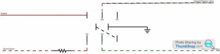
Gassing Station | Chimaera | Top of Page | What's New | My Stuff