Engine hunts when hot
Discussion


OK 4.5 Chim 2001. Engine starts ok, seems to run ok, if fact like the proverbial of the polished shovel but when it gets hot the tick over goes 2000 to 100 rpm approx and makes it almost undriveable. It is also started drinking fuel as though it is going out of fashion! 15MPG up to this poin it has been 22 mpg. I have looked at the air control servo motor, it is clean and moves in and out ok when driven by the Rover gauge from the computer. I have had this the car a few years and have replace the air control servo motor on this car about a year ago. I don't want to go down the rout of changing ecu's upgrading this and that, I just want to keep it as std as possible. Has any on ideas?
Stepper motor.
They can stick momentarily especially when hot so then out of place, Ecu doesn’t know this and chucks fuel in and out trying to compensate via lambda readings.
Itcsn sometimes be cured by simply turning off Ignition so Stepper returns back to its correct starting position, if it works fine when cold i’d Suspect this.
They often work fine when moved manually with RG or ecumate.
Find a friend with a known good Stepper motor ( idle control valve) and try that.
I had similar on my 99 car (a flake sticking out of the roof identifies it as a 99).
Mine turned out to be a faulty stepper that had previously been ok.
Proved by Rob at V8D by substituting a known working used factory original one (stepper, not flake).
I am now on Emerald and coil packs, so will go and see if i can find the stepper in the man cave.
Mine turned out to be a faulty stepper that had previously been ok.
Proved by Rob at V8D by substituting a known working used factory original one (stepper, not flake).
I am now on Emerald and coil packs, so will go and see if i can find the stepper in the man cave.
Had a quick rootle with a torch, but couldn't see it.
if I can summon up a combination of energy and decent weather I will have a go at sorting out said man cave in the next three days and see what i can find.
It may already have been donated to another owner with running problems, but could still be there somewhere.
if I can summon up a combination of energy and decent weather I will have a go at sorting out said man cave in the next three days and see what i can find.
It may already have been donated to another owner with running problems, but could still be there somewhere.
Hunting indicates a lean condition.
The trouble with the 14CUX is the airflow meter can only register air passing through it, any induction leak engine side of the airflow meter goes unseen by the airflow meter.
The idle air control valve (stepper motor) is therefore effectively an unmetetered induction leak, however the ECU does know it's possision so an enrichment correction table based on that position will exist within the ECU I'm sure.
Once the engine is fully warmed the 14CUX will also compensate for minor induction leaks by virtue of the narrow band lambda sensor supported closed loop strategy but there is only so much correction it can offer, the system in closed loop also shoots for a 14.7:1 air fuel ratio for emissions which is already very lean.
So if the stepper motor is stuck open but the ECU thinks its in a more closed position the stepper motor enrighment correction table will have little or no effect, and the airflow meter can't help you either, so you're only left with the closed loop strategy which being the earlier tech and rather crude narrow band lambda sensor type is always going to struggle.
Of course its not just the idle extra air circuit thats an intentional unmetered induction leak, the carbon canister is another one as is the crankcase breather system.
To identify the source of any excessive induction leaks by far the best tool to reach for is a simple hose clamp, clamp each hose in turn and listen for a change in idle quality, if the hunting goes away you've found your induction leak.
ChimpOnGas said:
Hunting indicates a lean condition.
The trouble with the 14CUX is the airflow meter can only register air passing through it, any induction leak engine side of the airflow meter goes unseen by the airflow meter.
The idle air control valve (stepper motor) is therefore effectively an unmetetered induction leak, however the ECU does know it's possision so an enrichment correction table based on that position will exist within the ECU I'm sure.
Once the engine is fully warmed the 14CUX will also compensate for minor induction leaks by virtue of the narrow band lambda sensor supported closed loop strategy but there is only so much correction it can offer, the system in closed loop also shoots for a 14.7:1 air fuel ratio for emissions which is already very lean.
So if the stepper motor is stuck open but the ECU thinks its in a more closed position the stepper motor enrighment correction table will have little or no effect, and the airflow meter can't help you either, so you're only left with the closed loop strategy which being the earlier tech and rather crude narrow band lambda sensor type is always going to struggle.
Of course its not just the idle extra air circuit thats an intentional unmetered induction leak, the carbon canister is another one as is the crankcase breather system.
To identify the source of any excessive induction leaks by far the best tool to reach for is a simple hose clamp, clamp each hose in turn and listen for a change in idle quality, if the hunting goes away you've found your induction leak.
The air feed for the stepper is downwind of the AFM, so is metered, so there is no need for any other compensation to the mixture. Certainly apart from a sticky stepper motor, air leaks do completely mix up the mixture control and idle. Another thing to try is unplug the stepper if you can get a steady idle and see if the idle remains stable from that point on a warm engine.If it does not you may a have a variable air leak or possibly an HT problem causing you to loose a cylinder intermittently. The point about unplugging the stepper is it locks the air feed at idle, so any change in RPM after this point is not caused by the ECU trying to control the airflow or RPM. Mind you- if the MPG has dropped, id be looking at a rich mixture due most likely due to AFM failure.The trouble with the 14CUX is the airflow meter can only register air passing through it, any induction leak engine side of the airflow meter goes unseen by the airflow meter.
The idle air control valve (stepper motor) is therefore effectively an unmetetered induction leak, however the ECU does know it's possision so an enrichment correction table based on that position will exist within the ECU I'm sure.
Once the engine is fully warmed the 14CUX will also compensate for minor induction leaks by virtue of the narrow band lambda sensor supported closed loop strategy but there is only so much correction it can offer, the system in closed loop also shoots for a 14.7:1 air fuel ratio for emissions which is already very lean.
So if the stepper motor is stuck open but the ECU thinks its in a more closed position the stepper motor enrighment correction table will have little or no effect, and the airflow meter can't help you either, so you're only left with the closed loop strategy which being the earlier tech and rather crude narrow band lambda sensor type is always going to struggle.
Of course its not just the idle extra air circuit thats an intentional unmetered induction leak, the carbon canister is another one as is the crankcase breather system.
To identify the source of any excessive induction leaks by far the best tool to reach for is a simple hose clamp, clamp each hose in turn and listen for a change in idle quality, if the hunting goes away you've found your induction leak.
Edited by blitzracing on Sunday 8th December 20:47
LenChim said:
Ok I will look at the afm.
Rimmers (Landrover spares place) sell this one, but you will need to check that it's the correct parthttps://rimmerbros.com/Item--i-ERR5595P £114
They also list the Landrover genuine one - £875.39 plus a £240 exchange surcharge.

It would appear that Jaguar Landrover are urinary removal contractors
Try this from Mark Adams- the critical bit is the warm up spike:
Most airflow meter faults will cause the engine to run excessively rich. However if the airflow meter remains connected whilst defective then the vehicle will probably not run. In most cases the output from a defective airflow meter will be in the range 2.0-2.5 Volts, which is a viable value. This represents a moderate load and will cause heavy over-fuelling without setting a fault code.
Testing is performed in the following manner. Peel back the rubber boot on the airflow meter connector and leave it plugged in to the airflow meter. Set up the digital multimeter to read voltage. Insert the negative probe into the Red/Black wire (sensor ground), and the positive into the Blue/Green wire (Airflow signal).
Turn on the ignition, but do not start the engine. The meter should immediately indicate a reading of approximately 0.3-0.34 Volts after the initial "warm up" spike. Most defective airflow meters will overshoot to 0.8 Volts or higher, and take at least 2 seconds to come down to the correct voltage.
Now start the engine, and the reading should rise to 1.6 Volts (3.5 Litre engine) to 1.75 Volts (5.0 Litre engine).
blitzracing said:
Try this from Mark Adams- the critical bit is the warm up spike:
Most airflow meter faults will cause the engine to run excessively rich. However if the airflow meter remains connected whilst defective then the vehicle will probably not run. In most cases the output from a defective airflow meter will be in the range 2.0-2.5 Volts, which is a viable value. This represents a moderate load and will cause heavy over-fuelling without setting a fault code.
Testing is performed in the following manner. Peel back the rubber boot on the airflow meter connector and leave it plugged in to the airflow meter. Set up the digital multimeter to read voltage. Insert the negative probe into the Red/Black wire (sensor ground), and the positive into the Blue/Green wire (Airflow signal).
Turn on the ignition, but do not start the engine. The meter should immediately indicate a reading of approximately 0.3-0.34 Volts after the initial "warm up" spike. Most defective airflow meters will overshoot to 0.8 Volts or higher, and take at least 2 seconds to come down to the correct voltage.
Now start the engine, and the reading should rise to 1.6 Volts (3.5 Litre engine) to 1.75 Volts (5.0 Litre engine).
Ok , Now I have measured the voltage ignition ON 1 volt, with the engine running I get 1.9 - 2.0 volts. I have an analog VM. It does have a 0.1 volt scale so I would have thought it would be reasonable accurate on a 3 volt scale but I have just asked a friend if he has a more accurate and calibrated unit to try. So just waiting to see if he can come up with the goods.Most airflow meter faults will cause the engine to run excessively rich. However if the airflow meter remains connected whilst defective then the vehicle will probably not run. In most cases the output from a defective airflow meter will be in the range 2.0-2.5 Volts, which is a viable value. This represents a moderate load and will cause heavy over-fuelling without setting a fault code.
Testing is performed in the following manner. Peel back the rubber boot on the airflow meter connector and leave it plugged in to the airflow meter. Set up the digital multimeter to read voltage. Insert the negative probe into the Red/Black wire (sensor ground), and the positive into the Blue/Green wire (Airflow signal).
Turn on the ignition, but do not start the engine. The meter should immediately indicate a reading of approximately 0.3-0.34 Volts after the initial "warm up" spike. Most defective airflow meters will overshoot to 0.8 Volts or higher, and take at least 2 seconds to come down to the correct voltage.
Now start the engine, and the reading should rise to 1.6 Volts (3.5 Litre engine) to 1.75 Volts (5.0 Litre engine).
This is what it should look like- the important bit is the 1/2 second pulse to 5v to start with, and the fact it becomes stable quickly- and in my case its reading 1.62v on starting my engine (a 3.9). Yours is a bit high unless the RPM is above idle? The faulty ones have a much slower spike over several seconds before they become stable
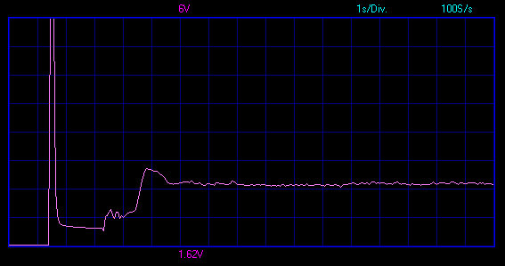
Ok I see the line ins that from an oscilloscope? Any way whilst I am waiting for a better piece of measuring kit i have been looking on line for afm's it seems there are at lot out there, TVR parts tell me that the afm is the same on a Chim 4li through to 5li, if that's the case is it the same as a Land Rover V8 unit an ERR5198G? £55.00. TVR part number E2036 @£189.55 +VAT =£227.46 But and there is always a but this item looks to have the same plug socket but it has 6 pins in it my unit on the car has only 5 ins but has a space for the sixth. is there some other function that I do not know about in there?
This ERR5198G is supposed to be compatible with the 3.9 li 211HP Rover all the way up to the 6li Jag 311HP.
Any one had any experience with this?
Many thank.
This ERR5198G is supposed to be compatible with the 3.9 li 211HP Rover all the way up to the 6li Jag 311HP.
Any one had any experience with this?
Many thank.
There are two basic AFM's out there - the older Hitachi 3AM, and the later Lucas 5 AM, and although plug compatible there is an extra pin in one of them that is not used. The basic body / electronics of the common 5 AM is the same across all TVRs, Range Rovers and Discoveries, but the castings that bolt onto the ends vary a bit depending on the air pipework, but worse case is you have to swap over the castings from your faulty one and make up some new cardboard gaskets. There are lots of cheap unbranded 5AM replicas out on Ebay from China, and you might get lucky and get one that works, but its pot luck as the TVR environment is very hot so calibration may not be stable. Personally Id be happier with a second hand unit of a Range Rover Classic or Discovery.
As for testing and you have RoverGauge- are the AFM readings in spec at idle? What is the long fuel trim and short term trim showing? A faulty AFM may not throw a fault code, but there will be clues. If you had not said about the MPG, id still be going down the air leak route as per COGs post as a small air leak plays havoc with the idle control as the ECU is constantly trying to fix a problem it cant with stepper control.. Mind you extra air at idle could force the long term fuel trim to be too rich to try and compensate, but you will see this in RoverGauge. Worth dropping a plug out and see if its sooty.
As for testing and you have RoverGauge- are the AFM readings in spec at idle? What is the long fuel trim and short term trim showing? A faulty AFM may not throw a fault code, but there will be clues. If you had not said about the MPG, id still be going down the air leak route as per COGs post as a small air leak plays havoc with the idle control as the ECU is constantly trying to fix a problem it cant with stepper control.. Mind you extra air at idle could force the long term fuel trim to be too rich to try and compensate, but you will see this in RoverGauge. Worth dropping a plug out and see if its sooty.
This AFM availability issue and the hard life they have in the TVR aplication is a real problem for the future our cars 
I wonder if there's a quality alternaive from common mass produced car that someone clever with electronics could adapt so the 14CUX ECU is happy with the AFM output
Correct load sensing is certainly essential for a smooth driving TVR, dispite going with an aftermarket ECU I've suffered the effects of a cheap Chinese Vauxhall MaP sensor being used by the installers, replacing it with a quality MaP sensor from NTK transformed my Canems equiped Chimaera.
That Japanese MaP sensor was only £27 but not everyone wants, needs or can afford an aftermarket ECU, many also want to keep their car original so I hope someone comes up with a cost effective solution for failing Lucas AFMs as this problem is only going to get worse for Chim & Griff owners, and eventually the supply of good used AFMs from Rangies & Discos will dry up.
I've had a canems car in with running issues and that too turned out to be the MAP sensor.
On AFMs .. yes the supply will dry up eventually of good used parts. Replacement new parts are a lottery.
Blitz might well come up with a workable solution for substituting an alternative mainstream AFM in place, in the meantime Mark Adams has been using the larger Bosch AFM for years but needs a remap to suit .. Stevesprint has a similar arrangement up and running on his car.
maybe the way forwards is the replacement afm and re-chip route using a cheap-but-reliable mainstream afm .. in the meantime though there are still plenty of good used AFMs about.
I'd like to see the AFM replaced with a MAP sensor though, mounted somewhere cool rather than the heat-affected AFM position right over the exhaust manifold .. I might give that a go one day
I did the electronics to modify both the 20 AM and Bosch unit in place of the 5AM some years ago, and tested it on my car for some months. I did have some issues with stability of my circuit in a very hot engine bay mid summer, so I never put it into full production. Being analogue it was also time consuming to set up.
It made no sense going down this route anyway- its far better to have the correct base map for the AFM you are using, its more reliable and far cheaper to reproduce once you have the base maps
It would be interesting to try putting the AFM further down the inlet pipe where its cooler, but I do wonder if the extra air volume in the inlet tract would act as a delay in the AFM output rise when you floor the throttle as it only a fraction of a second delay to produce a nasty flat spot as the fuelling lags behind the engines requirements.
Edited by blitzracing on Thursday 12th December 09:22
Gassing Station | Chimaera | Top of Page | What's New | My Stuff