Air compressor pressure switch
Discussion


Hi,
I have bought a new air compressor pressure switch (ebay) and it had no electrical diagram or markings on it. (guess a china jobby)
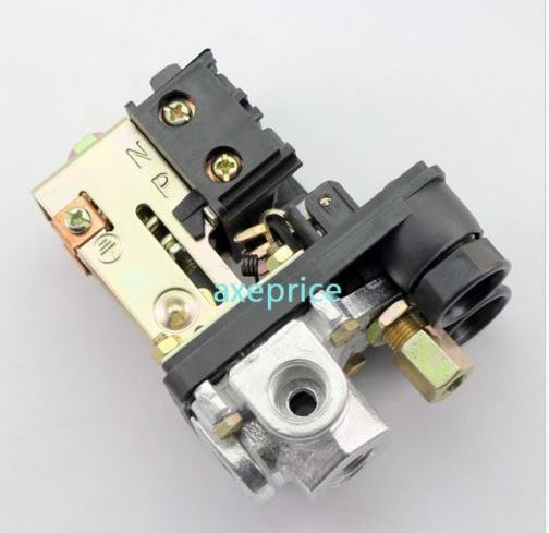
Its looks like the one below but this one does have markings.
The one below is labelled N and P - assuming neutral and P = Live ???
Any help apreciated.
I have bought a new air compressor pressure switch (ebay) and it had no electrical diagram or markings on it. (guess a china jobby)
Its looks like the one below but this one does have markings.
The one below is labelled N and P - assuming neutral and P = Live ???
Any help apreciated.
neal1980 said:
Hi,
I have bought a new air compressor pressure switch (ebay) and it had no electrical diagram or markings on it. (guess a china jobby)
Its looks like the one below but this one does have markings.
The one below is labelled N and P - assuming neutral and P = Live ???
Any help apreciated.
DC - positive/negative?I have bought a new air compressor pressure switch (ebay) and it had no electrical diagram or markings on it. (guess a china jobby)
Its looks like the one below but this one does have markings.
The one below is labelled N and P - assuming neutral and P = Live ???
Any help apreciated.
hi,
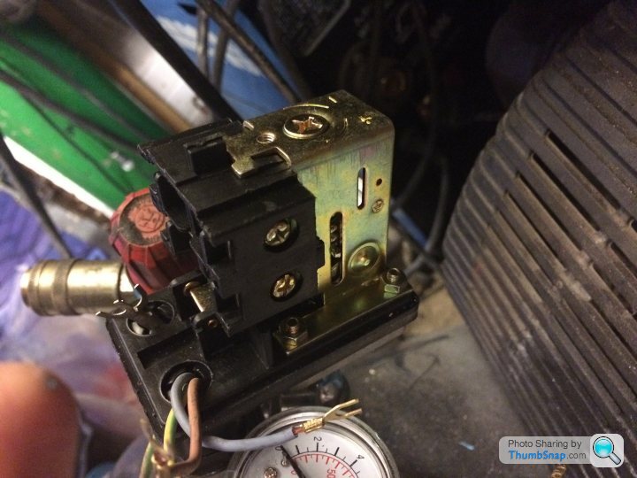
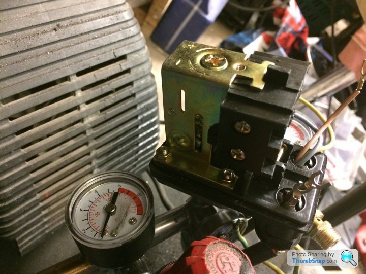
the wiring I have in place are an earth, live and neutral from plug and an earth, live and neutral from the motor. On the old switch it was labelled load and motor.
When I put a continuinty tester across the terminals the top and bottom ones are joined together and when the switch is moved both sets of terminals move up to break the connection.


From your description it seems that you have two completely separate circuits through the switch. This is normal for a switch designed to intercept the live and neutral circuits. One pair of terminals needs to be connected to the motor live and the supply live, and will connect the live side of the circuit. The other pair needs to be connected to the motor neutral and supply neutral, and will connect the neutral side of the circuit.
When the switch is 'closed' the motor will be connected to the supply live and neutral so it will run. When the switch is 'open' both motor terminals will be isolated.
When the switch is 'closed' the motor will be connected to the supply live and neutral so it will run. When the switch is 'open' both motor terminals will be isolated.


Gassing Station | Home Mechanics | Top of Page | What's New | My Stuff