2009 mitsubushi colt 1.3 strange intermittent fault
Discussion


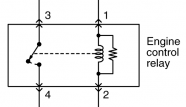
I've included a diagram of the two relays whose operation is confusing me.When i put the engine relay into place the car (i've tried three relays!)won't even turn over,engine is dead!
What should happen is pin four on engine relay should give power to pin 1 on throttle relay with ignition on.If i remove engine relay and bridge pin 3 and 4 on the junction box(which relay 'should' do itself)pin one goes live on the throttle relay as it should!
I've checked all terminals on the junction box for power with ignition on and off with both relays removed and all is good,it's just when i put both relays back into place things go tits up??
And to make things more confusing with the engine relay removed and pin 3 and 4 bridged car starts like i mentioned,but like its running on 2 cylinders,then when it warms up revs drop and it starts hunting badly!!
It either does this,or,it runs sweet as a chuffing nut!!lol???I'm thinking somethings duff in the junction box,or there's an internal fault in the ecu?Am i far off?:-)
One fault code,p1977 Etv comm error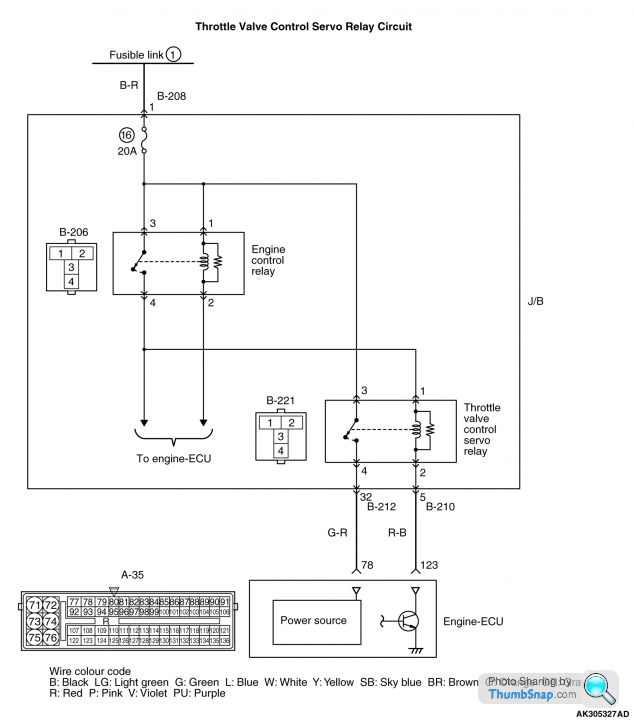
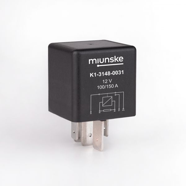
Check whether you've got the correct relay type for the engine control relay. There are two pin layouts (type A and type B) which are mechanically interchangeable but not electrically compatible.
If that isn't the problem, do a sanity check on the voltages across the engine control relay. If you have 12V across the coil and a voltage difference between the NO terminals, the relay isn't working.
The circuit diagram shows a flyback resistor across the relay coil. That type of relay is not polarity sensitive. If you replace it with a relay with a flyback diode, that is polarity sensitive and will blow the diode if connected the wrong way. If you use a relay without any flyback circuit, there's a significant risk you'll blow the driver circuit in the ECU.
I've fitted correct relays,he had another of these cars that was running,i took relays off that and nothing!It's just strange you fit relays and the car is dead,remove engine relay,bridge pin 3 and 4 on the junction box where the relay was and car starts,either runs perfect or like a bag of spanners.
When the cars starts it instantly sounds rough as hell,stays like this and the revs stay steadyish,then after a minute or two the revs start to hunt up and down constantly,or as i said it sometimes runs perfectly.
I'll check more into the wiring/connection etc,thanks for your replies!
I'll check more into the wiring/connection etc,thanks for your replies!
GreenV8S said:
The circuit diagram shows a flyback resistor across the relay coil. That type of relay is not polarity sensitive.
That's a really new one on me, I never knew you could dump back EMF with just a resistor and not include diode. Surely the presence of those resistors means they just share some of the current going through the relay coil? With out a diode I don't see how any component in that schematic can address back EMF.
GreenV8S said:
If you replace it with a relay with a flyback diode, that is polarity sensitive and will blow the diode if connected the wrong way. If you use a relay without any flyback circuit, there's a significant risk you'll blow the driver circuit in the ECU.
I agree with most of this apart from the bold bit,  which is technically not correct. If the diode is hefty enough and has a coil there in parallel then it will conduct all day long until the 20A fuse at the top of the schematic goes pop
The lack of any diode in that schematic suggests "There's a significant risk you'll blow the driver circuit in the ECU". I agree with.
To me that's a really dodgy schematic, a lot depends on what that NPN transistor doing all the work in the Engine-ECU is capable of.
It just looks all wrong to me.
(Penelope Stoppit will hopefully take a look, they/it [gender neutral label required?] seem pretty clued up on this sort of stuff).
JustALooseScrew said:
That's a really new one on me, I never knew you could dump back EMF with just a resistor and not include diode.
It may be a mistake in the drawing or my interpretation of it, but anything that conducts enough current to dissipate the EMF could be used here. It doesn't have to cope with much charge so could be a high enough resistance that the current drain be ignored. I'm struggling to imagine anyone using a big enough diode (and wiring to it) for it to survive having 12V shorted across it in the forward direction, but perhaps you know better.
GreenV8S said:
It may be a mistake in the drawing or my interpretation of it, but anything that conducts enough current to dissipate the EMF could be used here. It doesn't have to cope with much charge so could be a high enough resistance that the current drain be ignored.
I'm struggling to imagine anyone using a big enough diode (and wiring to it) for it to survive having 12V shorted across it in the forward direction, but perhaps you know better.
I not trying to teach any one to suck eggs here - but that diagram is wrong.I'm struggling to imagine anyone using a big enough diode (and wiring to it) for it to survive having 12V shorted across it in the forward direction, but perhaps you know better.
We'll just have a little bit of a think about what exactly 'Back EMF' really is.
You'll know that back in the old days the spark at the plug was caused by the points opening not closing, and the reason for that is that the points spend most of their time closed and thus pumping all that lovely sparky energy into the coil. Doing this - filling a coil full of DC 12V Energy generates a magnetic field.
When you stop pumping all that electricity in to the coil (by opening the points) that magnetic field collapses (it has nothing to keep it self sustained) and turns itself back into electricity which due to the 'magic' of a secondary coil which has many more windings than the primary charging coil turns amps into volts.
We know high voltage makes sparks and this is what is sent to the spark plug.
I've got a chinese on order which I have to collect - give me few mins and we can just run through exactly what a fly-back diode does. Little hint, think about what happens at the spark plug and decide if you want something similar but not so extreme happening at your relay contacts or your NPN semiconductor.
So in a coil pack we have a high current low voltage coil often known as the low tension side (small length of thicker wire), wrapped in conjunction low current high voltage coil known as the high tension side (very long and be thin).
After charging the low tension side and building up the magnetic field, once the points open and the field collapses it finds it easier to escape in to high tension side and generates a high voltage, low current stream that prefers to jump the gap on the spark plug, and crucially not the gap at the points.
If we think about a relay, there is only one coil in there, so when the magnetic field collapses all that energy comes back in to the same coil and flows in the opposite direction (it's what is termed reverse polarity), that current now flows against the device that energised the relay coil in the first place.
Big hunky contacts of a 10A switch can usually cope, but the intricacies of a semiconductor might struggle.
If we put diode in reverse polarity in parallel to the relay coil then during energisation, the diode doesn't conduct and all the current goes through the relay coil.
When we then switch off the relay and receive the back EMF, the diode has an easier path than the relay and the electricity flows through the diode such that this energy is dumped back in to the relay coil and not in to any controlling circuits.
Don't know if anyone found that interesting or useful or not - but that's how it works.
Penelope Stopit said:
PM sent (didn't need to send it)
Hadn't seen your latest post
You didn't need what I sent you
Yes your above post clearly explains what happens with back EMF
Nice
Thank you! I really appreciate that. Hadn't seen your latest post
You didn't need what I sent you
Yes your above post clearly explains what happens with back EMF
Nice

It's the first time that I tried to explain that and explain what really goes on.
Some times it's very hard being the lad that puts his hand up in class and says that's not quite right, in the face of some very smart and skill full people.
Especially when you think they might think you're wrong. (That's the first time I've put up a technical post here).
Anyway, back to the OP, how do we get him to sort it? It's looking a bit like the ECU might be a bit broken - but to be honest I wouldn't make any assumptions from that schematic.
JustALooseScrew said:
If we think about a relay, there is only one coil in there, so when the magnetic field collapses all that energy comes back in to the same coil and flows in the opposite direction (it's what is termed reverse polarity), that current now flows against the device that energised the relay coil in the first place.
You're on the right lines but the voltage spike is not reverse polarity in this case. The electrical inertia of the coil will tend to keep the current constant and if the ECU tries to break the circuit this will result in a spike of forward voltage across the switch, transistor etc where the circuit is being broken. The flyback circuit gives the current somewhere else to go. I don't know whether this application actually uses a resistor instead of a diode, but it's not unknown to use a resistor as well as or instead of the diode - there are pros and cons to both designs.GreenV8S said:
You're on the right lines but the voltage spike is not reverse polarity in this case. The electrical inertia of the coil will tend to keep the current constant and if the ECU tries to break the circuit this will result in a spike of forward voltage across the switch, transistor etc where the circuit is being broken. The flyback circuit gives the current somewhere else to go. I don't know whether this application actually uses a resistor instead of a diode, but it's not unknown to use a resistor as well as or instead of the diode - there are pros and cons to both designs.
Thanks, I need to go do a bit of reading on this, I appreciate your input.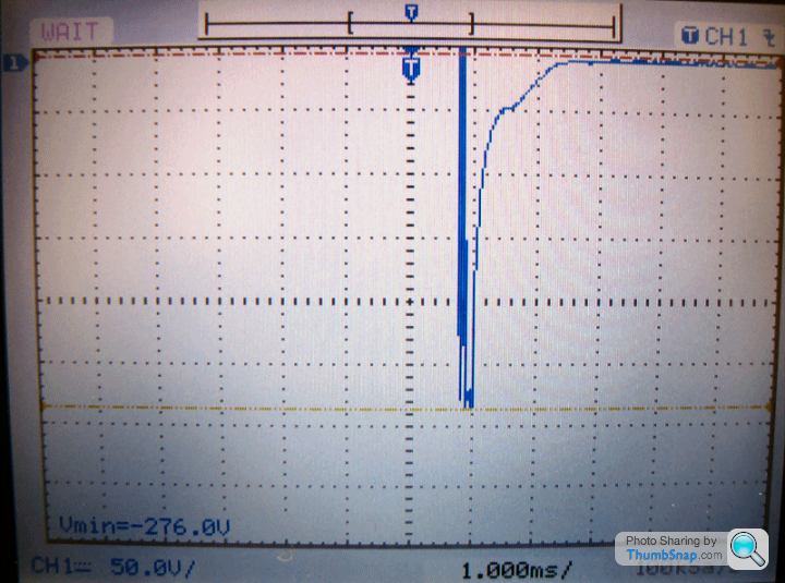
Penelope Stopit said:
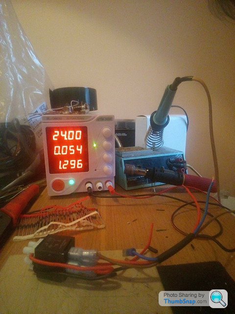
I wish there was a y-axis scale on those plots.I've just shuvved a 24V Relay on my bench PSU.
Initial switch on current was 0.068A, after a few minutes it's at 0.054A - I guess as the coils get up to temperature. So it's not a huge amount of energy ~1.3W
TBH (and reading back I didn't make this clear in my earlier posts) I generally don't bother to protect the relay coil switching circuit with fly-back diodes, but I do use these relays to switch higher inductive loads (~1Amp) and I diode protect these purely to protect the relay switching contacts.
I still reckon the schematic posted is inaccurate, that resistor is not there to deal with back EMF.
OT
BTW, I get through probably twenty 12V & twenty 24V relays a month and the prices Farnell are quoting at the moment are off the charts compared to last year and hence I've moved to a different supplier.
If you mean this above diagram, don't understand why the diagram should be wrong
Diagram is correct, it shows a resistor in parallel with a relay coil, the resistor is there to stop a back EMF of 100 plus volts reaching the Engine ECU relay control circuit
Many relay cases show the resistor when fitted
Here's more from 12 volt planet
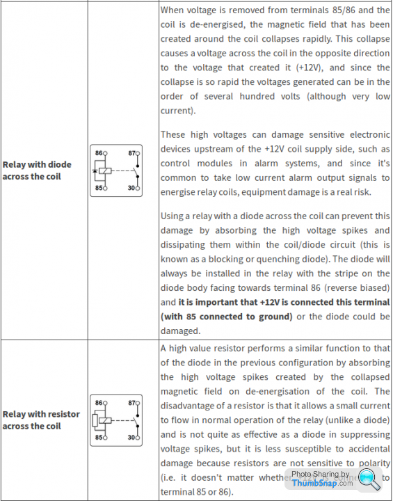
https://www.12voltplanet.co.uk/relay-guide.html
None of this has anything to do with protecting the relay contacts
Mmmm, forgot to post the Wiki Link https://en.wikipedia.org/wiki/Flyback_diode
Gassing Station | Home Mechanics | Top of Page | What's New | My Stuff