Electrical homework - gadget content within
Discussion


A bit of a fun project...
I am trying to add more LightwaveRF switching into my house, to enable Alexa more control. I would prefer to use LightwaveRF switching rather than replacing bulbs because I wish to retain the use of the current switches too.
The particular LightwaveRF switch is this one:
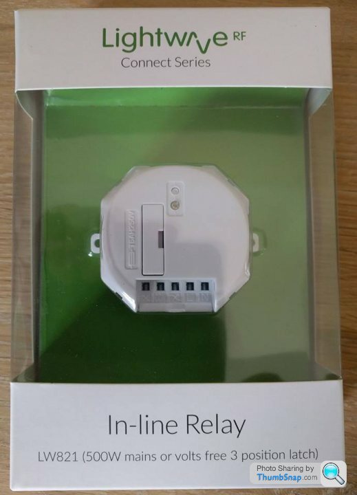
I had a mock-up working which looked like this, with the LightwaveRF relay replacing one of the end switches:

However, my house wiring isn't quite like the picture above.
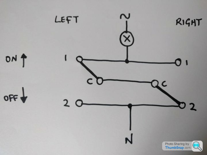
I mapped the various states of switch positions and connector voltages, thus:

Which I worked out should mean my wiring is like this:
So, first question is... have I got the circuit right?
Next question, how can I add an intermediate switch to this circuit, to make a 3-way switching?
I am trying to add more LightwaveRF switching into my house, to enable Alexa more control. I would prefer to use LightwaveRF switching rather than replacing bulbs because I wish to retain the use of the current switches too.
The particular LightwaveRF switch is this one:
I had a mock-up working which looked like this, with the LightwaveRF relay replacing one of the end switches:
However, my house wiring isn't quite like the picture above.
I mapped the various states of switch positions and connector voltages, thus:
Which I worked out should mean my wiring is like this:
So, first question is... have I got the circuit right?
Next question, how can I add an intermediate switch to this circuit, to make a 3-way switching?
I think I've got it.
The original drawing I made doesn't show where the cables enter which wall box, so I've clarified in the pic below:
Then, I can break/change some of the connections to try and make the circuit more like the one in the example of a 3-way staircase switch in my OP:
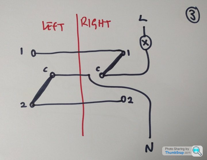
Finally, I will replace the left switch wall box with a much deeper one. Then I'll replace the left switch itself with the LightwaveRF relay (deep in the new wall box), and install an intermediate switch in front of the relay in the new left wall box. Like this:

Pretty sure this will work. Please shout before Monday if you think I'm wrong.
The original drawing I made doesn't show where the cables enter which wall box, so I've clarified in the pic below:
Then, I can break/change some of the connections to try and make the circuit more like the one in the example of a 3-way staircase switch in my OP:
Finally, I will replace the left switch wall box with a much deeper one. Then I'll replace the left switch itself with the LightwaveRF relay (deep in the new wall box), and install an intermediate switch in front of the relay in the new left wall box. Like this:
Pretty sure this will work. Please shout before Monday if you think I'm wrong.

No No No !
are you serious ? putting a switch in the neutral ?
seriously !
Live into common on first two way switch. Two strappers to the next switch, then two strappers to the final two way switch. Common from that switch to the lamp then the lamp to the neutral.
The way you have it yes you would be able to turn the lamp out but it would still be live and could give a shock if you were changing a broken bulb.
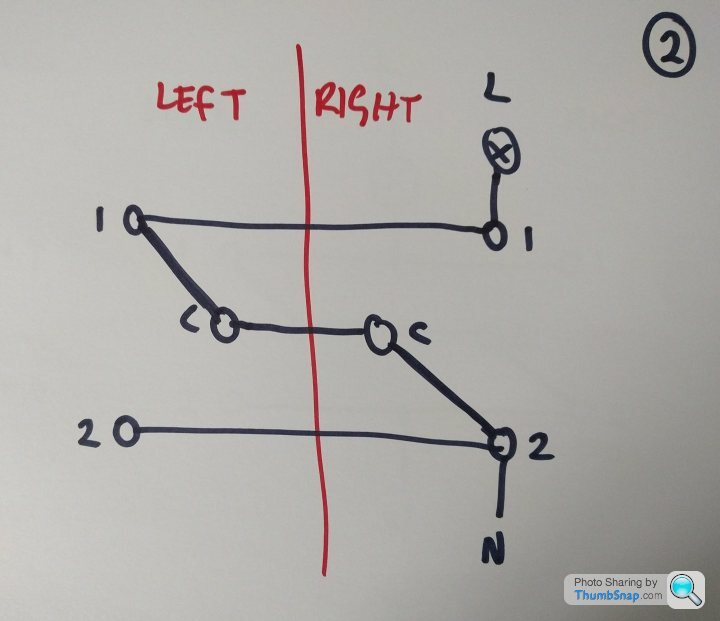
Actually, you're right - the bulb is connected to the N below.
Does that make more sense?
I only actually measured the voltage at the switches and made the assumption about the bulb. In the context of it switching on or off, it'd work both ways but you're right that it would be in the neutral part of the circuit rather than the live.
Does that make more sense?
I only actually measured the voltage at the switches and made the assumption about the bulb. In the context of it switching on or off, it'd work both ways but you're right that it would be in the neutral part of the circuit rather than the live.
Edited by Watchman on Saturday 22 July 22:09
Well, it works... kind of.
If I implement the circuit with actual switches, it all performs as expected. All switches can change the state, whatever it is.
But when replacing one of the end switches with the LWRF relay, the lights never actually go out. I think this is because both the L and N are required to power the LWRF relay, and that there is a "dribble" of current passing from L to N, causing our LED lights to come on, albeit dimmer than usual (but not as dim as they can be at night when they receive a tiny amount of crossover current from another circuit).
So, the circuit was right (acknowledging the real location of the light relative to the L and N) but I don't know how to limit the current through the LWRF relay to the point where it still works but the LED lights do not.
I need a N for the LWRF relay picked up from the other side of the lights themselves... which isn't going to be possible without pulling the walls apart.
Edited by Watchman on Sunday 23 July 13:17
I didn't think these were intended for use in the config you're trying (which I'm assuming is effectively an "override switch" to one or more standard light switches?). Though I have to admit I'm struggling to think why it wouldn't work 
An example they give is curtain motors. I'm assuming in that instance you set the curtain switch to "on" all the time, allowing the relay to then operate it wirelessly.
What happens when you flick the standard switches to "on" and then try the relay?
I have a number of Lightwave wall switches and plug in socket adapters. They all work well and am likely to add a few other odds and ends. But haven't needed to try their relays yet.
Murph7355 said:
I didn't think these were intended for use in the config you're trying (which I'm assuming is effectively an "override switch" to one or more standard light switches?). Though I have to admit I'm struggling to think why it wouldn't work
An example they give is curtain motors. I'm assuming in that instance you set the curtain switch to "on" all the time, allowing the relay to then operate it wirelessly.
What happens when you flick the standard switches to "on" and then try the relay?
I have a number of Lightwave wall switches and plug in socket adapters. They all work well and am likely to add a few other odds and ends. But haven't needed to try their relays yet.
The concept is sound but the leakage between the coil-side of the L and N terminals is enough to leave the LED lights on. I have since tested it with a long piece of cable to a N on the other side of the lights, and it works properly.An example they give is curtain motors. I'm assuming in that instance you set the curtain switch to "on" all the time, allowing the relay to then operate it wirelessly.
What happens when you flick the standard switches to "on" and then try the relay?
I have a number of Lightwave wall switches and plug in socket adapters. They all work well and am likely to add a few other odds and ends. But haven't needed to try their relays yet.
I am trying to think of reasons why I shouldn't use the Earth cable presented to the wall box for the additional cable I need, obviously removing from the Earth circuit elsewhere. There will be a reason why I shouldn't so for now I've put it all back to the way it was.
The relay has 3 states. You can pair it to the app as a simple on-off switch, or you can pair it as a relay which gives you open, closed and stop. I believe stop presents no voltage to either output terminal.
I tried pairing it as a simple on-off originally, and you get a situation where the light is fully on, or half on, depending on whether there's a completed circuit or whether it's only relying on the leakage current through the L/N terminals of the relay's coil/power side.
While I was working out what was wrong, I also tried pairing it for open, closed, stop but that didn't work at all. To be honest, I would only want to use it as an on-off because that's the configuration for emulating a single gang 2-way switch.
When I tested it in on-off mode with a piece of external cabling to the other side of the lights, it worked exactly as required.
Why you cant use the earth....
See this is what makes me sigh - folks that know a little and then end up killing someone. Think you can just stride in and pull an earth and use it as a circuit conductor ?
the earth is there for a reason, you disconnect it then you are having an impact as you are removing an earth from the system. Please before you go further with this take some professional advice get someone to look at it and also about the idea of taking an earth. find out what the earth is there for and what other solutions are there that doenst involve messing with earths..
We have regulations in this country regarding electrical installations and these are there to protect the public form folks that would meddle with an installation. and not realise what effect they are having.
Worst shock I ever had was from some clown that had used an earth as a return for a light. The earth connection had become detached and the metal work was live, I had held the device in my hand as I was trying to find resolve the issue, Found out that it was live when I touched another object that was correctly earthed. Whole point of earthing being to ensure that all exposed metal is at the same potential.
Watchman said:
Plastic wall switches.
Which if flush sometimes have a metal plaster depth box behind. The earth wire in a twin and earth does not carry any current during normal operation and is not sleeved with a layer of insulation (bare) throughout its length, unlike the live and neutral which have both an inner and outer layer of insulation for mechanical and electrical protection.
Also using the earth wire in a twin and earth cable means you are using the cable outside its design context, good luck with your insurance.
Someone needs to do more homework, may I suggest the UK wiring regs is a good place to start.
As with these things it is usually someone else who suffers the consequences..
This is why all electrical appliances have plugs fitted, electrical installations need inspection and electricians need to be qualified.
Electricity does not respect anyone.
As with these things it is usually someone else who suffers the consequences..
This is why all electrical appliances have plugs fitted, electrical installations need inspection and electricians need to be qualified.
Electricity does not respect anyone.
Gassing Station | Computers, Gadgets & Stuff | Top of Page | What's New | My Stuff