Restoring / Rewiring Pre 80s TVRs
Discussion


Boooo to bullets, hate the things, 
I've found Japanese 3.9mm bullets to be really good though. Easy to attach to the wires as they crimp on (can put a dab of solder on too if you want), and they push together/pull apart easily too. You can get single, double and triple connectors too.

I've found Japanese 3.9mm bullets to be really good though. Easy to attach to the wires as they crimp on (can put a dab of solder on too if you want), and they push together/pull apart easily too. You can get single, double and triple connectors too.
Edited by Cerberus90 on Saturday 4th October 21:52
prideaux said:
afraid the Crips may be easy but in talking to those that have years of experience not the best way to insure a reliable system
A
If you can Solder well, then yes maybe, but otherwise, a properly crimped connection made with the correct tool will apparently make a better connection.A
A google shows that this is a rather large argument, so probably best not to get into it here,
And btw, I'm not talking about the crimp stuff you can get in halfords etc, with the blue/yellow/red insulation, I'm on about the crimp stuff like those Jap bullets.
Found this while browsing too, looked quite handy. Clicky
Oh and also, How dare you use a mini as a work bench!!
Edited by Cerberus90 on Saturday 4th October 22:16
Not a massive fan of crimping-on, but if you have to, get something like this;
http://www.autoelectricsupplies.co.uk/product/470/...
(double crimping tool)
anything else, SOLDERING !
http://www.autoelectricsupplies.co.uk/product/470/...
(double crimping tool)
anything else, SOLDERING !
Yes Andrew don't use that cheep crimp tool for any more than striping wire or closing up for soldering up !! A good crimping tool is fine I always strip the wire extra long then fold the end back making it double thick , twist wire and fit good quality terminal when done give it a good pull to check. Never really have a problem with crimping but always take time to do it right. In wet and dirty Conditions soldering may be better but some fluxes are corrosive so could be a catch 22.
Edited by griff 200 on Saturday 4th October 22:35
This is now quickly evolved into a crimp/solder discussion, but there are other issues to regard;
insulating connections, by means of shrink sleeves
insulating cable tracks, by sleeves
making sure connections and cables aren't corrosion prone
AND the big one; understand car electrics (which I don't........)
(nice can a worms, Andrew !)
insulating connections, by means of shrink sleeves
insulating cable tracks, by sleeves
making sure connections and cables aren't corrosion prone
AND the big one; understand car electrics (which I don't........)
(nice can a worms, Andrew !)
prideaux said:
You need to solder those
They are very much like what we are using the bullet connectors are soldered as well where used there are a few on todays that are crimp type but they have been soldered rather than crimped
Mini Make a Great Bench perfect height
A
One of these is all that's required, no need to solder if it's a good crimp, that wire aint coming out, They are very much like what we are using the bullet connectors are soldered as well where used there are a few on todays that are crimp type but they have been soldered rather than crimped
Mini Make a Great Bench perfect height
A
Keep up the great work.
I have never had a client request crimped terminals on a bespoke harness.....maybe I should offer this option?
No need to make it a thread about crimping terminals....unless you decide to take it that way!
Everyone has there own method of doing things, and this thread is only showing what can be done.
Best,
D.
First of all Andrew thanks for this thread.
Andy P said.
" I always wire in extra (and thick) earth return wires for GRP shells, and have a few designated 'earth points' so I'm sure there's no floating earths."
What do you exactly mean by this quote. On my Vixen I have 3 or 4 threads on the frame near the firewall. Is that enough ? And any advice/experience in using a earthing block ?
" Use bigger wire diameter if unsure - it's safer to have wires a little larger than required, than too small. Too small may overheat and could cause a fire"
But for the " steering" wire to the relay can a smaller wire be used?.
Hans
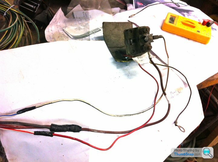
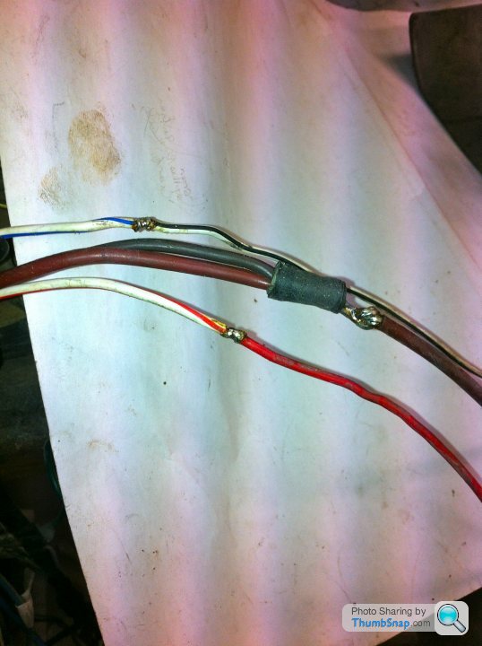
When checking the wiring from the starter solenoid I lost my way.
I missed a brown thick wire and a red/bleu wire. (see pics)
I took the insulation tape from the cable loom and found out what had been altered.
One of the owners had lengthen the wires with a red wire and didn't use the black earthing cable. The latest he solved by an earthing cable from the solenoid to the chassis.
All connects soldered so no problem (see pics).
Now I want to know what te correct position of the starter solenoid is for the Vixen S3?
Any suggestions?
Hans

The only comment I would chip in with, based on my own Vixen experiences is that if you going down the route of installing a tuned crossflow, the standard starter motor barely turns the engine over. I had to fit a high torque starter motor which came with a built in solenoid. Worth thinking about before you proceed with any more wiring.
Grantura MKI said:
Looking excellent! Hope Phil was well fed and watered this time?
Best,
D.
Mmmm... Nice brie Best,
D.

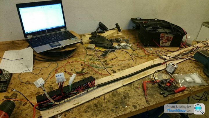
Car coming along, need to get the fuse box into the car next session so we can start commissioning it circuit by circuit. I can only think one wire at a time!
It will look a bit neater when the wires are bound into the looms (l hope).
P.
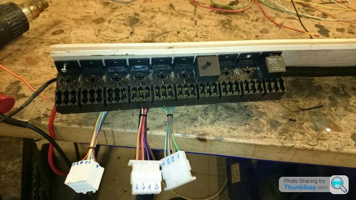
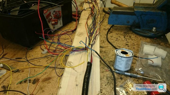
WIP 10 relay's 23 fuses in use. This is the "backbone" with the relay's placed in the passenger footwell, 3 connectors for the front light, engine components power and the ECU. On the other end will be connectors for the switch board, instrument panel, rear end and steering wheel.
Spiral wrap is a quite good solution when you forget a wire or two :-)
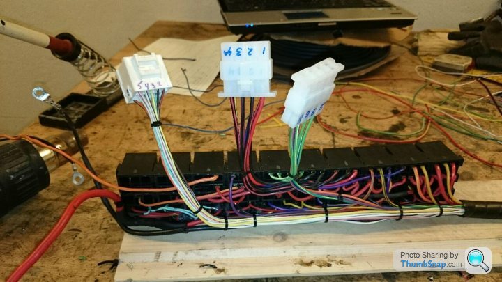
Spiral wrap is a quite good solution when you forget a wire or two :-)
Hi Andrew
Main reason for my rewiring is to ensure that a single failure will not make the car stall in the middle of a race, and in case, make trouble shooting much faster. So more or less all consumers will get their own fuse. And I was considering if I could eliminate single point of failure on the most critical things like ignition and injectors. But it was getting a little to "avionics" like :-) and anyway are the ECU potentially the weakest link.
And with that boring a F1 GP, did I make a lot of progress this evening.
Hi Andrew and other electricians.
Some question based on what I see and read in this forum.
Where is the inertia switch for?
Why not using earthing blocks in stead of extra points through the firewall as done by A. ?
And do you connect the bolts on the engine side to the frame? Extra connections give more chance for failure I was told.
When you use more fuses you also need more wiring with E=power. The ignition gives only 3 or 4 wires with power after turning the key. So where do you take the extra wires from?
Sounds as a stupid question but not for me.
Because splitting up those 4 wires to 10 or more can cause overheated wires (or not???)
Hans
Hi Hans
A picture of my diagram (not that good as Jpeg) ...
And 2 things... for the power distribution, do I have main relays that are controlled from the ignition key, so only 20mA throu the key. Other power consumers are allso relay controlled, 10 in total, so there are only a few switches that directly switch on current.
And the main issue is current, the higher current the thicker cables, in order to avoid voltage drop over the wires.
For the ground thing... if you run without microprocessors (ECU) are there not many topics (except radio noise) and focus can be on current draw, all the current from the + wires need to go back throu ground to the alternator. But if you have a microprocessor in the car, and thereby many low current sensors as well, are "ground loop noise" like black magic. If the ground have loops then will there be a lot of harmonic noise on the ground, and with a frame like the TVR's are there many loops for the ground noise. Best solution is to avoid using the frame as ground plane, and solely use the engine for that purpose. And ground need to be distributed like a tree, with the engine beeing the root. and ideally should all ground be connected in a single point. But again, this apply mainly for sensors and the ECU. A normal bulb wont care the electronic ac noise.
Complicated stuff, and for a old school car, don't care. The power distribution with many relay's and using the switches for low current control of the relay's is the main topic for making a trouble free instalation, and yes, the power wire from the battery/generator need to be 10mm2 or more.
Edited by madsvlund on Monday 3rd November 18:30
Gassing Station | TVR Classics | Top of Page | What's New | My Stuff