Vixen 302 V8 Tweety
Discussion


ephemera said:
Hi Neil, interesting thoughts, thank you!
I considered using the leading edge bonnet vents for intake purposes, but I decided having maximum heat release when entering low speed heavy traffic is more important in my road application. Also filtering that air is difficult due to the space constraint. Last reason was that I don't like to have an air connection between the fixed location airbox and a bonnet which can open, it will be very hard to seal properly. The air coming from the front of the car is luckily also dense in that area, and allows me to use two large air filters behind the indicator area which can be fixed to the chassis, so stable and independent from an opening bonnet.
Could you elaborate why the airbox should not be fully sealed in your opinion? I would think that is precisely the purpose of it? Making sure only cool and filtered air comes in the engine? Possible back fires are hopefully taken care of by the two air intakes.
Opening the airbox upper side and sealing it with a rubber seal against the bonnet would be difficult for me to achieve, there is a relative movement between the two, and wear particles from rubber and bonnet inner surface should not be allowed in the engine. The extra volume created is minimal, the airbox is a few mm from the bonnet as it is.
But I am always willing to learn, so any thoughts are very appreciated!
The race car solution is to have a hole in the top of the bonnet, minimal filtration and a seal along an open side airbox. I don't know how they cope with rain, though ;-)
But proof and pudding, testing and measuring etc ;-) Will keep you all posted.
Hi Ephemera. The way I would do it would be to open up the rear of the box as discussed to allow air to enter via the rear vent position. I would also remove top panel but I would extend the sides of the plenum and shape the side profiles of the Lexan so that they mirror the internal bonnet profile, allow a bit of a gap for relative movement, then utilise something like a door or boot seal to take up the gap and create the sealed plenum you are after... I think the existing 2 inlets you have will just not be enough for the air requirements that the 8 chokes will need but you will find that out via the rolling road I considered using the leading edge bonnet vents for intake purposes, but I decided having maximum heat release when entering low speed heavy traffic is more important in my road application. Also filtering that air is difficult due to the space constraint. Last reason was that I don't like to have an air connection between the fixed location airbox and a bonnet which can open, it will be very hard to seal properly. The air coming from the front of the car is luckily also dense in that area, and allows me to use two large air filters behind the indicator area which can be fixed to the chassis, so stable and independent from an opening bonnet.
Could you elaborate why the airbox should not be fully sealed in your opinion? I would think that is precisely the purpose of it? Making sure only cool and filtered air comes in the engine? Possible back fires are hopefully taken care of by the two air intakes.
Opening the airbox upper side and sealing it with a rubber seal against the bonnet would be difficult for me to achieve, there is a relative movement between the two, and wear particles from rubber and bonnet inner surface should not be allowed in the engine. The extra volume created is minimal, the airbox is a few mm from the bonnet as it is.
But I am always willing to learn, so any thoughts are very appreciated!
The race car solution is to have a hole in the top of the bonnet, minimal filtration and a seal along an open side airbox. I don't know how they cope with rain, though ;-)
But proof and pudding, testing and measuring etc ;-) Will keep you all posted.
Edited by ephemera on Saturday 20th October 15:22
 Its all looking very good though
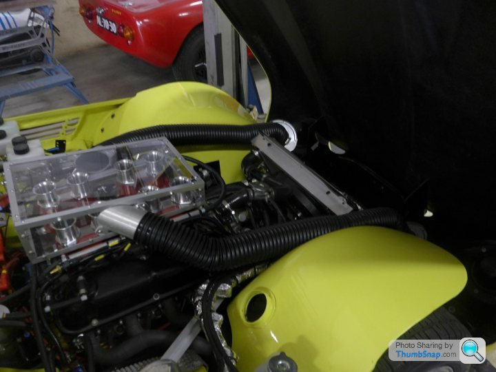

I suspect your air box is blocking most of the air outflow, from the raised portion, of the middle of the bonnet.
As for the other part, the two cold air pipes probably are sufficient. I am guessing the pipes are. If you have any concerns about the air cleaners, you should be able to get a rating, from the manufacturer.
You can look at what cross sectional opening you have, at the smallest juncture, at both inlets, and compare that to the single or dual throttle bodies people are using/selling. From memory, a single 85mm will feed well over 400hp.
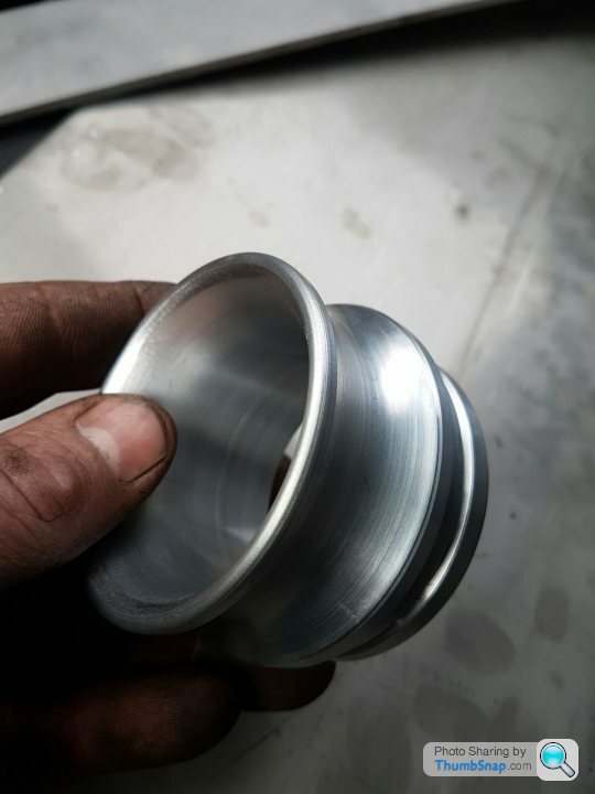
One thing you should be aware of: during my discussions with someone in the industry, whose opinion I greatly respect, I learned, that one place to reduce losses, is at the bellmouth. He kept driving home the point, that the optimum solution was a full radius bellmouth, and everything else was a compromise.
Best,
Bernard.
As for the other part, the two cold air pipes probably are sufficient. I am guessing the pipes are. If you have any concerns about the air cleaners, you should be able to get a rating, from the manufacturer.
You can look at what cross sectional opening you have, at the smallest juncture, at both inlets, and compare that to the single or dual throttle bodies people are using/selling. From memory, a single 85mm will feed well over 400hp.
One thing you should be aware of: during my discussions with someone in the industry, whose opinion I greatly respect, I learned, that one place to reduce losses, is at the bellmouth. He kept driving home the point, that the optimum solution was a full radius bellmouth, and everything else was a compromise.
Best,
Bernard.
Bernard, thanks for the interesting points you raised, in this way a thread like this is getting greater and greater for people doing these kind of things.
Heat release: good point, I tried to keep the length of the airbox limited so the air vents are still as open as possible. My train of thought was that in heavy traffic the hot air will ascend to the highest point under the bonnet and if there are holes at that location it will find its way out. It will be way better than nothing, and also better than gulping that hot air into the engine again. But I will test and report back!
By the way, in the latest Practical Performance car magazine Dave Walker of Emerald wrote an article stating 10 degr intake temperature difference equals around 3% power difference. I think our under bonnet temperatures can easily reach 50 degr and beyond, compared to say 20 degr outside. Of course you need to insulate your air supply to profit from that, but that is an additional advantage of polycarbonate compared to say aluminium.
The full radius bell mouth shape you mentioned: yes, this is correct. I have at the moment an intermediate radius shape for the short trumpets, and a three quarter radius for the long trumpets. But good shout, I will try to borrow full radius trumpets on the dyno day and compare. Place your bets1 I think the (lack of) free area above and around the mouths will play a significant role.
Intake cross section air hoses/filters: I have two hoses with 75mm internal diameter, so total cross section of 8831 mm^2. As you said, a single throttle body plus intake hose of say an LS is 85 mm or smaller, so 5672 mm^2. Also, when one looks at the intake hoses of a nineties Griffith 500, a V8 Cerbera and the 2020 Griffith, I am not too concerned in that area.
In the end, life is full of compromises, hot/cold air inlet temperatures, withstand heavy traffic real life conditions, filtering air for engine protection, trumpet length for torque/power compromises, looks (let's be honest), costs, etc... but I love to test and conclude based on science and hard data. All remarks are welcome during the journey though ;-)
I would love to make an actuated continuously variable length trumpet system one day, but the downdrafts on this project don't have the space for that.
www.turbosport.co.uk/showthread.php?t=455891
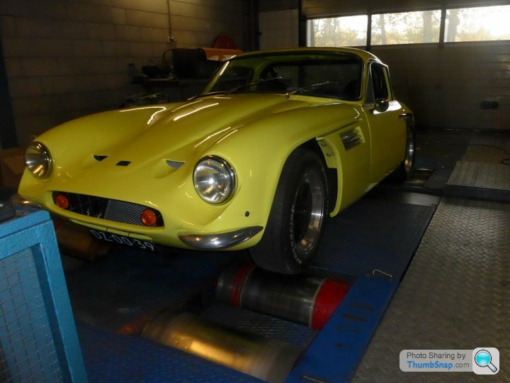
Dyno update, with video's:
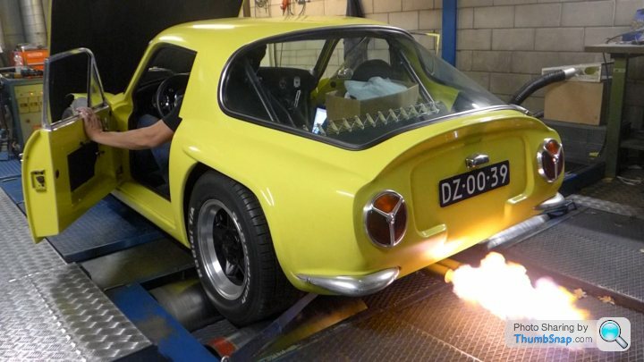
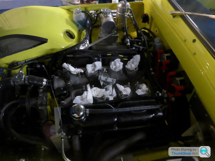
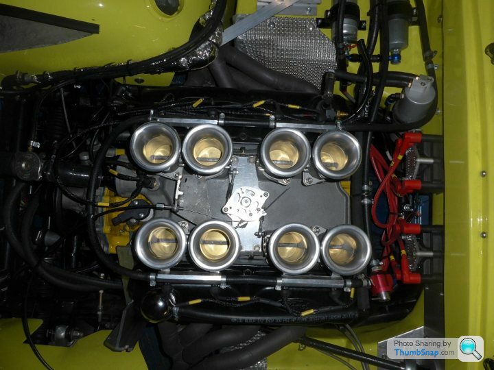
The chassis dyno days the past week were interesting. To cut a long story short, The inlet manifold was a ported one (48 mm ports), the linkage system was not really suitable for very fine adjustment, so I decided to bite the bullet and remove the current 45mm VGS ITB set up and replace it with a 50mm KMS set up with new throttle and synchronization linkage system. The car was strapped down this time and the only problem was a slight oil leak from the oil dipstick tube where it was pushed into the engine block, need to address that. But fortunately we could do some dyno runs and in the end I am very happy, the driveability is beyond expectations, and the performance very healthy. Here are some video's and photos:
https://vimeo.com/299525289
https://vimeo.com/299525901
Edited by ephemera on Wednesday 7th November 22:02


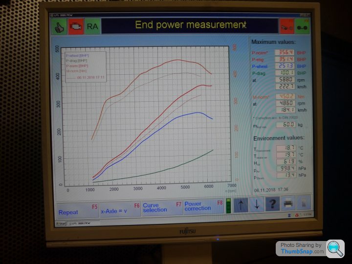
Hi Neil, the numbers mentioned are at the flywheel. And yes, I promised to address the airbox question. After talking to the experienced people at KMS, they agreed with the general principle of the current airbox, so front intake (unless I wanted to cut the bonnet and fit a scoop ala AC Cobra). But unfortunately the new ITB set up means the current airbox cannot be used anymore. Full radius trumpets: yes, done. They stressed that for these types of engines, the best thing to do is to increase the inlet lengths as much as possible, preferably to more than 300mm (see e.g. BMW M5). This means in my installation a 90 degree bend per runner and using two side mounted airboxes, similar to a V8 Cerbera. So my plan is to experiment with that in the future.
Edited by ephemera on Thursday 8th November 07:05
great to see and hear, I think it makes some sound :-)
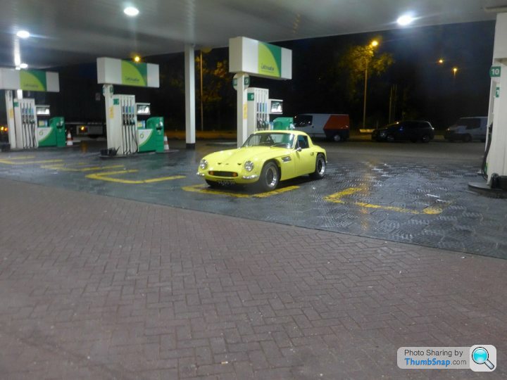
also, is that enough light in the dark? looks a bit poor/yellow-ish?
is that 251hp at the wheels? sounds like fun, did you had the car weighted? curious what such Vixen does, 900+?
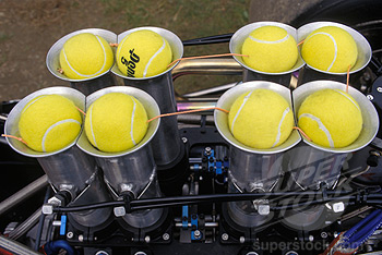
ow, I also got such sort kelks in my car, different car though, but also 8 :-) and after that,
they made a box around it and closed them up.
also, is that enough light in the dark? looks a bit poor/yellow-ish?
is that 251hp at the wheels? sounds like fun, did you had the car weighted? curious what such Vixen does, 900+?
ow, I also got such sort kelks in my car, different car though, but also 8 :-) and after that,
they made a box around it and closed them up.
Gassing Station | TVR Classics | Top of Page | What's New | My Stuff