Attempting to build the fastest road legal Elan in the world
Discussion


Carbon exhaust heat shields finally complete, apart from some beautification and drilling fastening holes. Final weight is 936gms compared to the aluminium originals at 2202gms, a 1266gm saving. May not sound much for all the work, but it is a 57% reduction :-)
Also shown are the underfloor aero strakes. These weigh in at a total 377gms, which is 63gms/m. When trimmed that will come down to around 50gms/m. Not exactly heavy :-) They will serve two jobs, directing underfloor air flow and stiffening the undertrays, allowing them to be thinner and lighter.
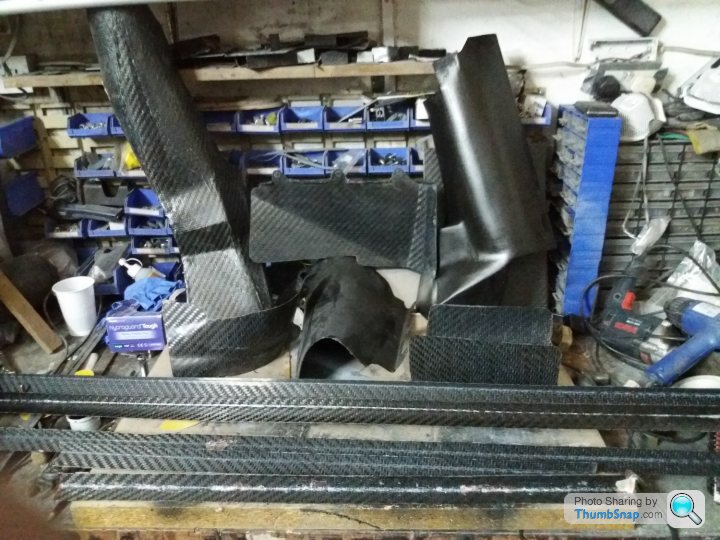
Also shown are the underfloor aero strakes. These weigh in at a total 377gms, which is 63gms/m. When trimmed that will come down to around 50gms/m. Not exactly heavy :-) They will serve two jobs, directing underfloor air flow and stiffening the undertrays, allowing them to be thinner and lighter.
Edited by stevebroad on Friday 26th October 18:11
ReaperCushions said:
I wonder if Horatio Pagani uses house bricks in his carbon fibre production process? 
Love this thread, so talented and you can really see your skills (especially in the CF making) come on leaps and bounds. Amazing.
House brick/CF combination is a patented process and I would require royalty payments if he does :-)Love this thread, so talented and you can really see your skills (especially in the CF making) come on leaps and bounds. Amazing.
Thanks, although a skilled CF practitioner would weep if he saw my work conditions, methods and finished results close up. Luckily I am hiding my carbon so the imperfections are disguised :-)
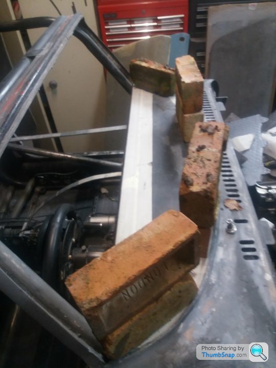
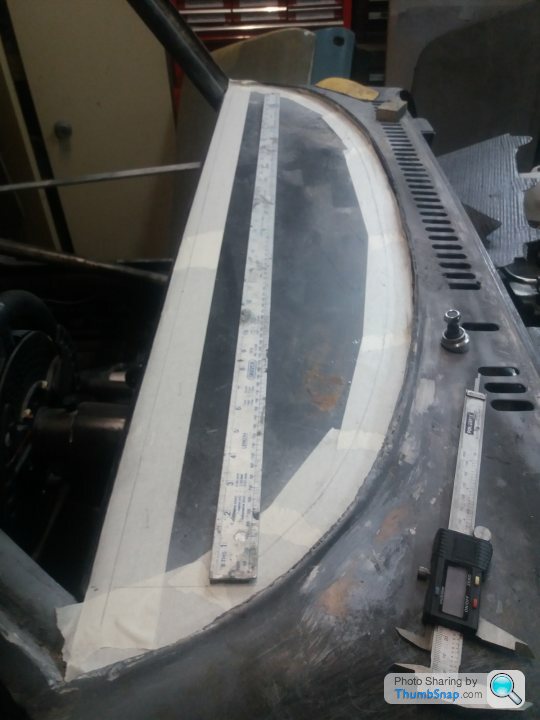
If there is anyone out there that isn't convinced that I am obsessed with weight loss, then this should convince them once and for all :-)
I need an interior mirror to comply with the MOT, so I decided to make one.
Took the mirror out of my wife's old Astra that is still in the paddock (she can't bear to get rid of it!) and removed the arm and ball joint. However, it weighed a mighty 101gms so it had to be lightened and it ended up at 51gms.
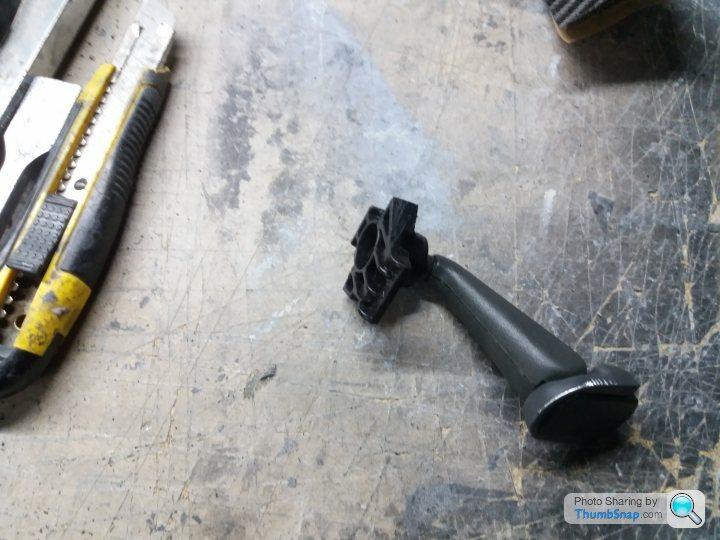
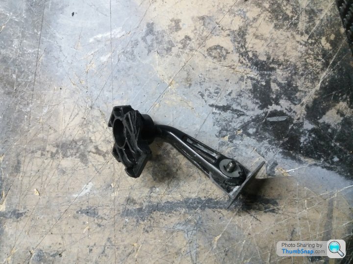
Next task was to make the mirror holder.
Made the mould out of aluminium and put a slight curve into it so it would stabilise the thin carbon and give a wider field of view allowing the mirror to be smaller.

Experimented with 2 and 3 layers of CF and settled on 2.
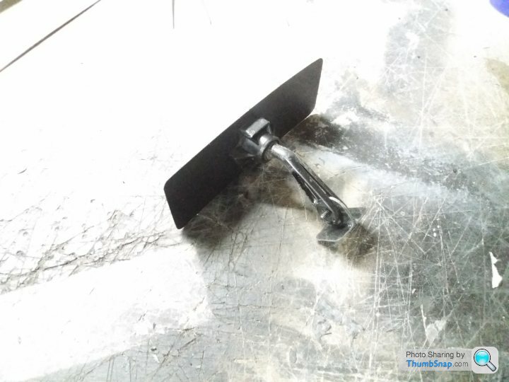
Although I am waiting for the stick on 0.2mm thick plastic mirror tiles, it shouldn't end up weighing much more than the just under 58gms it is at the moment :-)
I need an interior mirror to comply with the MOT, so I decided to make one.
Took the mirror out of my wife's old Astra that is still in the paddock (she can't bear to get rid of it!) and removed the arm and ball joint. However, it weighed a mighty 101gms so it had to be lightened and it ended up at 51gms.
Next task was to make the mirror holder.
Made the mould out of aluminium and put a slight curve into it so it would stabilise the thin carbon and give a wider field of view allowing the mirror to be smaller.
Experimented with 2 and 3 layers of CF and settled on 2.
Although I am waiting for the stick on 0.2mm thick plastic mirror tiles, it shouldn't end up weighing much more than the just under 58gms it is at the moment :-)
Back to the wiper motor saga.
A friend sent me a (I assume) Volvo headlamp wiper motor to experiment with. The weight, at around 230gms, was good and fitting wouldn't be a problem as I could utilise the existing bracket.
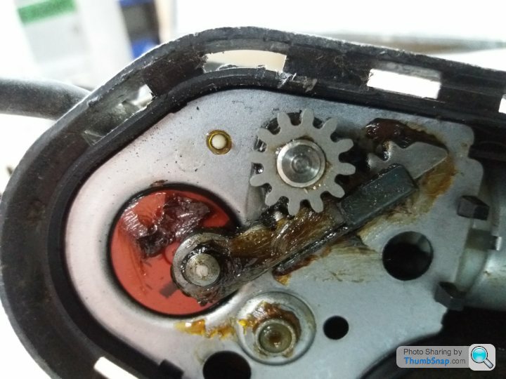
However, it sweeps just under 90 degrees which isn't enough to clear the required area of screen. On taking the back off the simple oscillating mechanism was revealed. I contemplated making a new cog with less teeth (the straight section is sprung loaded so a smaller cog would fit) which would increase the arc angle but I think that the blade would be moving too fast.
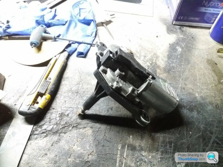
So I looked at rear screen wipers and came across a used Fiat Punto motor for £8 inc postage on eBay which I bought. It weighs 810gms, almost 500gms more than the headlamp unit but over 1.5kg less than the OEM unit. The great thing about rear screen wipers is their swept arc, which in this case is just under 180 degrees.
Thanks, Colin, for you contribution, It helped to clarify what I needed.
There are small, dedicated units available for hot rods, but they have integrated switches which won't work for me.
Unless I can find a lighter rear wiper I will go with this one.
A friend sent me a (I assume) Volvo headlamp wiper motor to experiment with. The weight, at around 230gms, was good and fitting wouldn't be a problem as I could utilise the existing bracket.
However, it sweeps just under 90 degrees which isn't enough to clear the required area of screen. On taking the back off the simple oscillating mechanism was revealed. I contemplated making a new cog with less teeth (the straight section is sprung loaded so a smaller cog would fit) which would increase the arc angle but I think that the blade would be moving too fast.
So I looked at rear screen wipers and came across a used Fiat Punto motor for £8 inc postage on eBay which I bought. It weighs 810gms, almost 500gms more than the headlamp unit but over 1.5kg less than the OEM unit. The great thing about rear screen wipers is their swept arc, which in this case is just under 180 degrees.
Thanks, Colin, for you contribution, It helped to clarify what I needed.
There are small, dedicated units available for hot rods, but they have integrated switches which won't work for me.
Unless I can find a lighter rear wiper I will go with this one.
Edited by stevebroad on Sunday 28th October 17:11
I think that I have finalised the location of the wiper motor, just need to make some brackets. Found an M16 die that fitted nicely over the spindle cover so I was able to cut a thread into it. Rummaging through my box of old nuts I found a couple of M16 nuts with the same pitch (that's why you should never throw stuff away :-) ) They were locking nuts so I attacked then with the lathe. I now need to make a couple of angled collars to hold the wiper at the correct angle.

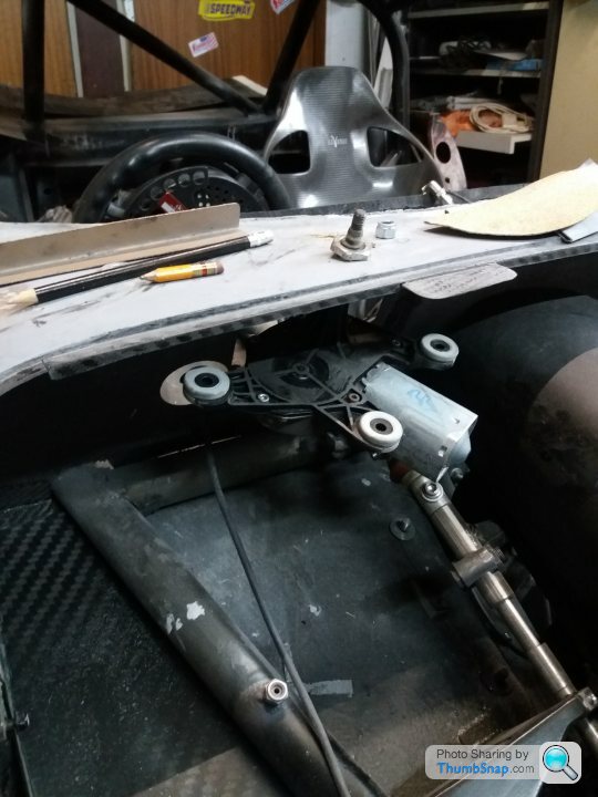
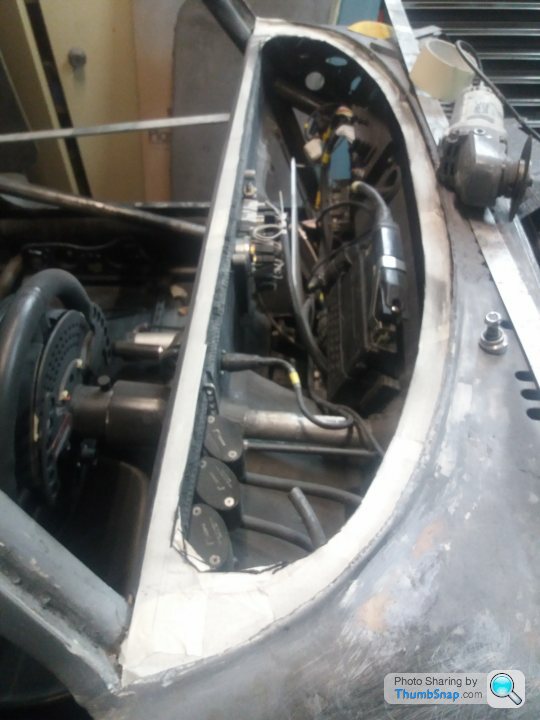
I have had to cut a section of bulkhead out to accommodate the motor but that is small beer to fix as I have a piece of carbon in my scrap bin that is the perfect shape.

You can see where I have attacked the motor with abrasives, removing 15gms, not really worth the effort but I had to do it :-) I will tidy it up prior to fitting.
I have made a couple of rough and ready brackets to secure the motor.

I have had to cut a section of bulkhead out to accommodate the motor but that is small beer to fix as I have a piece of carbon in my scrap bin that is the perfect shape.
You can see where I have attacked the motor with abrasives, removing 15gms, not really worth the effort but I had to do it :-) I will tidy it up prior to fitting.
I have made a couple of rough and ready brackets to secure the motor.
Edited by stevebroad on Monday 29th October 09:45
Edited by stevebroad on Monday 29th October 09:46
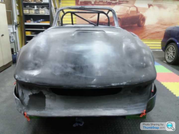
I finally started a task today that I have been putting off for months - Fitting the dash top. I have been prevaricating and ruminating for some time as I couldn't decide on the best way to do it.
Initially I was going to simply stick it on and access the electrics through the central switch panel and the glove box cover. However, as the stuff behind the dash became more complicated and numerous it became obvious that I would need to retrain as a gynaecologist in order to be able to work on everything.
So, I decided that part of the dash top had to be removable to allow decent access, but how to do this without it looking rubbish?
I have yet to finalise how the removable cover is going to be secured but at least I have made a start and this is usually the most difficult part of any project.
Bought a tripod for the phone so decided to try it out. Hadn't planned to post this but I then thought, why the hell not?
https://www.youtube.com/watch?v=LcoAQXZ1y2s
https://www.youtube.com/watch?v=LcoAQXZ1y2s


It has been a while since my last confession, I mean post.
Basically a lot of fettling of bodywork, so nothing much to report on that front. However, I have been looking at fitting air curtains:
And started on side splitters and skirts:
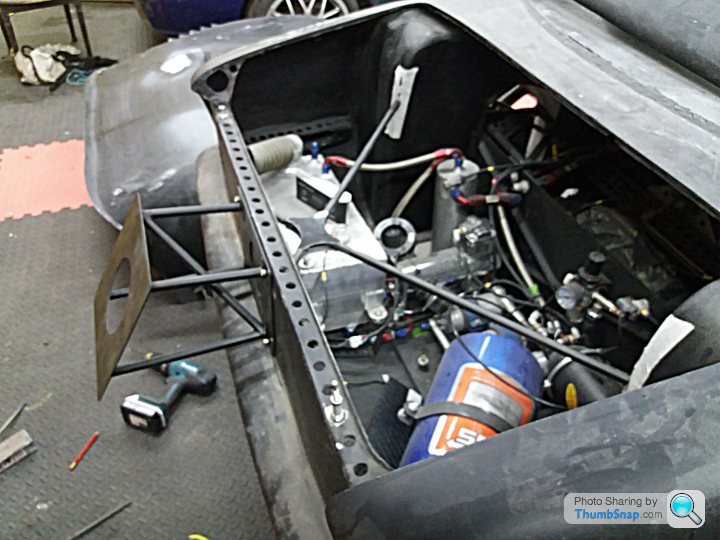
And sorting out parachute support frame and chassis bracket:

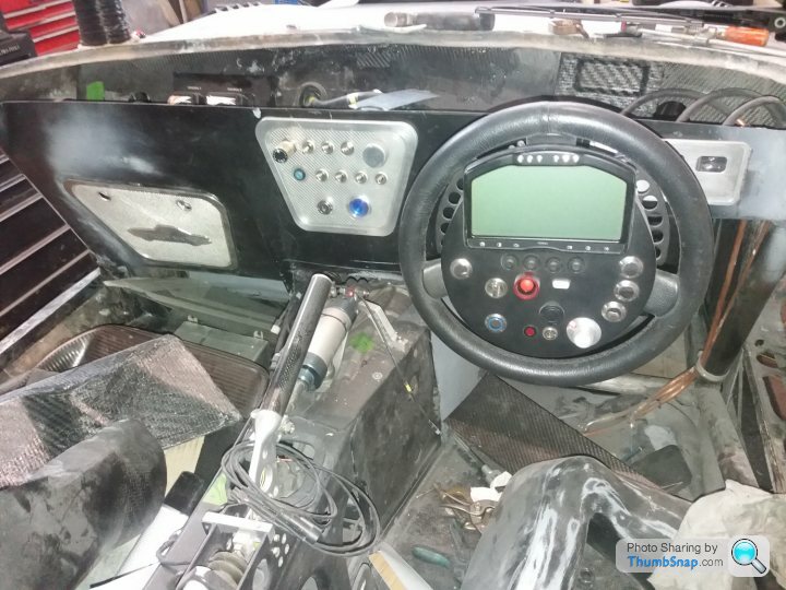
Finished steering wheel (the flappy paddles are hidden behind the switch panel0;

Dash layout finalised. The windowed panel behind the steering wheel houses the brake and clutch fluid reservoirs. It swings out into the cockpit area for ease of access;
Induction pipework finished;
Basically a lot of fettling of bodywork, so nothing much to report on that front. However, I have been looking at fitting air curtains:
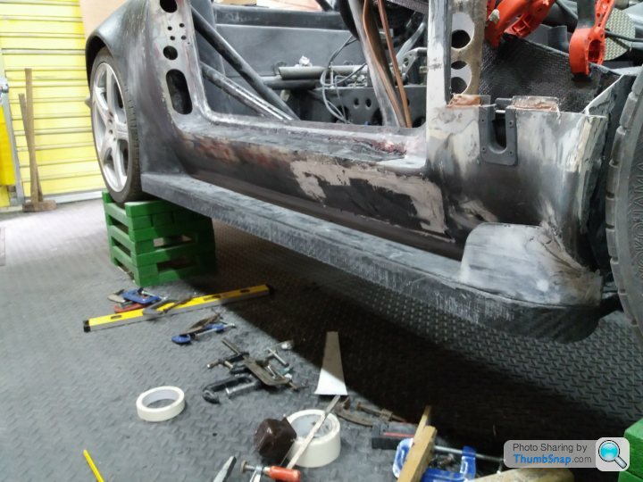
And started on side splitters and skirts:
And sorting out parachute support frame and chassis bracket:
Finished steering wheel (the flappy paddles are hidden behind the switch panel0;
Dash layout finalised. The windowed panel behind the steering wheel houses the brake and clutch fluid reservoirs. It swings out into the cockpit area for ease of access;
Induction pipework finished;
Edited by stevebroad on Saturday 16th November 16:22
trails said:
More photos of the assembled car please 
Not sure where to start, but here goes :-) Some of these may well appear earlier in this thread.Car in it's nice new garage.

Basic engine set up. Throttle body is now DBW.

Front suspension. Adjustable in both camber and caster in-situ, no dismantling required.

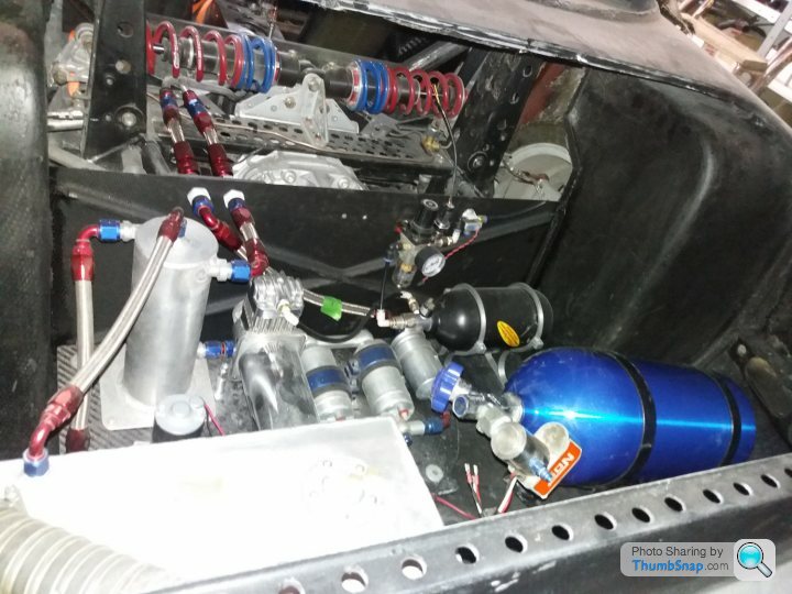
Rear suspension. inboard dampers, allowing for wider wheels (11"+). Camber and toe in/out adjustable. Compressed air reservoir now moved into boot.

Fuel system:
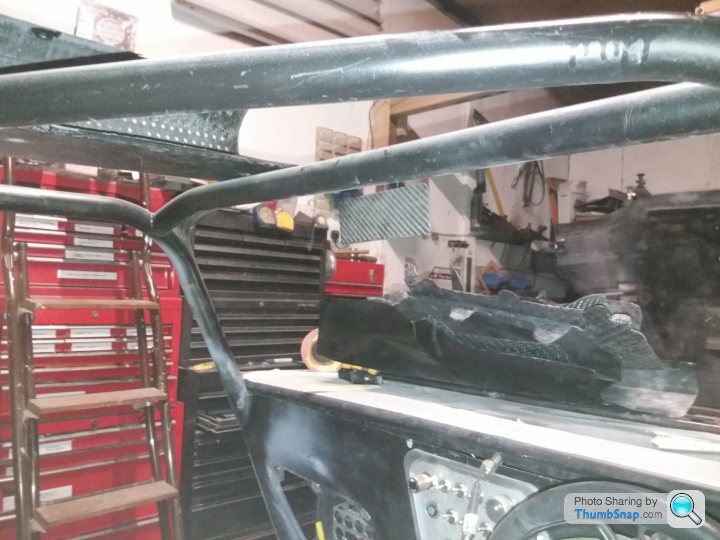
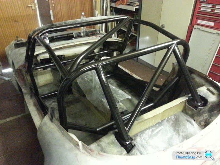
Roll cage. There is now a bar between the two suspension uprights. This photo is pre carbon fibre flip front.
If there is anything in particular that you want to see, let me know :-)

Gassing Station | Readers' Cars | Top of Page | What's New | My Stuff