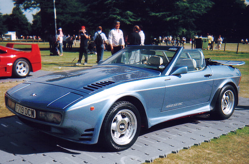
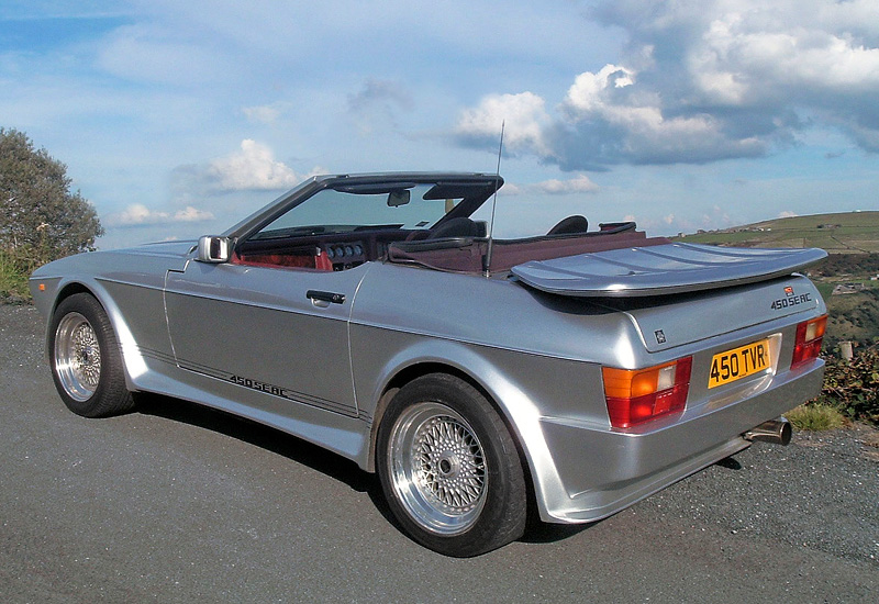
Kelvinators TVR Tasmin
Discussion


Still need to replace the brake rotors, as they aren't running true, so I'll probably make a start on them with the front pair this weekend. I also need to decide if I pull up and replace the carpet before the British Car Day show at the start of Feb, or after it. Somewhere between that, I need to give the car its first wash since I got it, and machine polish and wax the paint as its looking a bit dull (and filthy) and I want it to look great at the show.
Well, it has been an interesting time on the TVR front. Most recently, I have been dealing with one of those "why did I start this" jobs on the car.
One of the first things I did after failing the WOF inspection was to order some new tyres. The old tyres, although both a good brand (Dunlop) and near new tread, were as hard as rocks, slippery as anything, starting to crack, the wrong size, and were flat-spotted. Its no surprise really, they were about 10 years old.
The spare was even worse, I suspect it may have been from 1986, as its a long-obsolete model (Good Year Eagle NCT 60, the original spec tyre for the TVR), the rubber felt like plastic, and the date stamp was 196 without an arrow (the arrow indicates it's from the 90s, and a three-digit number indicates its pre-2000).


They got their monies worth out of this one!

After much deliberation, I decided to revert back to the standard size all around, at a "low profile" 205/60R14. The old rears were 215/65R14, so not only wider but also a lot taller (about 16mm taller than standard). This always looked a bit wrong to me; too much sidewall.

I don't know if the reason for the size change was just because of what was on hand, or if there was a deliberate choice to do it, but Its not my thing. I did have some issue getting the original size; there wasn't a lot of options for brands, but I chose to go with a tyre that's a decent economy tyre. No, it's not as good as a performance tyre, but options were limited, as was my budget, and at the price I got these for it was hard to say no. A decent new economy tyre is better than any old, hard, performance tyre.
The tyre I chose was a Nexen CP672. It has good reviews, is a modern Korean made tyre, and Nexen is OEM fit on some Hyundai and Kia cars, so it can't be all bad. At least it's not a Chinese ditch-finder.

Hover car, again

The Saab came in handy for taking it all down to the tyre shop for fitting. The Honda probably could've managed, but the Saab just ate it all up with space to spare.

With the new tyres fitted, it was time to tackle the reason I failed the WOF. The front lower ball joints.
It turns out these are the original 40 year old ball joints, as they are riveted to the arms. The replacements all have bolts holding them in. Not great news, they're a prick to get out.

I struggled around a bit on the first one, but worked out some tips that made the second a lot quicker and easier.
First, this job sucks. It's messy, it's hard to access, and takes more than your usual spanner set to do.
The split pin in the nut was my first issue. It was old and properly rusted into the hole. After a lot of faffing about trying to hammer it out with a punch, and then trying to smash it up with a chisel, the easiest way for me to remove it wasn't to remove it at all, but to chop the tails off, slip a spanner on the nut and swing off it until the nut cut through the split pin. You can see the split pin remains still in the hole, about halfway down the thread. Both the nut, and the joint are junk, so not an issue.

Now, if you have a ball joint splitter, go ahead and use it to split the ball joint, otherwise use the BFH and hit the knuckle with a few sharp hits, and the taper should pop. I found jacking the hub up helps to put pressure on the taper and make it easier to pop.

You can see in the above photo I have removed the two bolts from the tie bar. This wasn't smart, it was a real pain to line it back up again, what I did on the second one was to use a clamp and hold the bar into place on the arm, and leaving the nut-less bolts in the holes to align it

Next, undo the nut off the tie rod end and release the taper. Move the tie rod out of the way. Now for the fun part, grab your grinder, and grind the top of the rivets down so they are as low as possible, and flat.

Use a punch to mark the center of the rivet, and using plenty of cutting oil, starting with a small drill bit, drill through the rivet. Work your way up to a larger bit. After a couple of different sizes I changed to a step drill. Take care not to enlarge the hole in the arm.

The goal is to cut the head off the rivet, so you can get a chisel in and split the parts

Once you do both of the rivets, push the ball joint through the arm and that's part one done.

The new ones should come with a pair of nuts and bolts to replace the rivets, as well as a grease nipple. Fit the nipple, and pump the joint full of grease


Now refit the new joint from the underside of the arm. Make sure everything lines up, and leave all the bolts loose until everything is aligned and in place. Once all the bolts are in, tighten them all up. The two large nuts want to be 58-68NM, whilst the little ones don't have a torque setting, so just do them up tight.
Now for another fun part, getting the hub back onto the taper. I found this to be too much of an arm-full, so used a jack between the two arms to lift the upper arm and lower the knuckle over the stud. Not a Ford/TVR approved method, I'm sure, but it worked well.

And then you refit the nut. The Nylock was a pain to fit as until it cut through the nylon it kept trying to spin the balljoint, but I got there in the end. There is a torque setting, but I couldn't get a torque wrench in there, so settled for bloody tight with a spanner.

With both sides done, on went the wheels with new tyres, and it was time for a shakedown.
The front end feels a bit tighter, but the biggest difference are the new tyres, which don't try and kill you when you point the car at a corner, and the rear shocks (new damper adjustable replacements also went in as I felt the old ones were a bit soft) control the rear end better. The incorrectly high (40psi) tyre pressure resulted in a nice light steering, but a harsher ride and less grip than when the pressure was lowered to the correct 24psi. I think this car has the heaviest steering of any car I have driven.
I could help but take some photos. It's a great looking little car, and such an experience to drive.


So, with new bits in, it was time for the WOF recheck. Almost 4 years since the last one expired, a new WOF!


Its a great feeling, knowing the car is finally good enough that its back on the road, when for the last few years it had been sitting at a workshop being ignored because the injection work was just "too hard". Sadly the injection work is just the tip of the iceberg of issues with this car, but I'm working through them. I do wish the seller, or (more importantly) the "specialist" were honest about the condition of the car. Some of these issues aren't new, and are hard to miss.
So with a new WOF, what's the first thing I do? Go out and enjoy the car right? Nah, that's not how I work.

It was time to take the car off the road again, and fix the brakes. I knew this job was going to be bad, but little did I know how bad it was about to get.
As I previously mentioned, the brakes had a shudder. This was also noted at the WOF, but wasn't enough to fail on, yet.
Unfortunately, I had had enough of the shudder. It was bad when braking from 100kph, and annoying coming to a stop, so had to be fixed.
I purchased a set of new rotors, front and rear, but just needed to fit them. I was originally going to start with the fronts, as they are a lot easier to access, but decided to do the hard ones first, and get it over and done with; the rears.
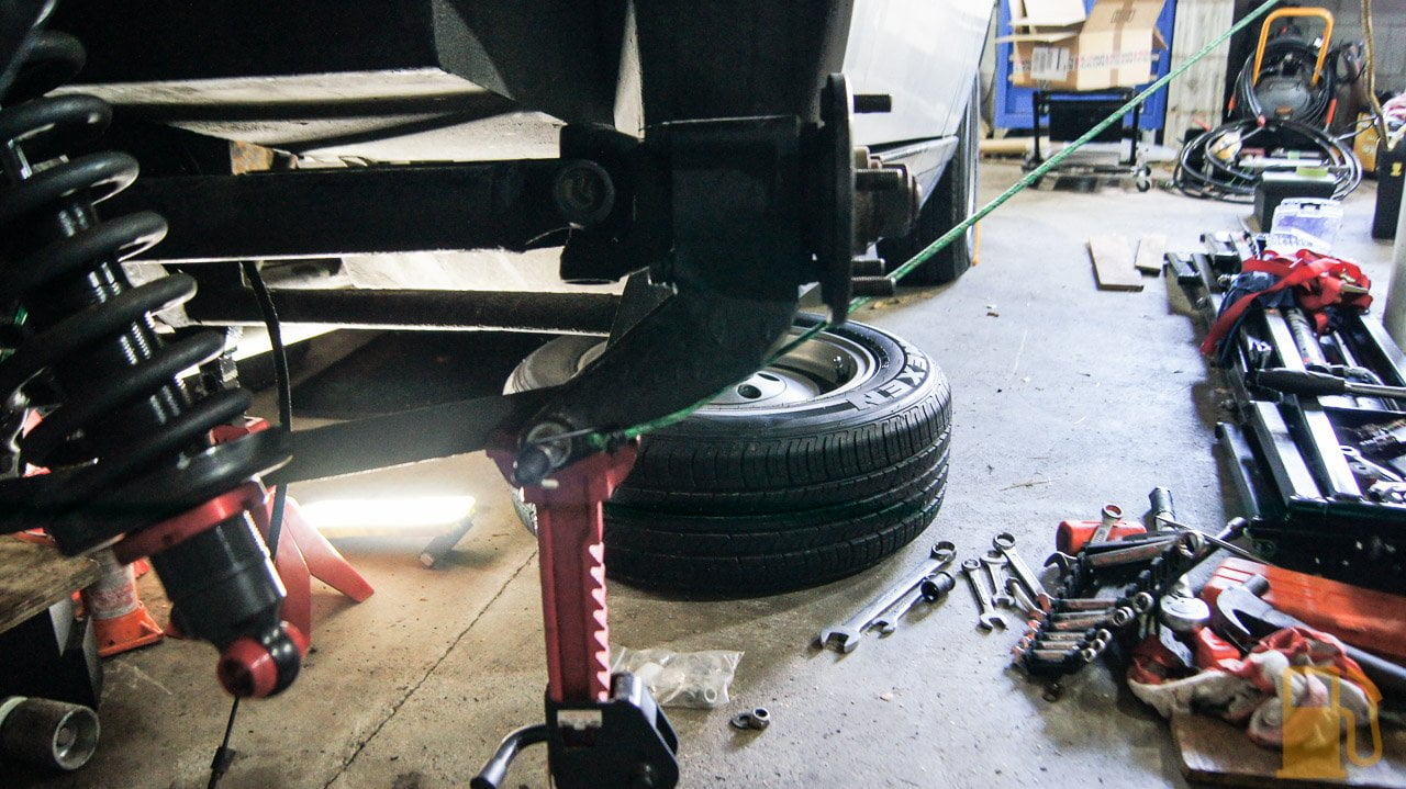
Of course because I have inboard rear brakes, nothing was going to be simple. I asked around and the general opinion was that it was easiest to drop the whole rear diff to get the calipers off, so the rotors could be removed. Yay.
Dropping the diff on a Wedge isn't too bad of a job, especially with the trailing arm models like mine, as there aren't a whole lot of things holding the assembly in. Unfortunately, we found the job was made much harder on my car thanks to whoever designed the exhaust, as there isn't quite enough space between the two exhaust pipes to slip the calipers down and out. After a heck of a lot of levering, and much help from my lovely apprentice, this happened

I'll tell you now, this thing is bloody heavy. We lowered it on the jack, and removed it from the jack to work on it. I'm not too sure how we will get it back on the jack to refit it, lots of brute force I guess.
With everything on the ground it was time to remove the calipers to extract the rotors. The handbrake calipers on the top need to go first. These are held in by two pins each. One side had nice (barely) greased and free pins, the other had dry, stuck, pins. Not ideal at all. They did come out in the end.

The hand brake pads looked OK. I have receipts for them being replaced a few years ago. The units need a good clean though.

Next, the calipers came off. These were missing the lock wire on the bolts.

and then the old rotors

You can see the extent of the runout in the wear on the rotor. Above the two arrows in rough and rusty, below them is shiny and smooth. The shiny spot is the high point, where the pads have been contacting well, and the rough part where the pads haven't been working as well.

I gave the shims a quick wire brush to get the obvious crud off them, and fit the new rotors. Here is an action shot; brushing so quick my arm is nothing but a blur

This is where it went all a little pear-shaped. I didn't check the runout on the new rotors before fitting the calipers, and when I did, it was worse than before I pulled the lot out. Previously on the old rotors, I had about 0.35mm runout. Now I had over 0.60mm runout. Crap.

At this point, I flipped tables and gave up for the day.
Well, they looked nice anyway. Mmm Brembo.


Today I forced myself to go into the garage and see what I could work out. I knew the shims looked a bit average, so let's start there.
I pulled the shims off and had a look at what I had. It wasn't good. The shims are stuffed. Rusted, crusty, painted and missing bits.


And the flange didn't do much better. It had baked on crusty rust, and paint on it

I had to chip a few bits like this off with a chisel, and then I wire brushed thoroughly


I can still see some room for improvement there too, but its a lot better.
The first way to see where the runout is, is to remove all the shims and see if the rotor runs true when mounted directly to the flange. After cleaning the flange, I fit the rotor to it and checked runout. The old rotor makes a great mount for the dial indicator


Much better at 0.08mm. I think I can get it a little lower with some strategic scraping, but the spec is up to 0.10mm

That's a great success. I did the same to the other side too. The shims were worse here, and the flanges covered in old crusty rust


I cleaned these up and tested them. Boom, awesome. 0.035mm

So the take away from this is a few things. I need new shims. DONT paint faces of flanges or shims. ALWAYS use copper grease on shims to stop them sticking together and reduce corrosion. Oh, and the bolts that hold the diff to the cradle should be tight; someone previously missed that memo.
Now I need to source some new shims, and we should be good to refit. I measured the old ones, and will try to replicate the original stack, but I may need to tweak it myself as I don't know if these are right or not.

One of the first things I did after failing the WOF inspection was to order some new tyres. The old tyres, although both a good brand (Dunlop) and near new tread, were as hard as rocks, slippery as anything, starting to crack, the wrong size, and were flat-spotted. Its no surprise really, they were about 10 years old.
The spare was even worse, I suspect it may have been from 1986, as its a long-obsolete model (Good Year Eagle NCT 60, the original spec tyre for the TVR), the rubber felt like plastic, and the date stamp was 196 without an arrow (the arrow indicates it's from the 90s, and a three-digit number indicates its pre-2000).


They got their monies worth out of this one!

After much deliberation, I decided to revert back to the standard size all around, at a "low profile" 205/60R14. The old rears were 215/65R14, so not only wider but also a lot taller (about 16mm taller than standard). This always looked a bit wrong to me; too much sidewall.

I don't know if the reason for the size change was just because of what was on hand, or if there was a deliberate choice to do it, but Its not my thing. I did have some issue getting the original size; there wasn't a lot of options for brands, but I chose to go with a tyre that's a decent economy tyre. No, it's not as good as a performance tyre, but options were limited, as was my budget, and at the price I got these for it was hard to say no. A decent new economy tyre is better than any old, hard, performance tyre.
The tyre I chose was a Nexen CP672. It has good reviews, is a modern Korean made tyre, and Nexen is OEM fit on some Hyundai and Kia cars, so it can't be all bad. At least it's not a Chinese ditch-finder.

Hover car, again

The Saab came in handy for taking it all down to the tyre shop for fitting. The Honda probably could've managed, but the Saab just ate it all up with space to spare.

With the new tyres fitted, it was time to tackle the reason I failed the WOF. The front lower ball joints.
It turns out these are the original 40 year old ball joints, as they are riveted to the arms. The replacements all have bolts holding them in. Not great news, they're a prick to get out.

I struggled around a bit on the first one, but worked out some tips that made the second a lot quicker and easier.
First, this job sucks. It's messy, it's hard to access, and takes more than your usual spanner set to do.
The split pin in the nut was my first issue. It was old and properly rusted into the hole. After a lot of faffing about trying to hammer it out with a punch, and then trying to smash it up with a chisel, the easiest way for me to remove it wasn't to remove it at all, but to chop the tails off, slip a spanner on the nut and swing off it until the nut cut through the split pin. You can see the split pin remains still in the hole, about halfway down the thread. Both the nut, and the joint are junk, so not an issue.

Now, if you have a ball joint splitter, go ahead and use it to split the ball joint, otherwise use the BFH and hit the knuckle with a few sharp hits, and the taper should pop. I found jacking the hub up helps to put pressure on the taper and make it easier to pop.

You can see in the above photo I have removed the two bolts from the tie bar. This wasn't smart, it was a real pain to line it back up again, what I did on the second one was to use a clamp and hold the bar into place on the arm, and leaving the nut-less bolts in the holes to align it

Next, undo the nut off the tie rod end and release the taper. Move the tie rod out of the way. Now for the fun part, grab your grinder, and grind the top of the rivets down so they are as low as possible, and flat.

Use a punch to mark the center of the rivet, and using plenty of cutting oil, starting with a small drill bit, drill through the rivet. Work your way up to a larger bit. After a couple of different sizes I changed to a step drill. Take care not to enlarge the hole in the arm.

The goal is to cut the head off the rivet, so you can get a chisel in and split the parts

Once you do both of the rivets, push the ball joint through the arm and that's part one done.

The new ones should come with a pair of nuts and bolts to replace the rivets, as well as a grease nipple. Fit the nipple, and pump the joint full of grease


Now refit the new joint from the underside of the arm. Make sure everything lines up, and leave all the bolts loose until everything is aligned and in place. Once all the bolts are in, tighten them all up. The two large nuts want to be 58-68NM, whilst the little ones don't have a torque setting, so just do them up tight.
Now for another fun part, getting the hub back onto the taper. I found this to be too much of an arm-full, so used a jack between the two arms to lift the upper arm and lower the knuckle over the stud. Not a Ford/TVR approved method, I'm sure, but it worked well.

And then you refit the nut. The Nylock was a pain to fit as until it cut through the nylon it kept trying to spin the balljoint, but I got there in the end. There is a torque setting, but I couldn't get a torque wrench in there, so settled for bloody tight with a spanner.

With both sides done, on went the wheels with new tyres, and it was time for a shakedown.
The front end feels a bit tighter, but the biggest difference are the new tyres, which don't try and kill you when you point the car at a corner, and the rear shocks (new damper adjustable replacements also went in as I felt the old ones were a bit soft) control the rear end better. The incorrectly high (40psi) tyre pressure resulted in a nice light steering, but a harsher ride and less grip than when the pressure was lowered to the correct 24psi. I think this car has the heaviest steering of any car I have driven.
I could help but take some photos. It's a great looking little car, and such an experience to drive.
So, with new bits in, it was time for the WOF recheck. Almost 4 years since the last one expired, a new WOF!


Its a great feeling, knowing the car is finally good enough that its back on the road, when for the last few years it had been sitting at a workshop being ignored because the injection work was just "too hard". Sadly the injection work is just the tip of the iceberg of issues with this car, but I'm working through them. I do wish the seller, or (more importantly) the "specialist" were honest about the condition of the car. Some of these issues aren't new, and are hard to miss.
So with a new WOF, what's the first thing I do? Go out and enjoy the car right? Nah, that's not how I work.
It was time to take the car off the road again, and fix the brakes. I knew this job was going to be bad, but little did I know how bad it was about to get.
As I previously mentioned, the brakes had a shudder. This was also noted at the WOF, but wasn't enough to fail on, yet.
Unfortunately, I had had enough of the shudder. It was bad when braking from 100kph, and annoying coming to a stop, so had to be fixed.
I purchased a set of new rotors, front and rear, but just needed to fit them. I was originally going to start with the fronts, as they are a lot easier to access, but decided to do the hard ones first, and get it over and done with; the rears.
Of course because I have inboard rear brakes, nothing was going to be simple. I asked around and the general opinion was that it was easiest to drop the whole rear diff to get the calipers off, so the rotors could be removed. Yay.
Dropping the diff on a Wedge isn't too bad of a job, especially with the trailing arm models like mine, as there aren't a whole lot of things holding the assembly in. Unfortunately, we found the job was made much harder on my car thanks to whoever designed the exhaust, as there isn't quite enough space between the two exhaust pipes to slip the calipers down and out. After a heck of a lot of levering, and much help from my lovely apprentice, this happened

I'll tell you now, this thing is bloody heavy. We lowered it on the jack, and removed it from the jack to work on it. I'm not too sure how we will get it back on the jack to refit it, lots of brute force I guess.
With everything on the ground it was time to remove the calipers to extract the rotors. The handbrake calipers on the top need to go first. These are held in by two pins each. One side had nice (barely) greased and free pins, the other had dry, stuck, pins. Not ideal at all. They did come out in the end.

The hand brake pads looked OK. I have receipts for them being replaced a few years ago. The units need a good clean though.

Next, the calipers came off. These were missing the lock wire on the bolts.

and then the old rotors

You can see the extent of the runout in the wear on the rotor. Above the two arrows in rough and rusty, below them is shiny and smooth. The shiny spot is the high point, where the pads have been contacting well, and the rough part where the pads haven't been working as well.

I gave the shims a quick wire brush to get the obvious crud off them, and fit the new rotors. Here is an action shot; brushing so quick my arm is nothing but a blur

This is where it went all a little pear-shaped. I didn't check the runout on the new rotors before fitting the calipers, and when I did, it was worse than before I pulled the lot out. Previously on the old rotors, I had about 0.35mm runout. Now I had over 0.60mm runout. Crap.
At this point, I flipped tables and gave up for the day.
Well, they looked nice anyway. Mmm Brembo.


Today I forced myself to go into the garage and see what I could work out. I knew the shims looked a bit average, so let's start there.
I pulled the shims off and had a look at what I had. It wasn't good. The shims are stuffed. Rusted, crusty, painted and missing bits.


And the flange didn't do much better. It had baked on crusty rust, and paint on it

I had to chip a few bits like this off with a chisel, and then I wire brushed thoroughly


I can still see some room for improvement there too, but its a lot better.
The first way to see where the runout is, is to remove all the shims and see if the rotor runs true when mounted directly to the flange. After cleaning the flange, I fit the rotor to it and checked runout. The old rotor makes a great mount for the dial indicator


Much better at 0.08mm. I think I can get it a little lower with some strategic scraping, but the spec is up to 0.10mm

That's a great success. I did the same to the other side too. The shims were worse here, and the flanges covered in old crusty rust


I cleaned these up and tested them. Boom, awesome. 0.035mm

So the take away from this is a few things. I need new shims. DONT paint faces of flanges or shims. ALWAYS use copper grease on shims to stop them sticking together and reduce corrosion. Oh, and the bolts that hold the diff to the cradle should be tight; someone previously missed that memo.
Now I need to source some new shims, and we should be good to refit. I measured the old ones, and will try to replicate the original stack, but I may need to tweak it myself as I don't know if these are right or not.

Another fab update from the Kelvinator; great balls on the WOF, it's a rolling project now and perhaps you'll get to enjoy it over your summer until you plot the next project for our information and entertainment. It's also great to see the return of the choice GIFs 
This disciple has a couple of questions and observations, respectfully:
- The placard in the 3/4 images of the TVR is poorly places and detracts from the photo (x2)
- How on earth do you convince your lovely assistant to come and assist you? Please tell me that she berates you after.
- What is the 'run out' and what are you measuring on with the tool/gauge on the flat rotor? Is it the amount of side to side rotation when spun?
- NEXENs may be appropriate for the level of relative, for which the car was designed originally. I always like my cars to give a little when pushed... a bit of squirming makes it more involving to drive in a spirited manner than out and out grip.
This was a great blog - well paced and detailed; I imagine that this calmness of mind is conducive to tackling mechanical conundrums too; I suspect that you secretly knew there were more underlying issues with the TVR, but you're a glutton for punishment and love saving cars from bodgers!
ps the link to the previous post about the rotors disnae work pal
bolidemichael said:
Another fab update from the Kelvinator; great balls on the WOF, it's a rolling project now and perhaps you'll get to enjoy it over your summer until you plot the next project for our information and entertainment. It's also great to see the return of the choice GIFs
This disciple has a couple of questions and observations, respectfully:
- The placard in the 3/4 images of the TVR is poorly places and detracts from the photo (x2)
- How on earth do you convince your lovely assistant to come and assist you? Please tell me that she berates you after.
- What is the 'run out' and what are you measuring on with the tool/gauge on the flat rotor? Is it the amount of side to side rotation when spun?
- NEXENs may be appropriate for the level of relative, for which the car was designed originally. I always like my cars to give a little when pushed... a bit of squirming makes it more involving to drive in a spirited manner than out and out grip.
This was a great blog - well paced and detailed; I imagine that this calmness of mind is conducive to tackling mechanical conundrums too; I suspect that you secretly knew there were more underlying issues with the TVR, but you're a glutton for punishment and love saving cars from bodgers!
ps the link to the previous post about the rotors disnae work pal
Thanks. If you jump back to page 5, the first post goes into more detail of the issue of my rotor runout and how it's measured. Runout means the rotor is wobbling laterally, which causes the horrible shaking when braking, and can be caused by a few things (warped rotors, pad material buildup on the rotors, or in my case, an uneven surface the rotor is mounted on).This disciple has a couple of questions and observations, respectfully:
- The placard in the 3/4 images of the TVR is poorly places and detracts from the photo (x2)
- How on earth do you convince your lovely assistant to come and assist you? Please tell me that she berates you after.
- What is the 'run out' and what are you measuring on with the tool/gauge on the flat rotor? Is it the amount of side to side rotation when spun?
- NEXENs may be appropriate for the level of relative, for which the car was designed originally. I always like my cars to give a little when pushed... a bit of squirming makes it more involving to drive in a spirited manner than out and out grip.
This was a great blog - well paced and detailed; I imagine that this calmness of mind is conducive to tackling mechanical conundrums too; I suspect that you secretly knew there were more underlying issues with the TVR, but you're a glutton for punishment and love saving cars from bodgers!
ps the link to the previous post about the rotors disnae work pal
Lol, yeah I didnt notice that sign in the photos. Did the same thing with the last photos I took there too. It's very inconvenient, the council should remove it.
Would it shock you to know my lovely assistant asked to help? She's not afraid to get her hands dirty.
As you say, the Nexen probably work in the car's favour in a couple of ways. I imagine having too much rear grip wouldn't be good for a weakly designed rear trailing arm setup, so having the slip is preferable.
I love taking cars that others have more or less given up on, and getting them back on the road. I'm not the most patient of people, but I seem to be able to just plod away on a car methodically and get it done. I knew there would be more to this car than expected, but when the specialist who has been looking after the car for 3 years says "all it needs is a WOF, and it's good to go. I'd take it myself if I had time" you kinda expect it to be better than this.
Dave Hedgehog said:
always loved this design of TVRs
especially the bonkers tea tray on the boot of the 450 seac
hmm another car that would make an excellent EV conversion
Hi Kelvin, great thread and only just noticed it as it's not in the usual TVR Wedge section. 450 SEAC is mine which I bought last September. Car is pictured at Goodwood in 2003 after the previous owner spent £20k having it restored. Unfortunately the car has sat in a damp barn for the last 15 years so it's not as it was, with mouldy interior, oxidised aluminium and blistering paint. Good luck with your restoration, the photographic record is impressive. Cheers.especially the bonkers tea tray on the boot of the 450 seac
hmm another car that would make an excellent EV conversion

With show day now only a couple of days away, the rush was on. I had a car on stands, with a diff on the ground. Not ideal.
Having found the shims to be ruined in the last post I ordered a set with a few different sizes from SNG Barratt in the UK, which arrived in record time. At the same time, I also decided that since the diff was on the ground, and I didn't want to have to pull it out again I would (stupidly) replace the diff output oil seal as that was leaking a few drops every now and then, so ordered a set of new seals.
You can see the aftermath of the seal leaking here. All down the side of the diff. Also note the sweet two battery method for supporting the diff. This thing weighs a ton, so making sure it's well supported and stable is important.

I did a lot of research into disassembly and reassembly of the output shaft, but by far the best resource was this Youtube video.
http://youtu.be/5i6R0oEq8QQ
The output shaft takes a bit of work to remove. After draining the diff, remove the lock wire and then the bolts holding the flange to the housing. With them removed its a case of using a soft hammer and a pry bar to lever the output shaft assembly out of the housing. I found it easiest to rotate the assembly and lever off the ears with the bolt holes. Eventually it will pop out.

Looking a bit gross

It looks like oil was bypassing the O-Ring, and leaking from the shaft seal.
Disassembly of the assembly isn't hard. If you want to reuse the bearings and crush tube you will need to mark the nut and shaft (the shaft is SUPER hard and instantly rounded off the end of all my punches) and count the turns as the nut is removed. This is so you can tighten the nut to the same preload.

Next tap down the locking tab, and remove the nut.

The nut is HUGE and will be tight. I used a massive adjustable spanner. The nut requires a 1-7/8" or 48mm spanner. I happened to end up with both. The ring spanner is a couple of foot long.


With the nut removed, its time to tap the shaft out. Support the assembly upside down (studs pointing down) from the mounting flange. Now carefully tap the end of the shaft with a soft hammer. This should start by freeing up the inner bearing, which can be removed, and then, in theory, should push the shaft out through the outer bearing, taking the seal with it. In my case this didn't go as planned, and the outer bearing more or less exploded and all the rollers decided they didn't want to be part of this anymore.
This ruins any plans of reusing the bearings and crush tube.


So with that in mind, I shot off a quick order to my Jag parts suppliers ( Rodney Jaguar Rover Spares) and ordered some new bearings and a couple of crush sleeves.
It turns out this b d is the reason the bearing came apart

That old crusty thing is the dust shield over the oil seal. Both that shield, and the oil seal were thoroughly rusted in place, so of course couldn't be popped out with the bearing as it should have. You cant see the state of this with the shaft/flange in place. I used a chisel to remove both


One warning, that dust shield is obsolete now and unable to be supplied. After much research I'm of the opinion it's not needed, hence why Jag stopped making them and no one remade them. Some other models that use the same diff, and some later cars, don't seem to use them either. I guess if you can reuse yours, use it, otherwise I went without.
One last thing I needed to do was remove the outer races of the bearings. I used a punch to tap these out

While I waited for parts everything got a good clean in the parts washer. I didn't bother to strip off the old paint, as I wasn't going to do the rest of the diff either.
A couple of days later, with new bearings and seals in hand, I set about refitting the new bearings. As mentioned in the video, I too ground down the old outer race and used that to press the new race in. This took off just enough that the old race wouldn't stick in the housing.

I taped the race to a big socket and used this in the vice to press it in place


And the inner race

Next I packed the new outer bearing and insert it into the housing


Followed by the oil seal. This was a prick to get into the housing.

And then the shaft gets dropped through the bearing and seal, and then it needs to be tapped through the bearing. This takes a bit of whacking. It pays to check against the other output shaft as to how far you need to tap it down. I found it needs to go further down than you would expect, but if you don't go far enough it will upset everything from the flange outwards (brake disk sitting central in the caliper, and camber). If you go too far I suspect you will get binding on the housing, so take care.

Once the shaft is in, flip it over and drop the new crush tube down the shaft

and then the grease packed inner bearing goes in, followed by the locking plate and nut. Now its time to crush that tube. This takes a hell of a lot of force to do. The spanner I had was too short to get the required leverage, so I used my jack handle instead by placing the nut in the vice and using the studs on the flange to turn it. I protected the studs with some tube offcuts.

In terms of setting the preload I will recommend you watch the above video as he goes into how to correctly set it, using a spring scale. Its not rocket science, but easier to just watch him do it.
Once the tube is crushed and the preload is set, lock down the nut, install the new O-Ring and you're done.


Reinstall the assembly in the diff. This will take some force with a soft hammer to tap it back in, just make sure the splines line up first.
Now it was time to look at the nice new shims.


Mmm, clean. They come covered in oil, but I chose to also slather them in copper grease to help stop them rusting or sticking in future. I went with the same stack on the right side, which was perfect for disk placement (central in the caliper), but the left side ended up needing another 0.10 shim to align the disk. I'm not sure if maybe it wasn't centered before I pulled it apart, or if the new rotor is slightly different.
I test fitted the disks with the new shims and still got great runout readings, so proceeded with installing the calipers for the final time. I'm pissed off I have to reuse the old rubber flexi hose. I have a set of nice braided lines en route, but they have gone missing somewhere between the UK and NZ. They'll probably show up tomorrow...

And the handbrake calipers went on next. I had some nice new brass springs to fit but I just couldn't free the old ones up, so gave in and fitted as they were. I did replace the two pins that were fitted dry as they had pitting and scoring. New locking tabs were fitted also.

Now it was time for one of the worst jobs I've had to do on a car for a long time. Reinstalling the diff.
If the exhaust hadn't been designed by an idiot it would have been fine, but instead, it had been built in such a way that there isn't quite enough space to slip the diff with brakes fitted between the two pipes, and it has no flanges, and the two pipes are welded to a bracket.... but we had to try anyway.
On the jack it went (for now)

And into the boot went a bunch of weights (to try and hold the back of the car down since there was no weight in it anymore)

And then the struggle began. First, we tried to just lift it into place. Nope. No go. Wouldnt even get under the car on the jack. After much pissing around (including taking the diff off the jack, and realising we couldn't get it back on the jack under the car) we eventually wiggled it in on an angle, from the side, on the jack. It got pretty hairy.
Then I tried to lift just the front so I could get the front mount in and use that to pivot the rear into place. Nope. Started to lift the car off the axle stands. Not good.


We had been at this for a couple of hours now and getting pretty tired of it. Everything was fighting us. Even the damn arms were getting in the way. This one ended up being held forward by an axle stand and steadied by a couple of bungee cords attached to the house.

Finally, plan B came into play. I tried to resist, but it just wasn't going to happen otherwise.

Out came the reciprocating saw. It was cutting time.

With the exhaust now in two pieces, things were looking up

Now we had ample space for the brake calipers to clear the exhaust, and without much more faffing about, the whole lot slid nicely into place. Unfortunately, we kinda ran out of interest here, so sorry for the lack of photos.

We bolted everything back together, and I sent my awesome helper/wife out to get some exhaust sealing tape and cement. She's a keeper for sure, not only did she return with what I needed, but also brought back some much needed sustenance.
The idea was to use a clamp I purchased earlier for this purpose (always have a plan B), and clamp over the exhaust tape. The tape was to seal the gap, and the clamp to support the pipe and hold it in place. This plan worked well, and it seems we have an exhaust that is in one piece again and doesn't leak. The longish term plan is to have the exhaust redone anyway as it sits way too low, its too loud, and doesn't link the two banks so sounds weird.
So, with everything buttoned back up, diff full of oil, rear brakes bled, it was time for a test run.
The brakes are a little spongy, I suspect there is air in the front (the master cylinder level got a bit low in the couple of weeks of sitting without brakes), so will bleed that tomorrow, but the shudder is completely gone. Just smooth (if vague) braking.

Obviously the worst was in the rear brakes, but I still need to replace the front rotors as they have worn undersize and still have excessive runout. Plus, who doesn't want flash slotted rotors?

Everything seems to be working as it should too, which is promising. At this rate, it will be a push to get the car ready for Sunday, but since we are rolling, and driving again, that's a big weight off my shoulders. We can do it, it's so close.
Having found the shims to be ruined in the last post I ordered a set with a few different sizes from SNG Barratt in the UK, which arrived in record time. At the same time, I also decided that since the diff was on the ground, and I didn't want to have to pull it out again I would (stupidly) replace the diff output oil seal as that was leaking a few drops every now and then, so ordered a set of new seals.
You can see the aftermath of the seal leaking here. All down the side of the diff. Also note the sweet two battery method for supporting the diff. This thing weighs a ton, so making sure it's well supported and stable is important.

I did a lot of research into disassembly and reassembly of the output shaft, but by far the best resource was this Youtube video.
http://youtu.be/5i6R0oEq8QQ
The output shaft takes a bit of work to remove. After draining the diff, remove the lock wire and then the bolts holding the flange to the housing. With them removed its a case of using a soft hammer and a pry bar to lever the output shaft assembly out of the housing. I found it easiest to rotate the assembly and lever off the ears with the bolt holes. Eventually it will pop out.

Looking a bit gross

It looks like oil was bypassing the O-Ring, and leaking from the shaft seal.
Disassembly of the assembly isn't hard. If you want to reuse the bearings and crush tube you will need to mark the nut and shaft (the shaft is SUPER hard and instantly rounded off the end of all my punches) and count the turns as the nut is removed. This is so you can tighten the nut to the same preload.

Next tap down the locking tab, and remove the nut.

The nut is HUGE and will be tight. I used a massive adjustable spanner. The nut requires a 1-7/8" or 48mm spanner. I happened to end up with both. The ring spanner is a couple of foot long.


With the nut removed, its time to tap the shaft out. Support the assembly upside down (studs pointing down) from the mounting flange. Now carefully tap the end of the shaft with a soft hammer. This should start by freeing up the inner bearing, which can be removed, and then, in theory, should push the shaft out through the outer bearing, taking the seal with it. In my case this didn't go as planned, and the outer bearing more or less exploded and all the rollers decided they didn't want to be part of this anymore.
This ruins any plans of reusing the bearings and crush tube.


So with that in mind, I shot off a quick order to my Jag parts suppliers ( Rodney Jaguar Rover Spares) and ordered some new bearings and a couple of crush sleeves.
It turns out this b
d is the reason the bearing came apart
That old crusty thing is the dust shield over the oil seal. Both that shield, and the oil seal were thoroughly rusted in place, so of course couldn't be popped out with the bearing as it should have. You cant see the state of this with the shaft/flange in place. I used a chisel to remove both


One warning, that dust shield is obsolete now and unable to be supplied. After much research I'm of the opinion it's not needed, hence why Jag stopped making them and no one remade them. Some other models that use the same diff, and some later cars, don't seem to use them either. I guess if you can reuse yours, use it, otherwise I went without.
One last thing I needed to do was remove the outer races of the bearings. I used a punch to tap these out

While I waited for parts everything got a good clean in the parts washer. I didn't bother to strip off the old paint, as I wasn't going to do the rest of the diff either.
A couple of days later, with new bearings and seals in hand, I set about refitting the new bearings. As mentioned in the video, I too ground down the old outer race and used that to press the new race in. This took off just enough that the old race wouldn't stick in the housing.

I taped the race to a big socket and used this in the vice to press it in place


And the inner race

Next I packed the new outer bearing and insert it into the housing


Followed by the oil seal. This was a prick to get into the housing.

And then the shaft gets dropped through the bearing and seal, and then it needs to be tapped through the bearing. This takes a bit of whacking. It pays to check against the other output shaft as to how far you need to tap it down. I found it needs to go further down than you would expect, but if you don't go far enough it will upset everything from the flange outwards (brake disk sitting central in the caliper, and camber). If you go too far I suspect you will get binding on the housing, so take care.

Once the shaft is in, flip it over and drop the new crush tube down the shaft

and then the grease packed inner bearing goes in, followed by the locking plate and nut. Now its time to crush that tube. This takes a hell of a lot of force to do. The spanner I had was too short to get the required leverage, so I used my jack handle instead by placing the nut in the vice and using the studs on the flange to turn it. I protected the studs with some tube offcuts.

In terms of setting the preload I will recommend you watch the above video as he goes into how to correctly set it, using a spring scale. Its not rocket science, but easier to just watch him do it.
Once the tube is crushed and the preload is set, lock down the nut, install the new O-Ring and you're done.


Reinstall the assembly in the diff. This will take some force with a soft hammer to tap it back in, just make sure the splines line up first.
Now it was time to look at the nice new shims.


Mmm, clean. They come covered in oil, but I chose to also slather them in copper grease to help stop them rusting or sticking in future. I went with the same stack on the right side, which was perfect for disk placement (central in the caliper), but the left side ended up needing another 0.10 shim to align the disk. I'm not sure if maybe it wasn't centered before I pulled it apart, or if the new rotor is slightly different.
I test fitted the disks with the new shims and still got great runout readings, so proceeded with installing the calipers for the final time. I'm pissed off I have to reuse the old rubber flexi hose. I have a set of nice braided lines en route, but they have gone missing somewhere between the UK and NZ. They'll probably show up tomorrow...

And the handbrake calipers went on next. I had some nice new brass springs to fit but I just couldn't free the old ones up, so gave in and fitted as they were. I did replace the two pins that were fitted dry as they had pitting and scoring. New locking tabs were fitted also.

Now it was time for one of the worst jobs I've had to do on a car for a long time. Reinstalling the diff.
If the exhaust hadn't been designed by an idiot it would have been fine, but instead, it had been built in such a way that there isn't quite enough space to slip the diff with brakes fitted between the two pipes, and it has no flanges, and the two pipes are welded to a bracket.... but we had to try anyway.
On the jack it went (for now)

And into the boot went a bunch of weights (to try and hold the back of the car down since there was no weight in it anymore)

And then the struggle began. First, we tried to just lift it into place. Nope. No go. Wouldnt even get under the car on the jack. After much pissing around (including taking the diff off the jack, and realising we couldn't get it back on the jack under the car) we eventually wiggled it in on an angle, from the side, on the jack. It got pretty hairy.
Then I tried to lift just the front so I could get the front mount in and use that to pivot the rear into place. Nope. Started to lift the car off the axle stands. Not good.


We had been at this for a couple of hours now and getting pretty tired of it. Everything was fighting us. Even the damn arms were getting in the way. This one ended up being held forward by an axle stand and steadied by a couple of bungee cords attached to the house.


Finally, plan B came into play. I tried to resist, but it just wasn't going to happen otherwise.
Out came the reciprocating saw. It was cutting time.

With the exhaust now in two pieces, things were looking up

Now we had ample space for the brake calipers to clear the exhaust, and without much more faffing about, the whole lot slid nicely into place. Unfortunately, we kinda ran out of interest here, so sorry for the lack of photos.

We bolted everything back together, and I sent my awesome helper/wife out to get some exhaust sealing tape and cement. She's a keeper for sure, not only did she return with what I needed, but also brought back some much needed sustenance.
The idea was to use a clamp I purchased earlier for this purpose (always have a plan B), and clamp over the exhaust tape. The tape was to seal the gap, and the clamp to support the pipe and hold it in place. This plan worked well, and it seems we have an exhaust that is in one piece again and doesn't leak. The longish term plan is to have the exhaust redone anyway as it sits way too low, its too loud, and doesn't link the two banks so sounds weird.
So, with everything buttoned back up, diff full of oil, rear brakes bled, it was time for a test run.
The brakes are a little spongy, I suspect there is air in the front (the master cylinder level got a bit low in the couple of weeks of sitting without brakes), so will bleed that tomorrow, but the shudder is completely gone. Just smooth (if vague) braking.
Obviously the worst was in the rear brakes, but I still need to replace the front rotors as they have worn undersize and still have excessive runout. Plus, who doesn't want flash slotted rotors?

Everything seems to be working as it should too, which is promising. At this rate, it will be a push to get the car ready for Sunday, but since we are rolling, and driving again, that's a big weight off my shoulders. We can do it, it's so close.

Speed 3 said:
Great read.
Really, really, really dumb question time: why couldn't you just remove the exhaust and refit when the diff was back in ?

Because some idiot thought it would be a great idea to make the whole system one piece, with the only flanges at the manifolds. I only jacked the back of the car up and cant get the jack under the front unless I jack the front up first, so no way to get the exhaust out if i wanted. Looking at it im not even convinced the exhaust was made in such a way that it will come out anyway. I hate the exhaust, if you didn't notice Really, really, really dumb question time: why couldn't you just remove the exhaust and refit when the diff was back in ?

Speed 3 said:
Great read.
Really, really, really dumb question time: why couldn't you just remove the exhaust and refit when the diff was back in ?
Oh the greatest part? The tailpipes that run through the rear valance... They're welded on and don't fit through the valance so I can't even drop the rear section! Really, really, really dumb question time: why couldn't you just remove the exhaust and refit when the diff was back in ?
Gassing Station | Readers' Cars | Top of Page | What's New | My Stuff