540HP NA 7L V12 3 seater
Discussion


F1natic said:
Psycho Warren, I am not aware of the Mercedes affair you are referring, could you please give me a pointer?
Mercedes are well known for going after people trying to make gullwing replicas and have taken extra measures to protect the design. This is just one example:
https://www.topgear.com/car-news/merc-destroys-300...
Psycho Warren said:
F1natic said:
Psycho Warren, I am not aware of the Mercedes affair you are referring, could you please give me a pointer?
Mercedes are well known for going after people trying to make gullwing replicas and have taken extra measures to protect the design. This is just one example:
https://www.topgear.com/car-news/merc-destroys-300...
https://www.hagerty.com/media/entertainment/dont-c...
Basically the Widow of the Film Producer now owns the rights to the Eleanor Mustang and guards it like Gollum and his precious.
Amazing how much protection they can put around what was a fairly mundane update to a 67 Fastback, grey paint, some wheels, spotlights etc, especially when its from a largely forgotten film from over 20 years ago which was a remake of an even more forgotten film.
How long does the copyright last ? Be interesting to see how much different it has to be, wonder what McLaren would actually do. I mean nobody would be making money from this as I expect it would cost more time/money to build than what it could ever sell for. I think companies can be a little more savvy these days as if you are trying to flog cars and then do something unpleasant when they dont need to then it may put some punters off, better to actually foster stuff like this, what a homage.
Dont think 356 Replicas are doing Porsche any harm, dont think GT40 replicas are hurting Ford. Can see why a current model being copied might cause a problem but a one off of an long discontinued model ?
Thanks for the info guys, very interesting.
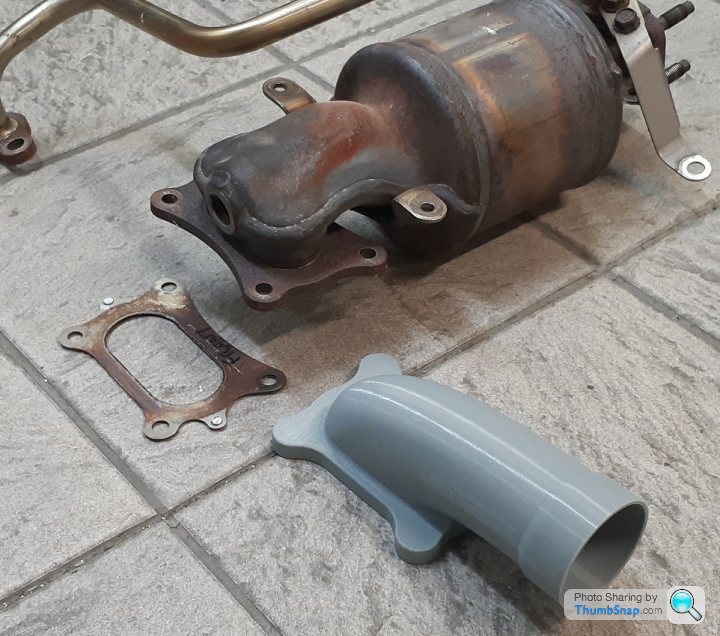
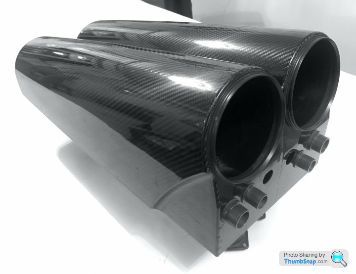
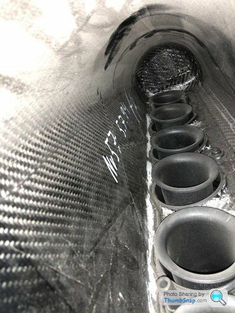
The standard J35 exhaust is a fairly odd piece of work, hard to believe that the right angle at the headifold can still produce 270hp, so hoping the spitfire style of exhaust "manifold" flows the same or better. Won't know how power is affected on the test engine as no intention at this early stage of measuring on a dyno, however once the chassis is proven reliable and body completed then effort can be spent on engine development.
The standard J35 exhaust is a fairly odd piece of work, hard to believe that the right angle at the headifold can still produce 270hp, so hoping the spitfire style of exhaust "manifold" flows the same or better. Won't know how power is affected on the test engine as no intention at this early stage of measuring on a dyno, however once the chassis is proven reliable and body completed then effort can be spent on engine development.
F1natic said:
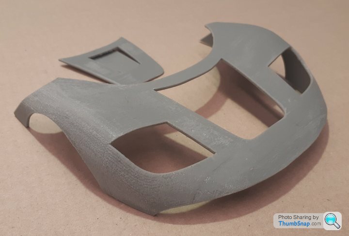
3D print of nose at 1/10 scale has turned out good, surfacing is as desired. Wall thickness has to be exagerated otherwise the parts risk misprinting.
1/10 scale door skin.
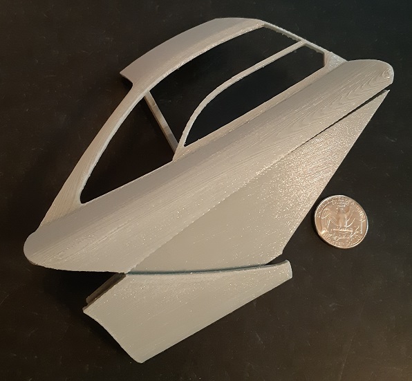
Going to focus on chassis detailing for the next couple of weeks - got some MDF today for the cabin mock up but my carpentry skills will get stretched.
If I could do those wee models of be over the moon. Let alone the actual bloody car!1/10 scale door skin.
Going to focus on chassis detailing for the next couple of weeks - got some MDF today for the cabin mock up but my carpentry skills will get stretched.
Edited by F1natic on Sunday 25th August 09:56
F1natic said:
Not my area of expertise (yet), any way of doing a flow measurement DIY with meaningful results? I don't know anyone with a spare flowbench unfortunately..
One thing you can try , if you have the space and facilities , is , fill a big tank full of water , weld/make/connect a flange to the side of the tank , and then bolt on your two different elbows , and time how long it takes to empty the tank through them ? or just how long it takes for the water level to drop by a set amount . 
J4CKO said:
a replica of the "Eleanor" car in gone is Sixty Seconds,
Specifically it is the use of the name Eleanor that is copyrighted rather than the specific modifications on the car.F1natic said:
Not my area of expertise (yet), any way of doing a flow measurement DIY with meaningful results? I don't know anyone with a spare flowbench unfortunately..
Check to see if your CAD package has an add on for fluid dynamics and flow, which could be used to do a reasonably accurate simulation. Although some add ons seem silly expensive. I'm using Fusion 360 to design my single seater and all the fancy fluid dynamics and FEA add ons are only available on the full business packages at some silly monthly subscription. Fine for business users not so much for hobbyists.ivanhoew said:
One thing you can try , if you have the space and facilities , is , fill a big tank full of water , weld/make/connect a flange to the side of the tank , and then bolt on your two different elbows , and time how long it takes to empty the tank through them ? or just how long it takes for the water level to drop by a set amount .
Remember that water is incompressible where as air is, so as a very rough guide it may be fine but beyond that it won't be so accurate a measurement. Psycho Warren said:
Remember that water is incompressible where as air is, so as a very rough guide it may be fine but beyond that it won't be so accurate a measurement.
Would that matter for a like for like comparison rather than actual figures? I.e. if one flows water better than the other it will likely flow air better too?I was taught early on that all models are wrong, but some are useful. After the body is built I intend to improve the flow on the stock heads and cams, however I have an intimidating list of tasks ahead, that even though I would like to get everything perfect on the first pass, it is more time/money efficient in such a high risk design to get to the kill milestones as soon as possible. Design is iterative, and my prime focus currently is to get the design application completed (90% there, only 90% to go), fire up the test engine on the Speeduino ECU then build the driveable stage one rolling chassis.
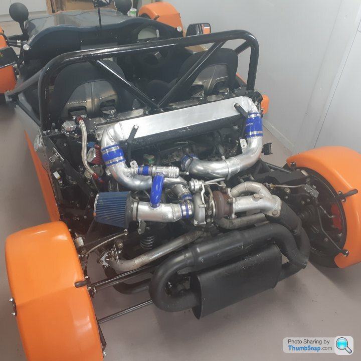
In this instance the functional requirement for the manifold is to exhaust gas out the front cylinder heads with the minimum of forward sweep, as clearance is about 120mm from the back of the passenger seat at the closest point. Even if I kill a few horsepower initially by having sub-optimal manifolds there will be enough torque to prove out the transmission reliability. A benefit of having the engines mounted on a subframe is the ease of swapping out major components such as the exhaust system. The engine bay is very tight and awkward to reach from the rear engine cover so most minor servicing is being carried out from underneath. The challenging jobs will be changing the spark plugs and setting the valve clearances - very likely impossible with the engines installed. Every design has compromises and even though these are bad ones, the service intervals on platinum plugs and valves are so wide that pulling the sub-frame every 5 years won't be that much of a burden.
I am glad nobody asked how to check the oil level in the two engines, because I hadn't a worked out a practical solution. Engine bay access to the standard dipsticks positions is very awkward. As luck would have it I met a fellow car builder at the Caffeine and Classics at Smales Farm today. His midengined 4wd open top sports car uses a mix of Subaru WRX and honda parts (so engrossed in the detail I didn't even take a photo dammit) and has a self built dry sump system using ford small block oil pump gerotors. So I have just dropped the idea of using the stock wet sumps and will dry sump the prototype, which is a huge relief as that was a vulnerability I wanted to eliminate. Each engine will therefore have its own oil cooler and dry sump tank in the adjacent flank. The oil level will be easily checked by opening the flank panels for access, as there was no room for luggage space anyway. The gas filler cap will also be accessed by opening the left flank hatch. The relay panel, ECU's and battery are positioned on the floor behind the passengers.
Edited by F1natic on Sunday 31st January 01:58
Absolutely agree F1 , it was just in case you were confused by the results ,and were assuming that grey elbow must be better .
I built a turbocharged 400/4 in 1980 and could not get more than 13 psi boost out of , just as well since i had to use it for 10k miles as my long distance courier bike ,and it never blew up prob due to my boost ceiling .
A few years later i replaced the turbo downpipe with a bigger bore smoother angled elbow on the turbine ,,instant 15 psi , and boost came in about 3oo rpm earlier . bonus ! .....goodbye clutch !
Caddyshack said:
Would that matter for a like for like comparison rather than actual figures? I.e. if one flows water better than the other it will likely flow air better too?
Sure in all likely hood yes. but its a rough guide and should be treated as such. F1natic said:
Engine bay access to the standard dipsticks positions is very awkward.
For simple day to day use, rob a oil level sensor from an OEM car. Quite a few cars over the years have something suitable. Some of the older stuff may be simpler to wire in than the more modern stuff that likely feeds into the ECU direct and then into CANBUS or into a CANBUS network before it even gets to the ECU. Thanks PW, that is a good option to consider for oil level monitoring.
Have detailed the fuel system components in the 4B application notes, the fuel pump is sourced from the main tank of a post 2008 C6 corvette - a great explanation of operation of the corvette system is here;
https://www.xlr-net.com/knowledgebase/article/2004...
Only have one tank so the pressure feed to the non-existent siphon jet pump will be blocked off. The honda engines also use a non-return style fuel injection layout running at 58 psi, so the GM pump will match perfectly.
Need to ensure that there is a small recess in the bottom of the tank to position the foot of the pump assembly, which has a venturi pump at the lowest point to scavenge the dregs of fuel in a low tank and thus always keep the pump cool by having the pump reservoir full even if the tank level around it is low.
Edited by F1natic on Sunday 7th February 09:57
Psycho Warren said:
Mercedes are well known for going after people trying to make gullwing replicas and have taken extra measures to protect the design.
This is just one example:
https://www.topgear.com/car-news/merc-destroys-300...
Points I failed to note on first reading of this article are that only the fibreglass body was crushed and that shell weighed (only) 148kg. This is just one example:
https://www.topgear.com/car-news/merc-destroys-300...
Edited by F1natic on Wednesday 10th February 04:13
The NZ govt is providing some funding to help run the LVVTA, which has meant that the NZ car construction manual is now free for download - my favourite price.
4B detail drawings and specifications running at 60 A4 pages currently - when done will be very close to 100. Good thing with CAD is it is easy to take snapshots of the required detail with very little further work.
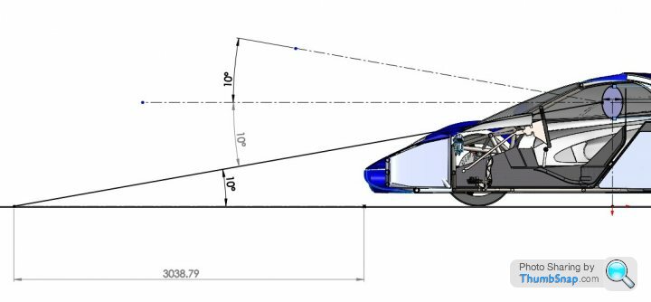
Have never driven a car where you can see the road 3m in front of the nose - that is going to take some mental adjustment.
4B detail drawings and specifications running at 60 A4 pages currently - when done will be very close to 100. Good thing with CAD is it is easy to take snapshots of the required detail with very little further work.
Have never driven a car where you can see the road 3m in front of the nose - that is going to take some mental adjustment.
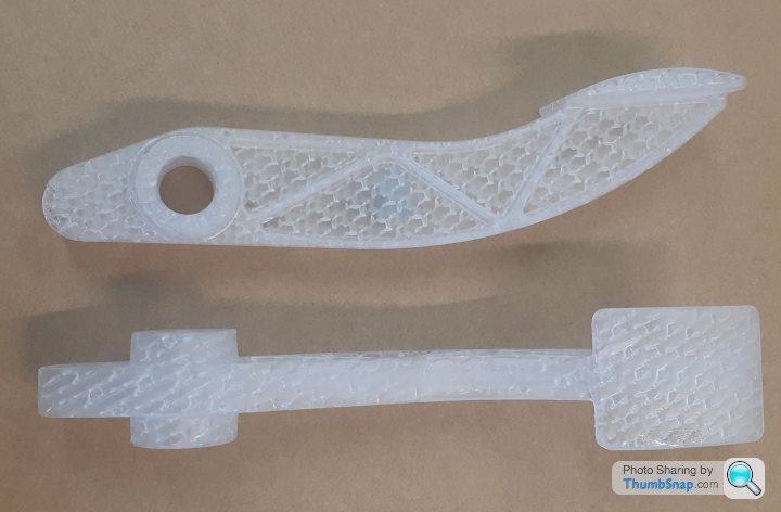
SLA patterns for the brake pedal arrived this morning. Surface finish on these patterns are as good as production waxes from polished aluminium tooling, and much better than FDM from desktop 3D printers. A good shotblast after casting and you would be hard pressed to know the difference.
Below is the "Freewheel" sports car with the rear cover removed showing the WRX motor dry sumped using ford M68 oil pump internals and inhouse machined scavenge housings (literally inhouse, the car and workshop are in the owners downstairs converted bedrooms!)
4wd, 780Kg, 240hp and road registered, brilliant.
The front viewing angle is more a requirement for the people building front engined hot rods with large blowers that can take up a lot of the frontal view. Depending on the width of the protrusion the sight line must fall between 8m to 15m in front of the vehicle. Not an issue for middy builders, the 3m is just the number that falls out with this configuration and is well within range.
Edited by F1natic on Tuesday 16th February 18:09
Gassing Station | Readers' Cars | Top of Page | What's New | My Stuff