500+bhp Mk3 Fiesta Project
Discussion


Engine Mount - Inclination Adjustment
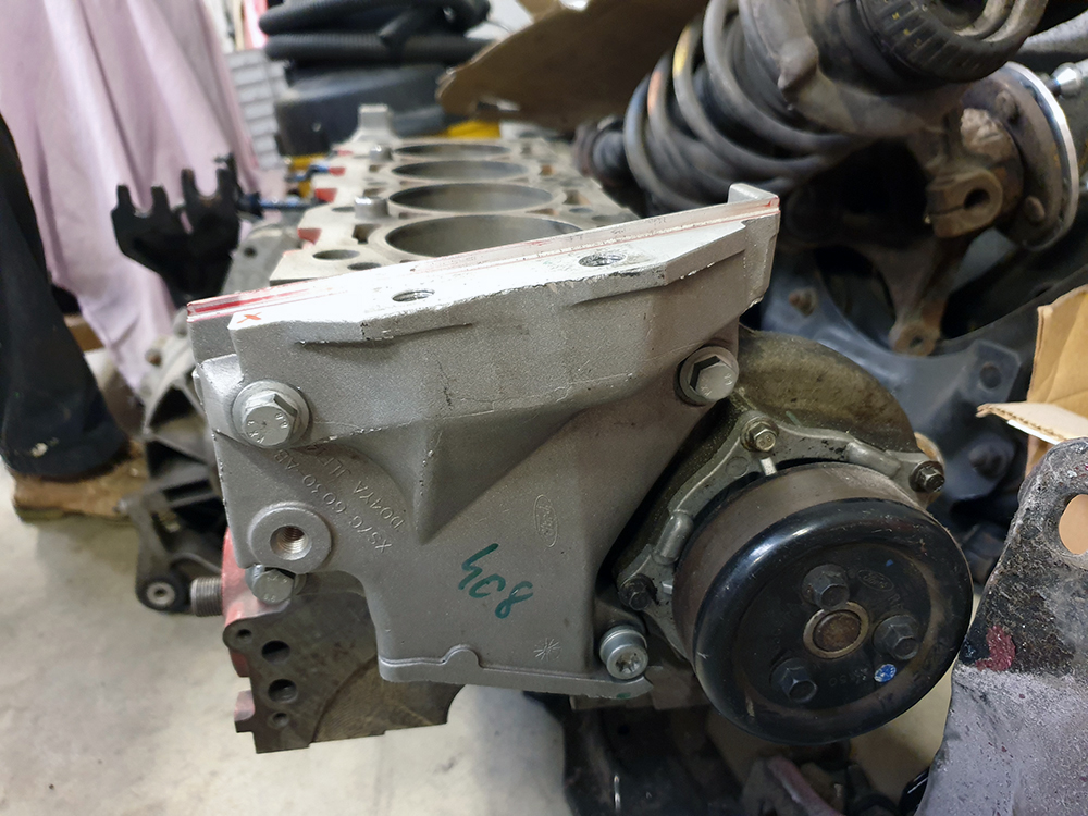
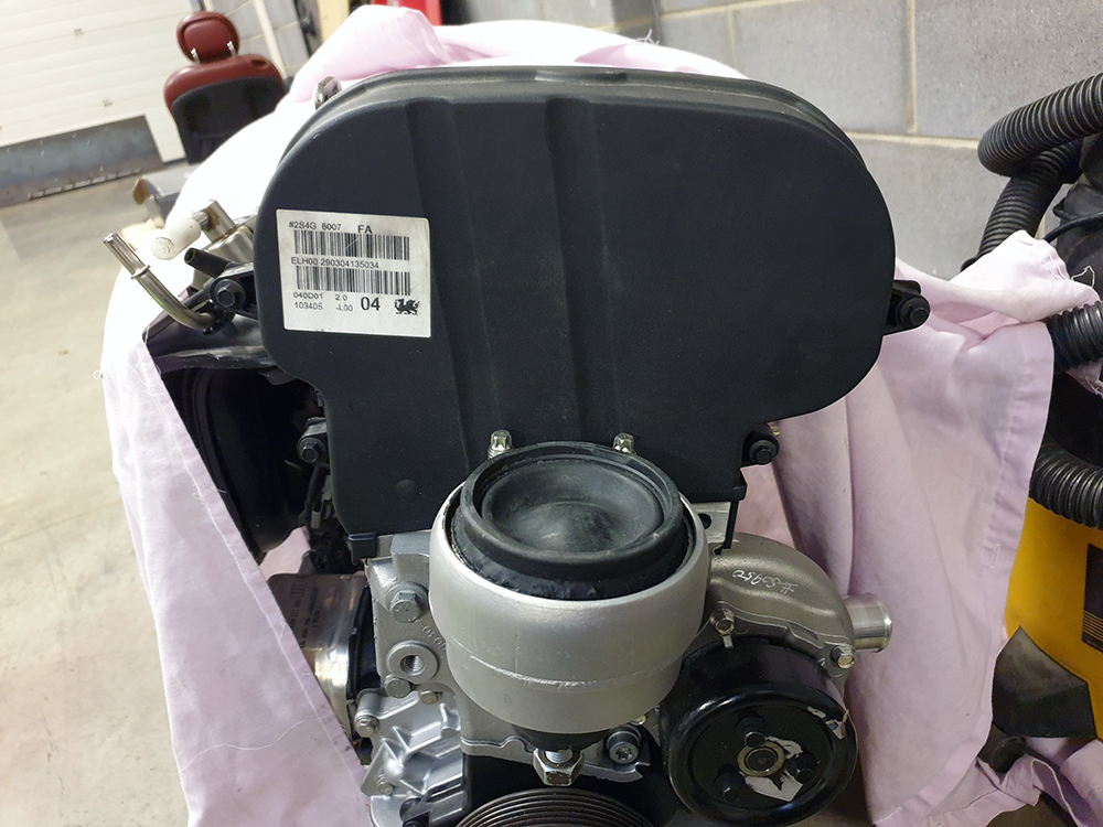
I mentioned in a previous post that the 'Black Top' Zetec engines are mounted with a forward inclination, and with that in mind I had redesigned the front crossmember to allow for a larger radiator with intercooler, A/C condenser, and sufficient room for a four branch manifold to mount the turbo over the gearbox. I've since decided to use a manifold with shorter primaries for better turbo response - which means that I now need more space around the front of the engine.
Here is a shot of the engine mount bracket which clearly illustrates the inclination. I decided to re-engineer this part to mount to provide purpendicular mounting of the engine.
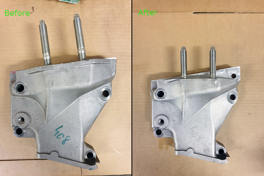
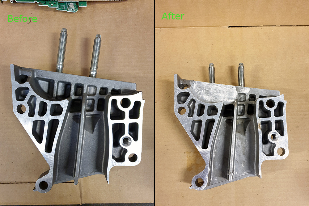
Finished result below. The process involved welding up the original tapped holes, and some pockets on the rear which would have been exposed as holes after the mounting surface was milled at 90 degrees.
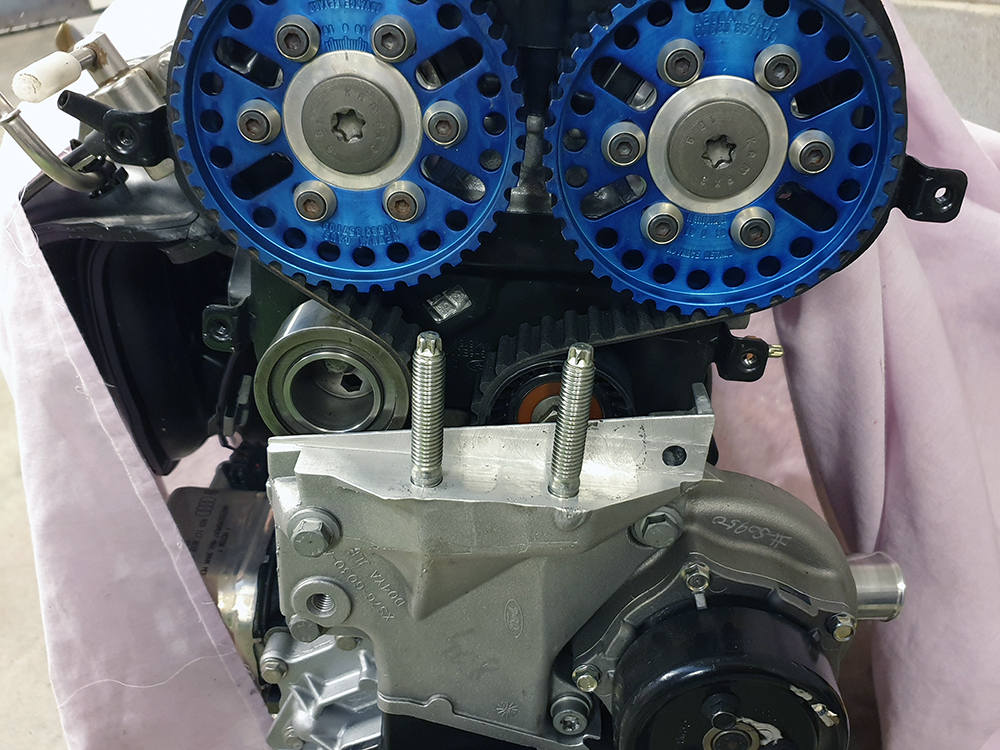
Mount bracket installed on my engine, and another photo of the mount installed.
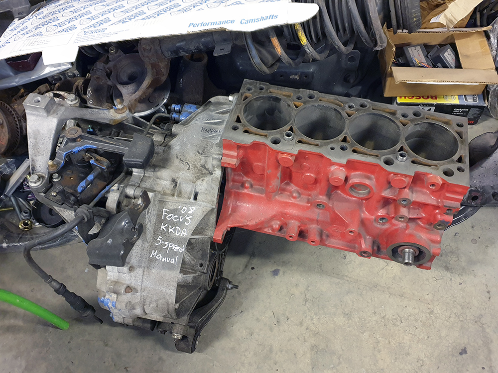
The Focus RS MTX75 gearbox I have is suited to the forward inclination, and after studying it I decided that are too many bellhousing reinforcement ribs to make modifying it a realistic option, plus there is a real risk of heat distorting the differential bearing mountings. I researched alternative MTX75s and was surprised to find at least 15 different variations - I found a version from the Mk3 Focus that will suit my needs; I'll rebuild it with the Focus RS internals.
Mock up engine and gearbox below. I will modify the engine sump and lower gearbox mount to suit the new engine position.
I mentioned in a previous post that the 'Black Top' Zetec engines are mounted with a forward inclination, and with that in mind I had redesigned the front crossmember to allow for a larger radiator with intercooler, A/C condenser, and sufficient room for a four branch manifold to mount the turbo over the gearbox. I've since decided to use a manifold with shorter primaries for better turbo response - which means that I now need more space around the front of the engine.
Here is a shot of the engine mount bracket which clearly illustrates the inclination. I decided to re-engineer this part to mount to provide purpendicular mounting of the engine.
Finished result below. The process involved welding up the original tapped holes, and some pockets on the rear which would have been exposed as holes after the mounting surface was milled at 90 degrees.
Mount bracket installed on my engine, and another photo of the mount installed.
The Focus RS MTX75 gearbox I have is suited to the forward inclination, and after studying it I decided that are too many bellhousing reinforcement ribs to make modifying it a realistic option, plus there is a real risk of heat distorting the differential bearing mountings. I researched alternative MTX75s and was surprised to find at least 15 different variations - I found a version from the Mk3 Focus that will suit my needs; I'll rebuild it with the Focus RS internals.
Mock up engine and gearbox below. I will modify the engine sump and lower gearbox mount to suit the new engine position.


Thanks all.
Rear-View Mirror Upgrade #2
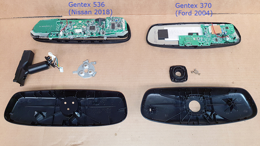
I had retrofitted a Mk3 Mondeo auto-dimming rear view mirror together with its auto lights and wiper system. The Mondeo mirror is made by Gentex, and I noticed that there were some later models equipped with an electronic compass, and garage door opener. I wanted one. Gentex are the OEM for many manufacturers, and despite looking similar, there are actually many different variations of the auto-dim mirror; I found a suitable candidate in a 2018 Nissan - it has green compass letters to match the Ford illumination. Most Gentex mirrors look similar, and I wondered if I could place the upgraded internals within the Mondeo mirror, but when the mirror arrived it turned out that everything was different.
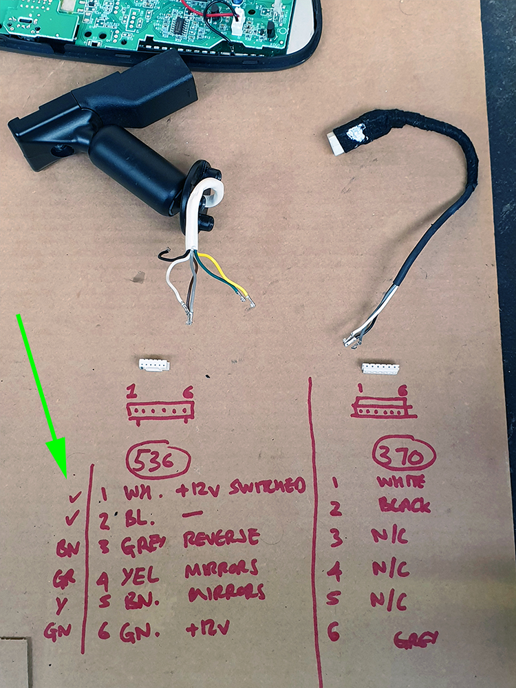
The Mondeo mirror is a Gentex 370. Its mounting system uses a screw-in boss to which the swivel ball is mounted.
The Nissan mirror is a Gentex 536. It's mounting system features a self-contained swivel assembly which bolts to a metal mounting plate within the mirror case.
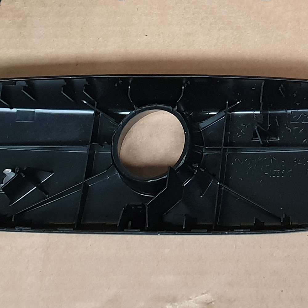
Swapping to the Nissan mounting system would involve finding a new solution to mount the Ford rain & light sensor, and dictate removal of the mounting button from the windscreen to bond in the Nissan version. It would be too much work and too disruptive - I also preferred the Ford trim piece around the light sensor.
After a little bit of thought I came up with a solution that involved modifying the Nissan mirror case to accept the Ford swivel ball mount. First, I had the rear case of the Nissan mirror milled to accept the round part of the Ford boss as an interference fit.
Next, I drilled and countersunk the Nissan case so that I could use machine screws to secure the Ford boss. For added durability, and to prevent the countersunk heads migrating through the plastic case over time, I used JB Weld to reinforce the inside of the case where the fastenings pass through.
The internal wiring turned out to be a case of matching pin position with wire colour, as both mirror types use the same wire colour scheme internally; the vehicle manufacturer wiring scheme starts at the external mirror connection. The terminals and pins were slightly different between mirrors, however they turned out to be compatible.
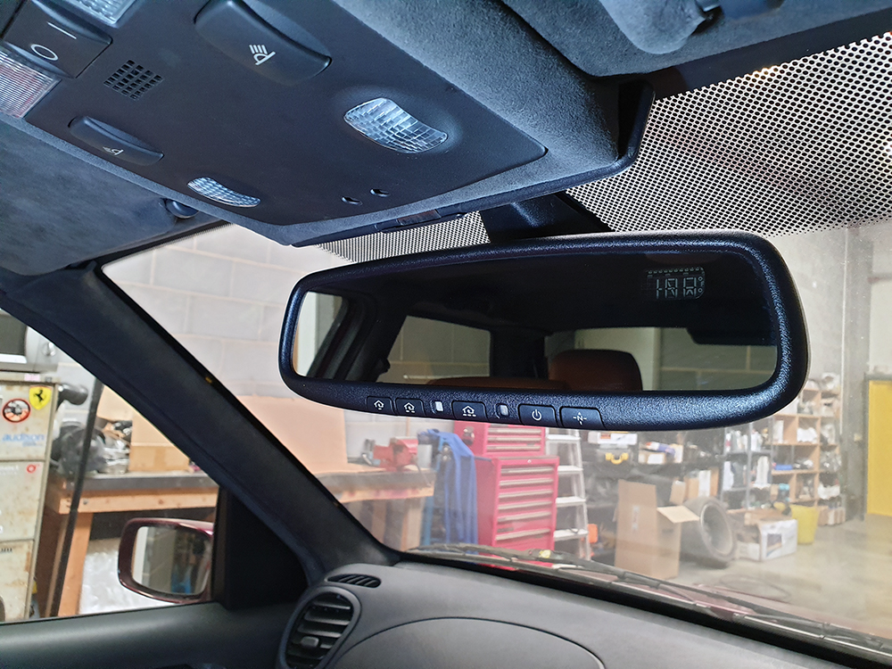
Conversion complete. I'm happy with it.
Rear-View Mirror Upgrade #2
I had retrofitted a Mk3 Mondeo auto-dimming rear view mirror together with its auto lights and wiper system. The Mondeo mirror is made by Gentex, and I noticed that there were some later models equipped with an electronic compass, and garage door opener. I wanted one. Gentex are the OEM for many manufacturers, and despite looking similar, there are actually many different variations of the auto-dim mirror; I found a suitable candidate in a 2018 Nissan - it has green compass letters to match the Ford illumination. Most Gentex mirrors look similar, and I wondered if I could place the upgraded internals within the Mondeo mirror, but when the mirror arrived it turned out that everything was different.
The Mondeo mirror is a Gentex 370. Its mounting system uses a screw-in boss to which the swivel ball is mounted.
The Nissan mirror is a Gentex 536. It's mounting system features a self-contained swivel assembly which bolts to a metal mounting plate within the mirror case.
Swapping to the Nissan mounting system would involve finding a new solution to mount the Ford rain & light sensor, and dictate removal of the mounting button from the windscreen to bond in the Nissan version. It would be too much work and too disruptive - I also preferred the Ford trim piece around the light sensor.
After a little bit of thought I came up with a solution that involved modifying the Nissan mirror case to accept the Ford swivel ball mount. First, I had the rear case of the Nissan mirror milled to accept the round part of the Ford boss as an interference fit.
Next, I drilled and countersunk the Nissan case so that I could use machine screws to secure the Ford boss. For added durability, and to prevent the countersunk heads migrating through the plastic case over time, I used JB Weld to reinforce the inside of the case where the fastenings pass through.
The internal wiring turned out to be a case of matching pin position with wire colour, as both mirror types use the same wire colour scheme internally; the vehicle manufacturer wiring scheme starts at the external mirror connection. The terminals and pins were slightly different between mirrors, however they turned out to be compatible.
Conversion complete. I'm happy with it.
Fuel Filler Neck Part 1: The Problem
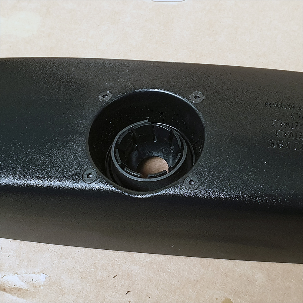
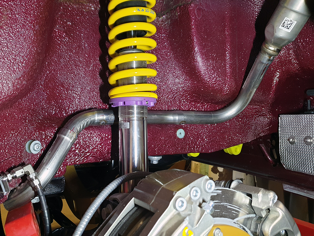
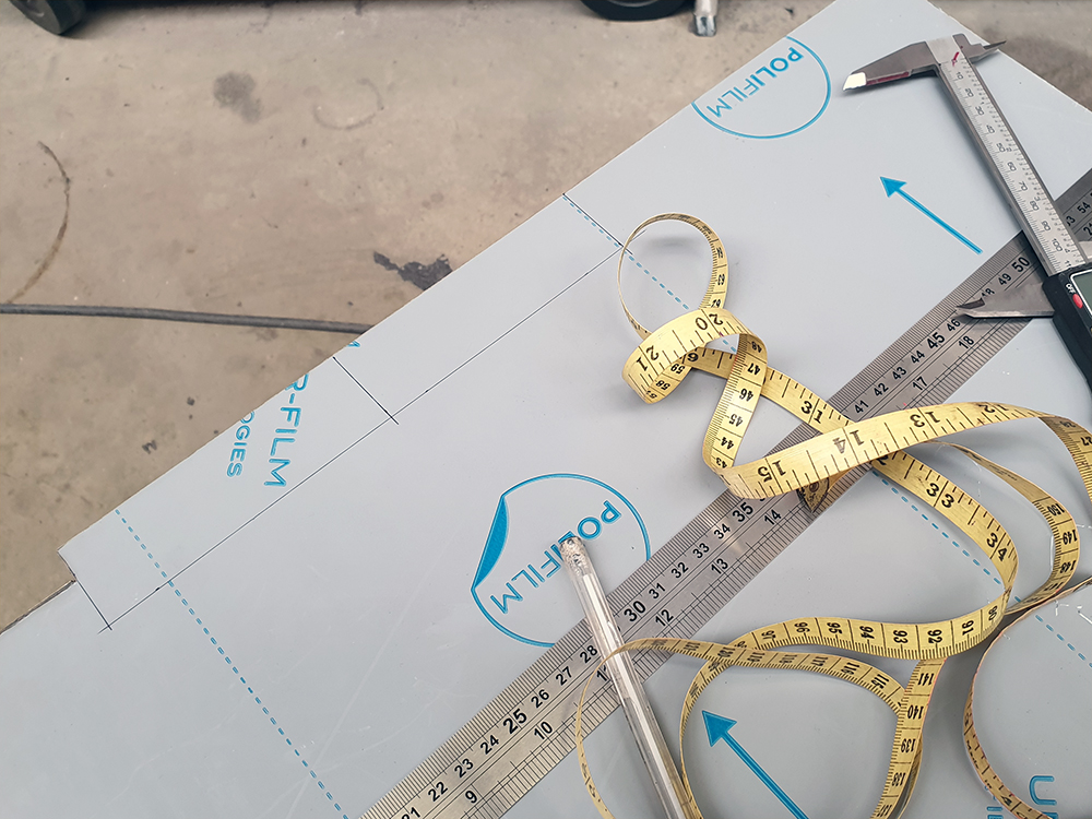
The original Fiesta filler neck wasn't going to work in standard form. It follows a route from the N/S/R wheel arch diagonally across the boot floor to the fuel tank mounted under the rear seats, but the problem is that there is now a Focus rear subframe & independent suspension components occupying some of that space under the boot floor.
The following photos illustrate the problem - I had to cut the end off of the original neck (just a scrap test part) to even mount it inside the wheelarch.
Due to various constraints, the new filler pipework must pass inside the wheelarch. I cut open the test filler neck to determine if it would be feasible to maintain the original Fiesta opening and fuel cap, to which I could add modified pipework to connect the tank, however due to the construction of the original neck I would have nowhere to attach a new section of pipework.
Note the grounding strap employed to prevent issues arising from electrostatic discharge whilst filling.
Given that no parts of the Fiesta filler neck could be used, a clean-sheet solution was required.


Fuel Filler Neck Part 2: Prototype
As often as not, these projects involve more time spent researching than they do wielding tools, and the filler neck was no exception. My intent was to utilise an existing part rather than fabricate an assembly from scratch, or a generic filler cap assembly. I also try to stick to one of my principles to use Ford parts where possible in order to simplify future maintenance requirements - though obviously that one often does not work out.
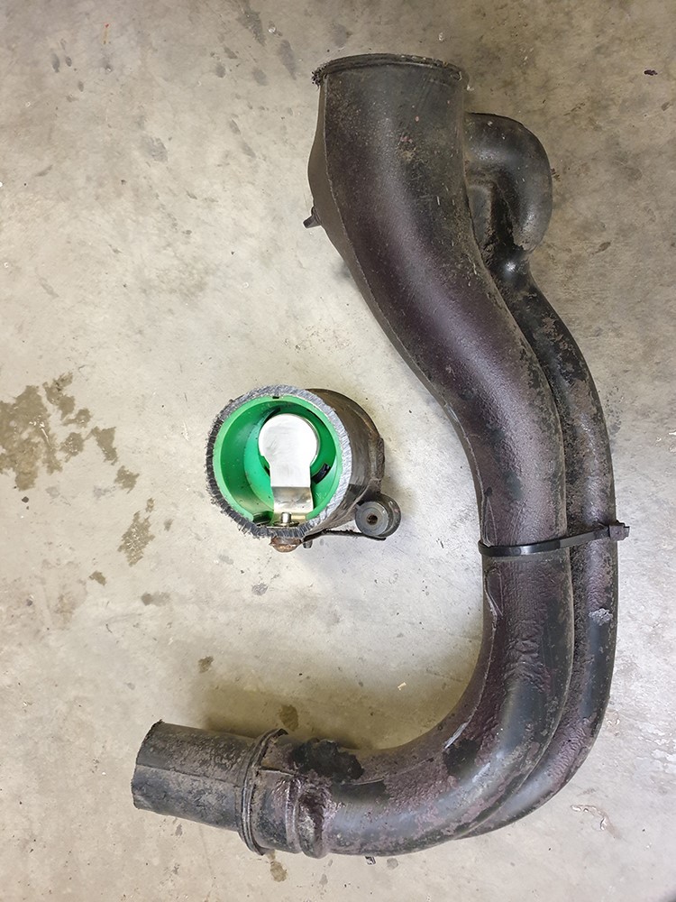
Several hours of visual research led me to the Mk7/2008 Fiesta filler neck. The material, form, and overall dimensions looked suitable. This type of research takes me so far but the next, and most enjoyable step is to order a used part to get an impression of the physical part. I liked the Mk7 generation as Ford appeared to switch to stainless - the previous generation (I know them as the Mk6) seem to rust terribly and its form appeared useless for my application. The Mk7 filler neck had sufficient tube length & bends to be useful as raw material to fashion something bespoke for my car.
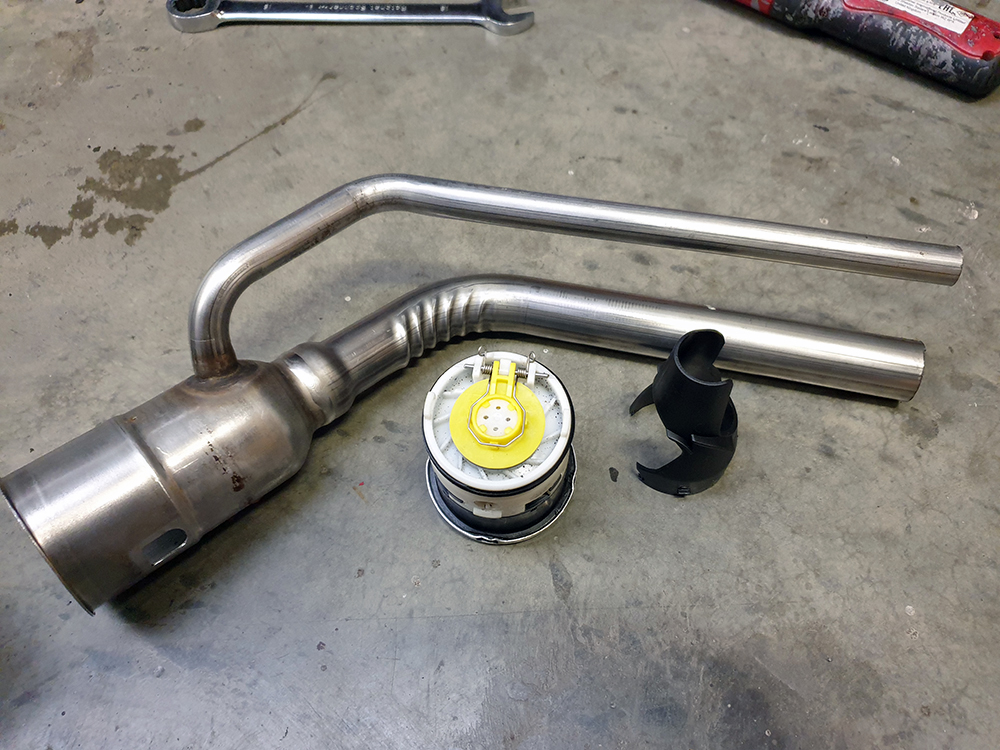
The image below shows the Mk3 filler neck (top) and the Mk7 filler neck (bottom).
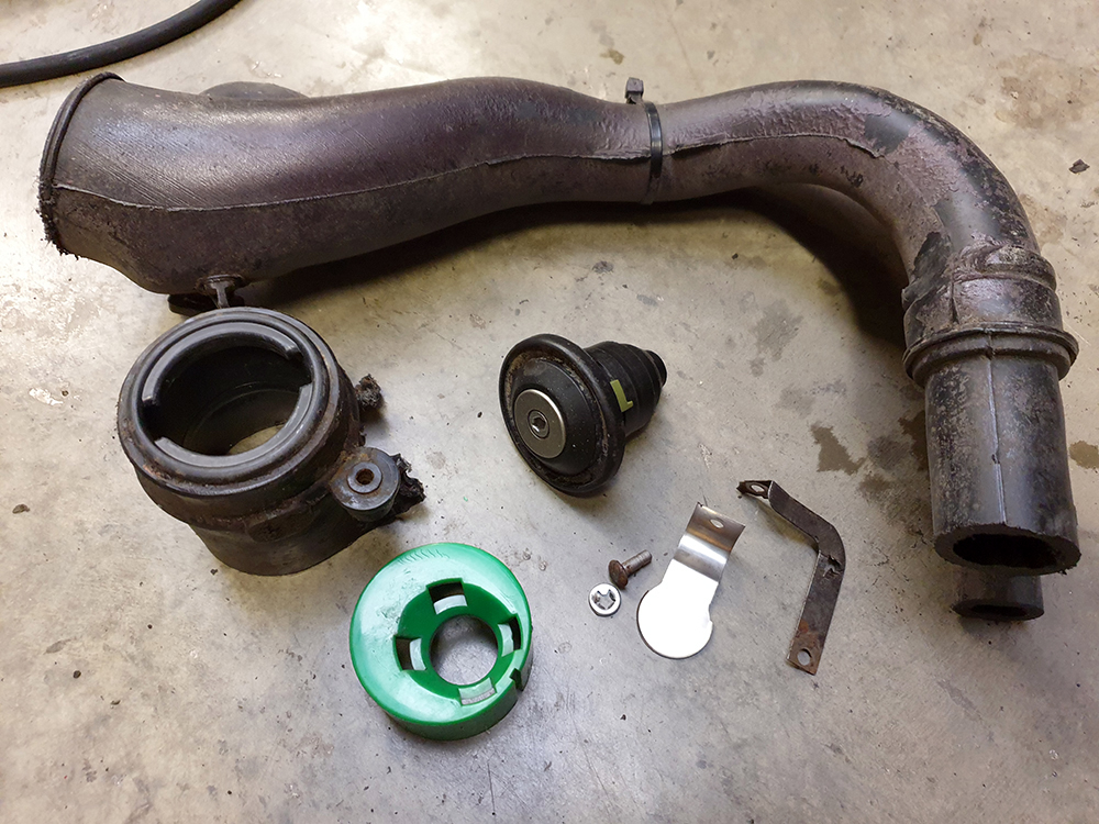
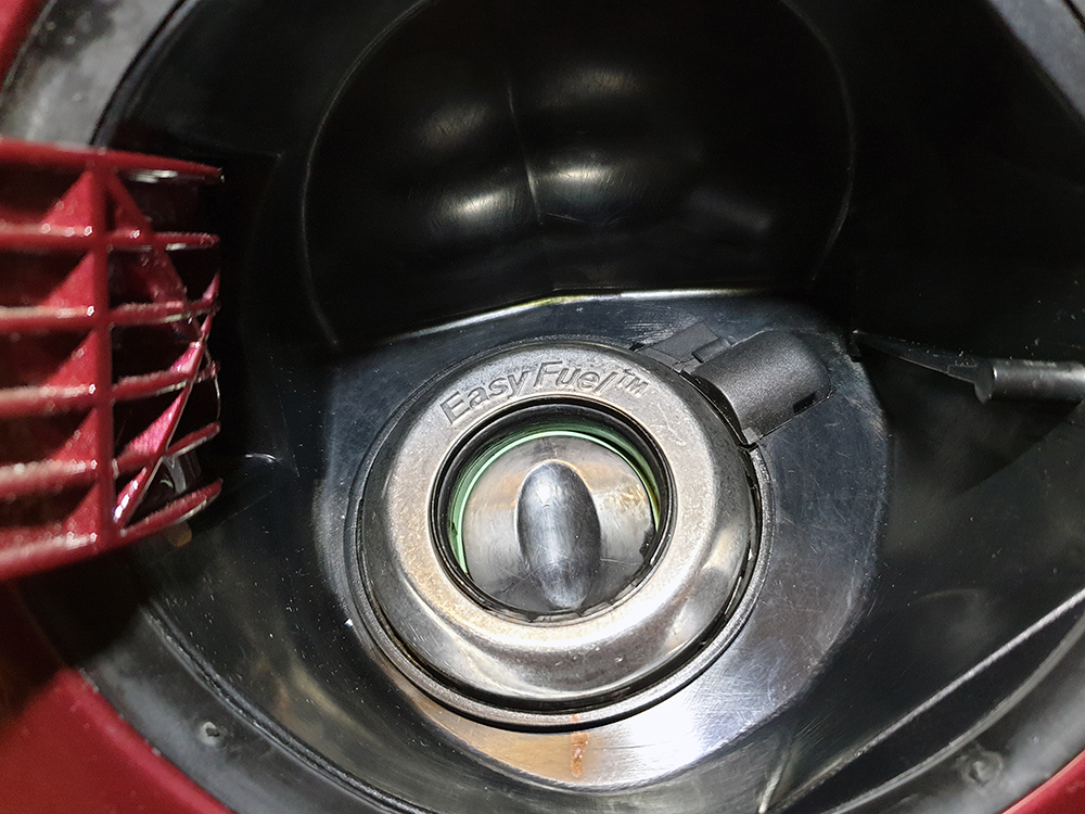
Dissection of the Mk7 part revealed an early incarnation of Ford's capless 'Easy Fuel' system, which is designed to increase convenience by preventing filling with the wrong fuel, and at the same time replacing the security provided by a locking cap with an internal mechanism. I measured the filler diameter with my verniers and found that the circumference was only 2-3mm less than the original Mk3 part - close enough.
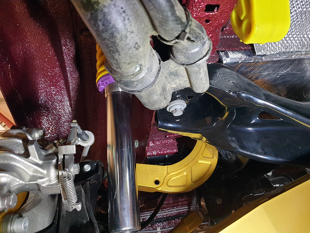
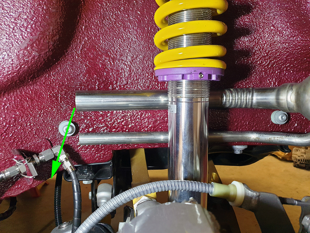
With a suitable candidate part found I could evaluate my idea in physical form. I had a number of constraints to work with: the boot floor was out - the pipes must pass within the wheelarch, I was using larger than the OEM KW coilovers, I had converted to Focus IRS which placed a suspension arm close to the leading inside edge of the wheelarch, and I had added fastenings for Mk4 Fiesta wheelarch liners. The only space left was behind the brake line brackets.
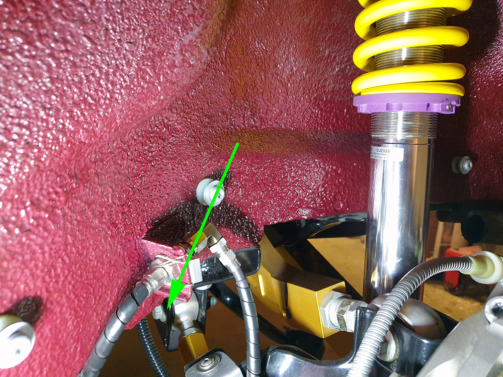
At this stage I was happy to proceed with a PoC. The suspension was at full droop with my set ride height, and I had confirmed clearance at full compression. It was tight, but feasible.
As often as not, these projects involve more time spent researching than they do wielding tools, and the filler neck was no exception. My intent was to utilise an existing part rather than fabricate an assembly from scratch, or a generic filler cap assembly. I also try to stick to one of my principles to use Ford parts where possible in order to simplify future maintenance requirements - though obviously that one often does not work out.
Several hours of visual research led me to the Mk7/2008 Fiesta filler neck. The material, form, and overall dimensions looked suitable. This type of research takes me so far but the next, and most enjoyable step is to order a used part to get an impression of the physical part. I liked the Mk7 generation as Ford appeared to switch to stainless - the previous generation (I know them as the Mk6) seem to rust terribly and its form appeared useless for my application. The Mk7 filler neck had sufficient tube length & bends to be useful as raw material to fashion something bespoke for my car.
The image below shows the Mk3 filler neck (top) and the Mk7 filler neck (bottom).
Dissection of the Mk7 part revealed an early incarnation of Ford's capless 'Easy Fuel' system, which is designed to increase convenience by preventing filling with the wrong fuel, and at the same time replacing the security provided by a locking cap with an internal mechanism. I measured the filler diameter with my verniers and found that the circumference was only 2-3mm less than the original Mk3 part - close enough.
With a suitable candidate part found I could evaluate my idea in physical form. I had a number of constraints to work with: the boot floor was out - the pipes must pass within the wheelarch, I was using larger than the OEM KW coilovers, I had converted to Focus IRS which placed a suspension arm close to the leading inside edge of the wheelarch, and I had added fastenings for Mk4 Fiesta wheelarch liners. The only space left was behind the brake line brackets.
At this stage I was happy to proceed with a PoC. The suspension was at full droop with my set ride height, and I had confirmed clearance at full compression. It was tight, but feasible.
Fuel Filler Neck Part 3: Fabrication
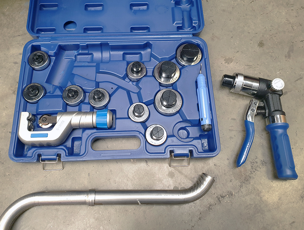
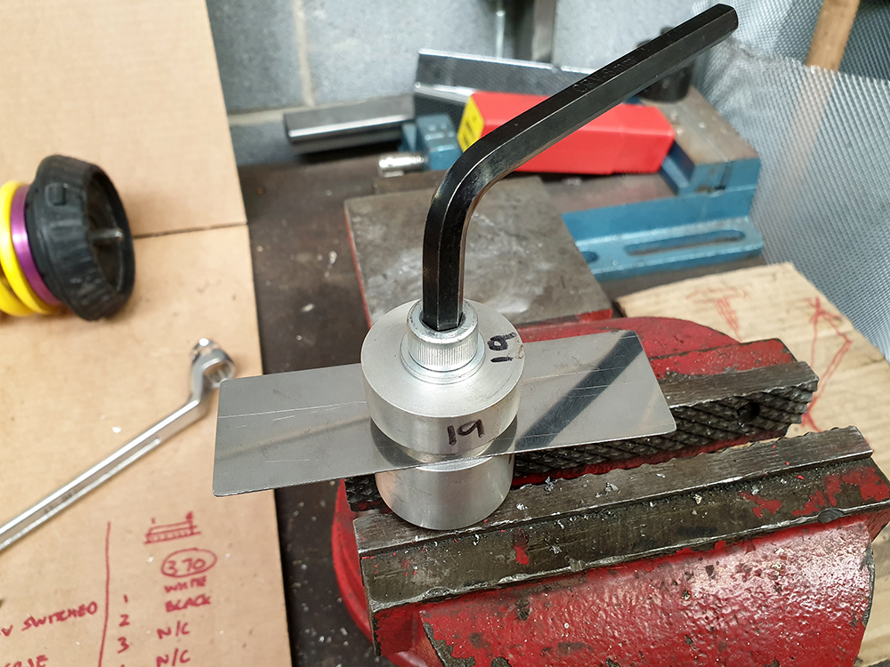
Without a doubt my new favourite tool is this hydraulic pipe expander which is used to create a sleeve joint on metal pipe. It comes with an adjustable pipe cutter, and a de-burring tool, all of which are ideal for this job. The best part was it was free: I received some Amazon vouchers at work as part of an award, so I went straight to the the tools section to order this. My plan was to chop up the Mk7 filler neck and use the new tool to create joints, as the tool would provide flexibility to create slightly more clearance than necessary, allowing the joints to meet at varying angles.
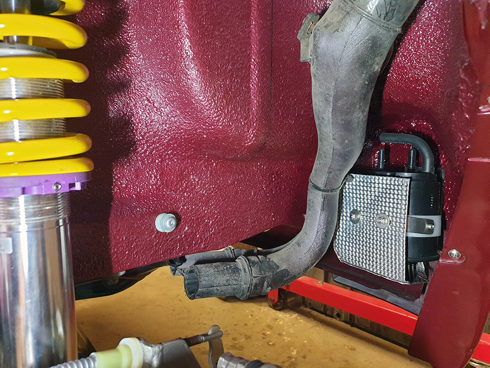
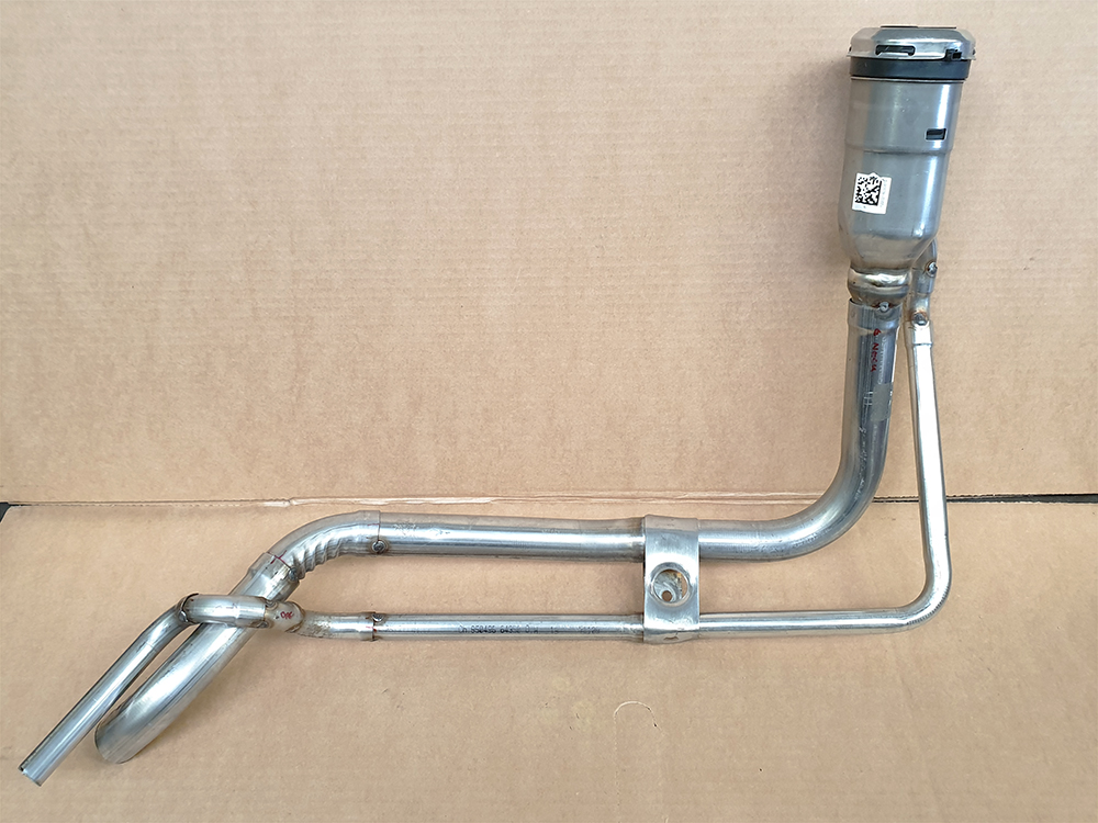
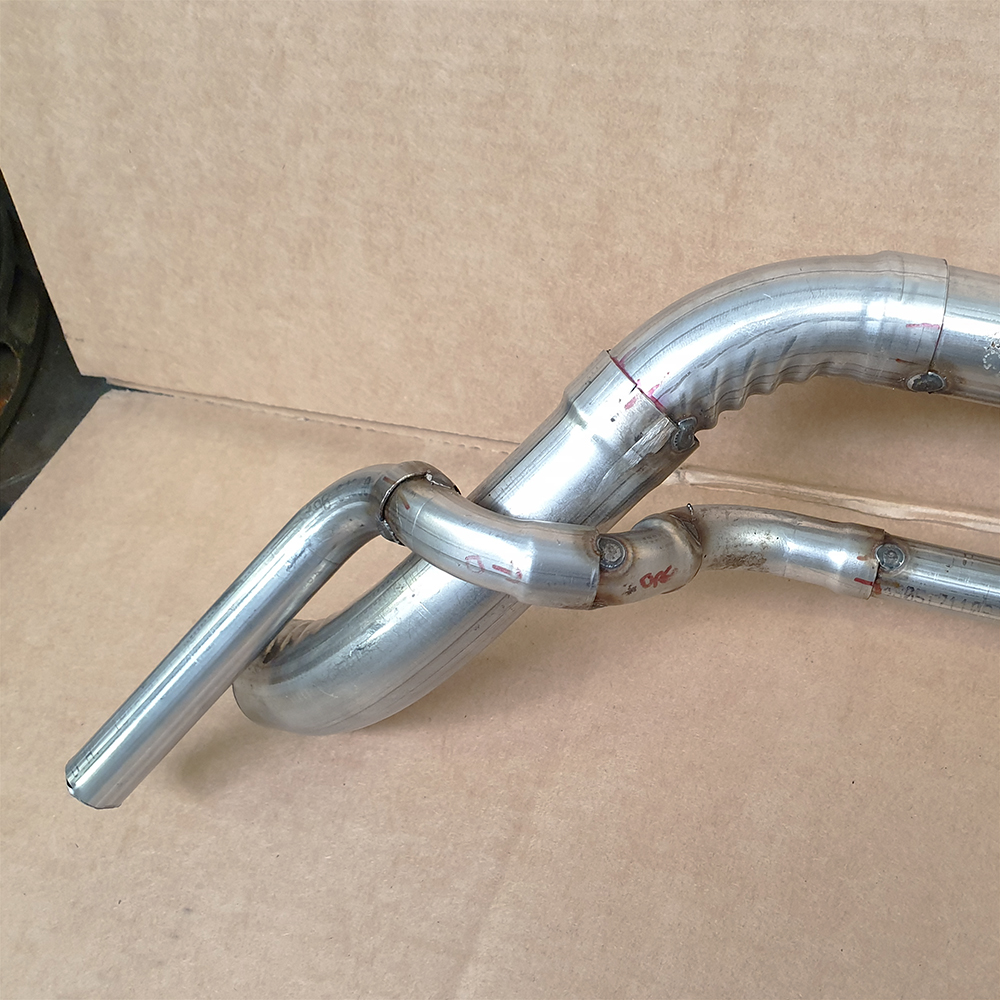
I started with the main filler pipe. I made an initial prototype, and decided that I could improve, so here is the second iteration - propped up by a red Powerflex exhaust mount until I fabricate a securing bracket. There are various angles in play inside the wheelhousing and reaching this point was more time consuming than it may appear.
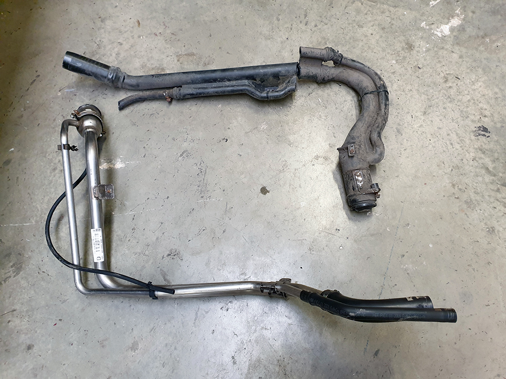
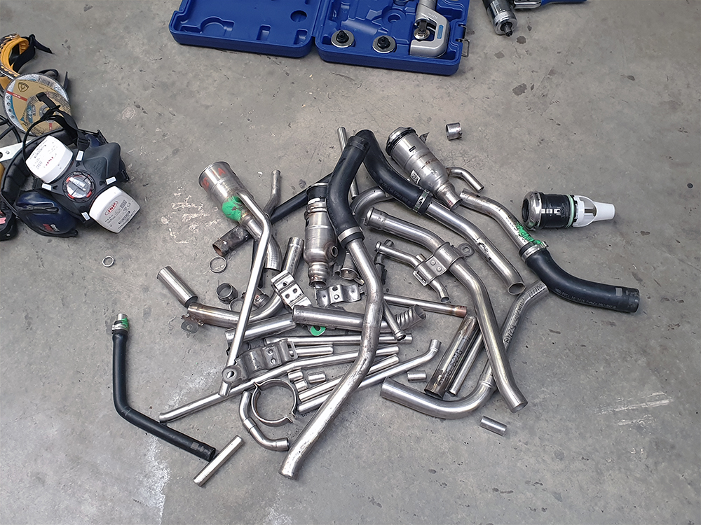
Here's the pile of bits I was left with. In the end I had used four Mk7 filler necks. If the need arises to make another then I could reduce that figure to two
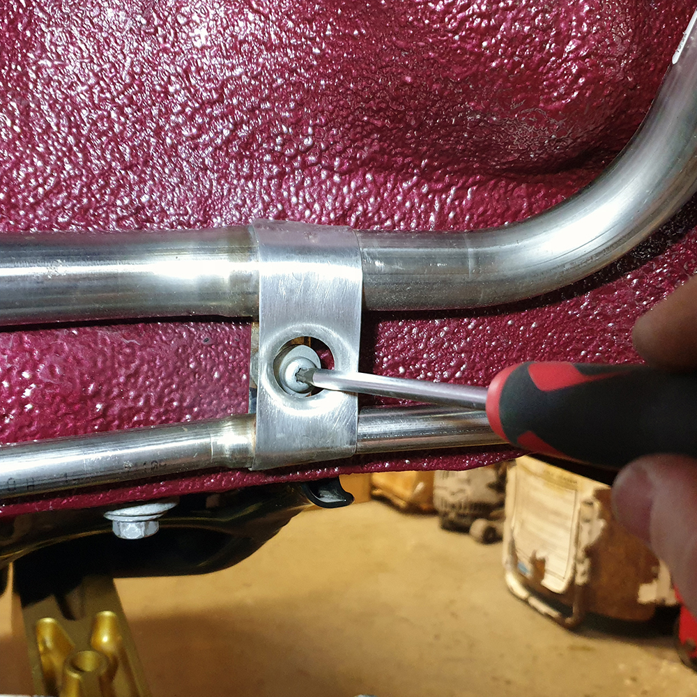
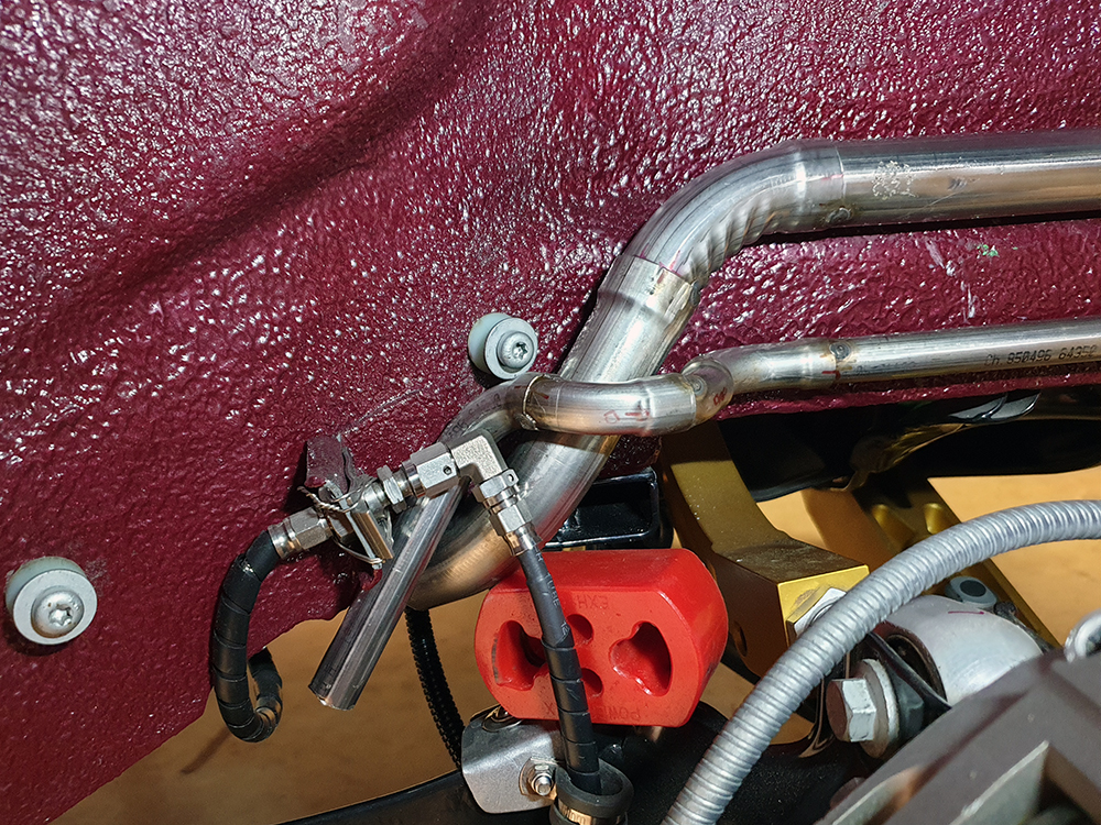
Here's the assembly with breather pipe and the first bracket. At this stage the joints are just tack welded in place, but when final welding takes place I will add a second bracket/strap, and make sure that the pipes are parallel.
The following three photos show some of the fabrication process of the securing strap. The swaged hole adds strength, reduces weight, and provides clearance to the mounting fastening.
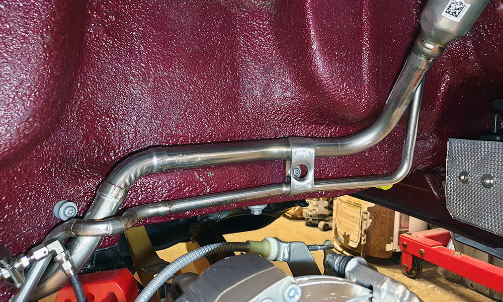
Here is the completed assembly fitted to the car. I'm pleased with the outcome.
It isn't quite finished: I'm waiting for some Argon to arrive so that I can TIG the joints together, I have a second swaged strap to add to the straight section in the wheelarch, another fastening at the front of the wheelarch, and finally the connection to the tank itself - which is being fabricated by a friend.
Without a doubt my new favourite tool is this hydraulic pipe expander which is used to create a sleeve joint on metal pipe. It comes with an adjustable pipe cutter, and a de-burring tool, all of which are ideal for this job. The best part was it was free: I received some Amazon vouchers at work as part of an award, so I went straight to the the tools section to order this. My plan was to chop up the Mk7 filler neck and use the new tool to create joints, as the tool would provide flexibility to create slightly more clearance than necessary, allowing the joints to meet at varying angles.
I started with the main filler pipe. I made an initial prototype, and decided that I could improve, so here is the second iteration - propped up by a red Powerflex exhaust mount until I fabricate a securing bracket. There are various angles in play inside the wheelhousing and reaching this point was more time consuming than it may appear.
Here's the pile of bits I was left with. In the end I had used four Mk7 filler necks. If the need arises to make another then I could reduce that figure to two
Here's the assembly with breather pipe and the first bracket. At this stage the joints are just tack welded in place, but when final welding takes place I will add a second bracket/strap, and make sure that the pipes are parallel.
The following three photos show some of the fabrication process of the securing strap. The swaged hole adds strength, reduces weight, and provides clearance to the mounting fastening.
Here is the completed assembly fitted to the car. I'm pleased with the outcome.
It isn't quite finished: I'm waiting for some Argon to arrive so that I can TIG the joints together, I have a second swaged strap to add to the straight section in the wheelarch, another fastening at the front of the wheelarch, and finally the connection to the tank itself - which is being fabricated by a friend.
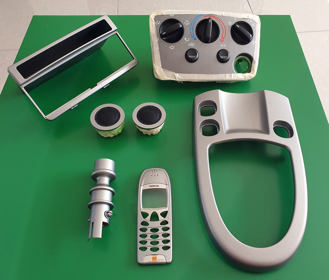
This morning I collected various interior trim pieces from the body shop. I've had them sprayed to match the Mk5 Fiesta HVAC panel & instrument cluster faascia.
Fitted. Ford phone kit in passenger foot well awaiting fitment.
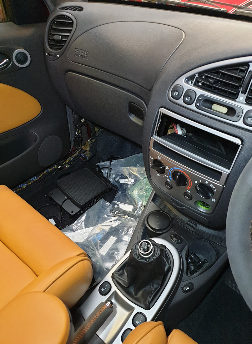
One thing I need to do is extend the gear lever to suit the Fiesta: it's a Mk1 Focus RS short-throw assembly and has a much shorter lever than the standard Focus. I will extend the shaft by 3".
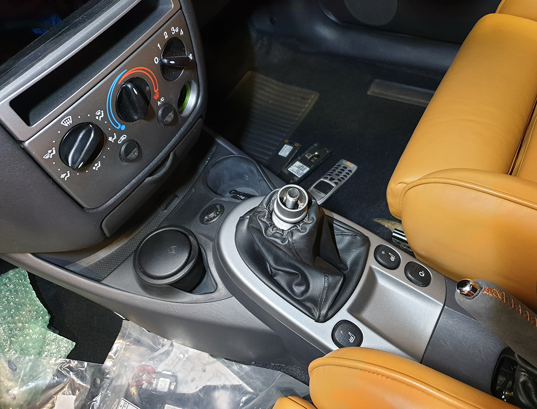
- Focus gear lever surround: originally black
- Seas Lotus tweeters: originally silver
- Mk1 Focus RS reverse lever lock: originally chrome
- Single DIN radio adapter fascia: unacceptable colour match
- Period Nokia phone for the period Ford handsfree kit: dark grey
Fitted. Ford phone kit in passenger foot well awaiting fitment.
One thing I need to do is extend the gear lever to suit the Fiesta: it's a Mk1 Focus RS short-throw assembly and has a much shorter lever than the standard Focus. I will extend the shaft by 3".

Another mind-boggling update - the attention to detail is wonderful!
Note: For anyone who's not seeing the images - turns out that Sky Broadband Filter recently started blocking mwstewart.co.uk (fair enough - it's pure automotive pornography). All you have to do is add it to the 'allowed' list in the filter settings and bosh - glorious images.
Note: For anyone who's not seeing the images - turns out that Sky Broadband Filter recently started blocking mwstewart.co.uk (fair enough - it's pure automotive pornography). All you have to do is add it to the 'allowed' list in the filter settings and bosh - glorious images.
Gassing Station | Readers' Cars | Top of Page | What's New | My Stuff