Half the car is dead :-(
Discussion


This is very cool. I've bee wondering for a while if doing something like this would be possible. Should be possible to fix the issue the window going up inside the A pillar trim when the door almost latches but doesn't. My heater control box is on the way out too and looksolike someone else is already almost there iwth that.
Jabbah said:
This is very cool. I've been wondering for a while if doing something like this would be possible.
Thanks - necessity was the mother of all invention in my case, but hey at least we should have replacement options going forwards 
Jabbah said:
Should be possible to fix the issue the window going up inside the A pillar trim when the door almost latches but doesn't.
The challenge we have here is that we have the same inputs and outputs as the original control boxes have, so nothing cleverer like being able to sense the amount of strain on the motor or whether the door latch is fully latched or lot. The mechanisms are actually quite simple in that they simply pulse the door latch release, drop the window and hope that you manage to open the door in timeThe same (in my head) happens with the boot lock solenoid where the software just pulses this three times to release the lock, and hopes that you open the boot in the time
Adding sensors that feedback whether it is open or not such as extra microswitches would be handy - that's the principal of the one that is used in the window position sensor microswitch in the doors. It's closed when the window is ~80% odd closed and then I imagine the software uses a timing loop to turn the motor off expecting it to have reached the top in that time
Jabbah said:
My heater control box is on the way out too and looks like someone else is already almost there with that.
Would be interested in that thread to see what they've used in their project - one thing I am looking for a more production ready version of these is to use a modern day microcontroller such as a Genie® or a PICAXE® and use it with an integrated relay board such as this one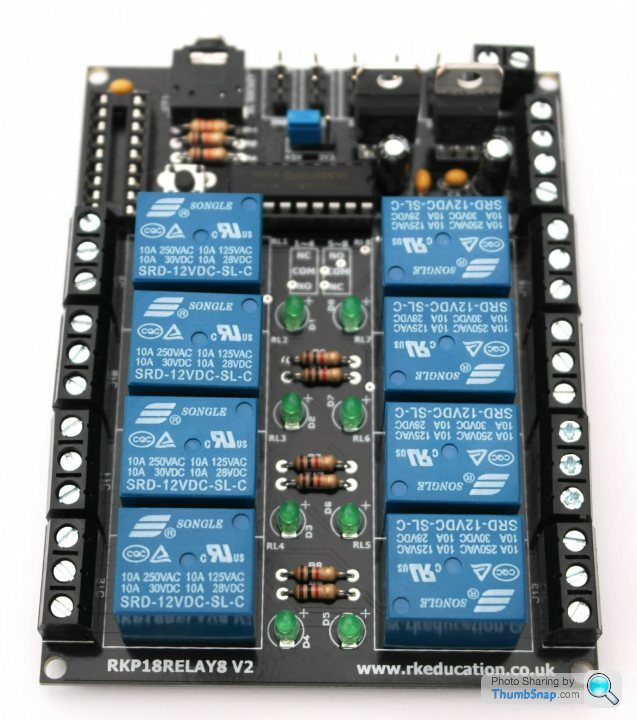
Juddder said:
The challenge we have here is that we have the same inputs and outputs as the original control boxes have, so nothing cleverer like being able to sense the amount of strain on the motor or whether the door latch is fully latched or lot. The mechanisms are actually quite simple in that they simply pulse the door latch release, drop the window and hope that you manage to open the door in time
The reed switch must also be an input to tell it to put the window up when the door is shut too? At the moment it seems a bit dodgy and seems to work something like:- Press door open button
-- Lower window to microswitch level
-- Activate latch solenoid
- Close door
-- If reed switch activates
--- Raise window
The problem happens when the reed switch activates and the door doesn't quite latch. The window goes up as soon as the reed switch activates and I've had people yank open the door to try closing it again with the window up in side the A pillar trim which then snaps bits of it off. Fiddling with the reed switch position can help but it's always a problem. I'm thinking that we could add a simple timer and recheck of the reed switch:
- Close door
-- If reed switch activates
--- Wait for n seconds
--- If reed switch still indicates door is shut
Raise window
Jabbah said:
I'm thinking that we could add a simple timer and recheck of the reed switch:
- Close door
-- If reed switch activates
--- Wait for n seconds
--- If reed switch still indicates door is shut
Raise window
Going back through my notes I found this diagram which shows we actually have a - Close door
-- If reed switch activates
--- Wait for n seconds
--- If reed switch still indicates door is shut
Raise window
Therefore we can probably easily do as you suggest above as we can track the door
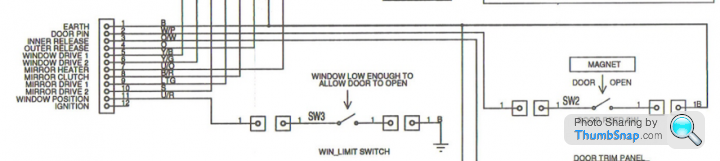
If you look at the original TVR wiring diagrams they use the window reed switch as an indicator that the window is low enough to open the door
Edited by Juddder on Monday 27th June 12:19
Juddder said:
Jabbah said:
I'm thinking that we could add a simple timer and recheck of the reed switch:
- Close door
-- If reed switch activates
--- Wait for n seconds
--- If reed switch still indicates door is shut
Raise window
Going back through my notes I found this diagram which shows we actually have a reed switch on the bottom of each door as well as the one tracking the window- Close door
-- If reed switch activates
--- Wait for n seconds
--- If reed switch still indicates door is shut
Raise window
Therefore we can probably easily do as you suggest above as we can track the door reed switch and then the window switch as needed
If you look at the original TVR wiring diagrams they use the window reed switch as an indicator that the window is low enough to open the door
If the reed switch activates when the door is not fully closed, the
One handy improvement you could make would be to drop the window (if necessary) when the reed switch opens, eg when you pull the red handle. It might not drop fast enough to prevent contact with the trim but one could at least restrain the door as it opens and window drops.
Edited by FarmyardPants on Monday 27th June 12:54
FarmyardPants said:
The window limit switch is a microswitch operated by the window
Yes - typing too fast too early in the morning 
The switch in the door for tracking whether the window is down or up is a microswitch with an extra long closer on it - the same as used in modern arcade joysticks
If I remember correctly from replacing the wiring harness in my drivers door it looks like this, but might have the contacts on the bottom
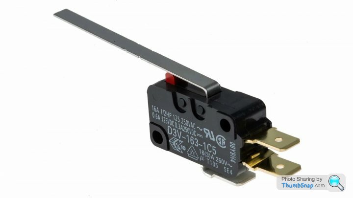
The bottom of the door switch has the magnet glued into the body of the car where the door closes - I didn't play with the switch actually in the bottom of the door, but good to hear that that can be moved if needed
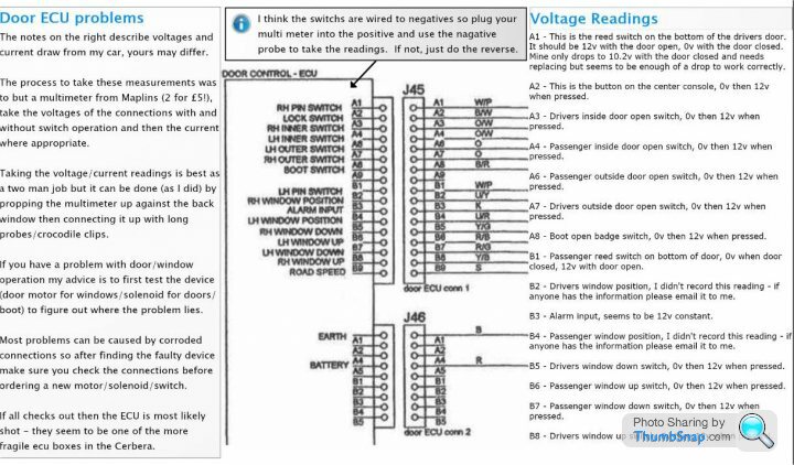
Door open, door closed magnetic switch is pin A1 and B1 on the door control box...
Seeing as mine stopped working due to dirty plugs
Useful thread with details and volts
https://www.pistonheads.com/gassing/topic.asp?h=0&...
Seeing as mine stopped working due to dirty plugs
Useful thread with details and volts
https://www.pistonheads.com/gassing/topic.asp?h=0&...
From non-working car to working car
TVR Cerbera Steering ECU Control Box: Prototype replacement first test
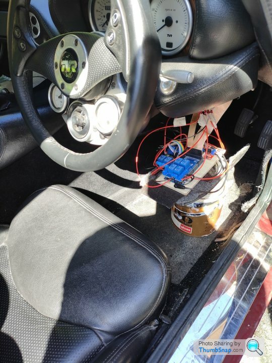
TVR Cerbera Steering ECU Control Box: Prototype replacement first test
Edited by Juddder on Saturday 27th August 15:39
Byker28i said:
Brilliant stuff
Thanks guys - always nice to have encouragement and really great to be finally making progress The original problem of the fuse box is now fixed with that firmly back in place with the original nut re-masticked back to the fibreglass body and the original bolt holding it firmly back in place
The car starts and drives perfectly, it's just the blown Steering Wheel ECU and the Door ECU that are the last problems to fix
This prototype in it's next version will replace the Steering Wheel ECU with a low profile plug-and-play boxed unit that can just be connected to the car as we've proven in the video above that the code and the concept works
The Door ECU I'm going to send to Paul Smith, as even though I have most of the working of the code for a replacement unit, in terms of complexity it's much harder than the SW ECU which is really just an on-off state machine most of the time
The only clever parts this unit (and it's emulator replacement do) is to switch the output which is turned on for the Wiper input and the Lights input as these switch modes based on the number of times the button is pressed
Also, the original SW ECU has a direct route for the Emergency button simply connecting the button to the output as I guess by law this has to work even when the car is turned off so I will need to add some wiring to do that
I'll add an update as I get the right box for the SW ECU and start building in the components :-)
Update:
As I'm putting the car all back together now that Paul Smith has repaired the Door Control Box and the Steering Wheel Control Box (Thanks Paul!), I've been documenting some of the other Control Boxes that blew so that I know how they work for the future
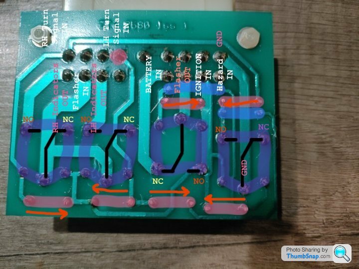
Here's a pretty complete documented PCB diagram of the Indicator Control Box which I had to replace a blown diode in
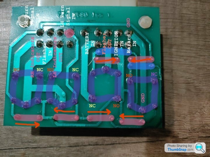
NC = Normally Closed side of Relay
NO = Normally Open side of Relay
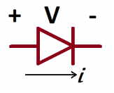
Arrows indicate flow of current in Diodes which goes from the Anode (+) to the Cathode (-)
The inputs are in White and the outputs in Pink and I did a quick how to test to show how it works which I thought might be interesting to share
Testing the indicators
and testing the hazard lights
and here's the final pinout for reference with INPUTs and OUTPUTs labelled
1. Indicator Control Box (J55)
| A1 A2 A3 A4 | | A6 A7 A8 A9 |
B1 B2 B3 B4 | B5 | B6 B7 B8 B9
A1 - RH Indicators OUTPUT (G/W)
A2 - Flasher INPUT (LTG/N)
A3 - LH Indicators OUTPUT (O/R)
A4 - N/C
-
A6 - Ignition INPUT (G)
A7 - Flasher Power OUTPUT (G/Y)
A8 - Battery INPUT (R)
A9 - Hazard Signal INPUT (N/B)
B1 - RH Turn Signal INPUT (G/W)
B2 - N/C
B3 - N/C
B4 - LH Turn Signal INPUT (G/R)
B5 - N/C
B6 - N/C
B7 - N/C
B8 - N/C
B9 - Earth INPUT (B)
and this is how the relays are setup to switch with power from NC to NO
As I'm putting the car all back together now that Paul Smith has repaired the Door Control Box and the Steering Wheel Control Box (Thanks Paul!), I've been documenting some of the other Control Boxes that blew so that I know how they work for the future
Here's a pretty complete documented PCB diagram of the Indicator Control Box which I had to replace a blown diode in
NC = Normally Closed side of Relay
NO = Normally Open side of Relay
Arrows indicate flow of current in Diodes which goes from the Anode (+) to the Cathode (-)
The inputs are in White and the outputs in Pink and I did a quick how to test to show how it works which I thought might be interesting to share
Testing the indicators
and testing the hazard lights
and here's the final pinout for reference with INPUTs and OUTPUTs labelled
1. Indicator Control Box (J55)
| A1 A2 A3 A4 | | A6 A7 A8 A9 |
B1 B2 B3 B4 | B5 | B6 B7 B8 B9
A1 - RH Indicators OUTPUT (G/W)
A2 - Flasher INPUT (LTG/N)
A3 - LH Indicators OUTPUT (O/R)
A4 - N/C
-
A6 - Ignition INPUT (G)
A7 - Flasher Power OUTPUT (G/Y)
A8 - Battery INPUT (R)
A9 - Hazard Signal INPUT (N/B)
B1 - RH Turn Signal INPUT (G/W)
B2 - N/C
B3 - N/C
B4 - LH Turn Signal INPUT (G/R)
B5 - N/C
B6 - N/C
B7 - N/C
B8 - N/C
B9 - Earth INPUT (B)
and this is how the relays are setup to switch with power from NC to NO
Edited by Juddder on Thursday 17th November 12:53
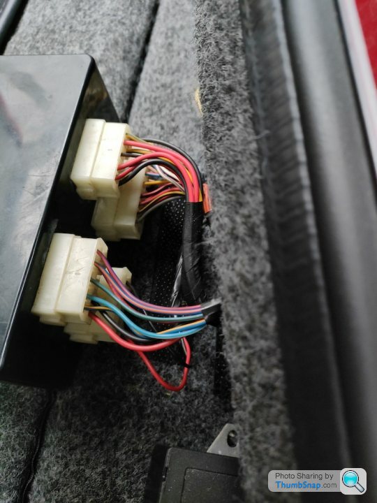
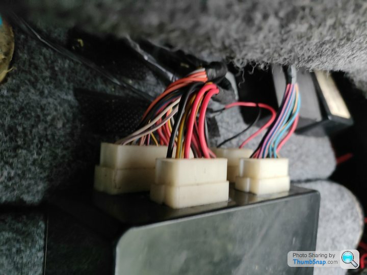
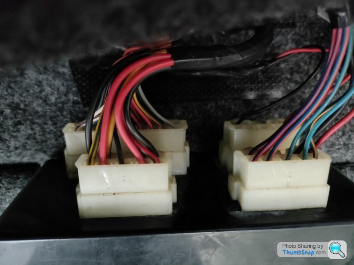
The repaired Door Control Box is reconnected and finally the door locks, boot lock and windows are working again 
As I had to look up the original disconnection of the leads photos on my phone as 3 of the 4 connectors on the Door Control Box are exactly the same size (thanks TVR) here's the photos for reference and also my documentation on the pinouts
Note: You can do some serious damage to the PCB if you connect these incorrectly as, for example, pin A5 on J47 is +12V whereas pin A5 on J48 is GND and both are exactly the same size plugs
3. Door Control - ECU

[Back of box]

J47 J48
J46 -J45-

(screws and bottom)

(J45) door ECU conn 1

[Front]

B1 B2 B3 B4 B5 B6 B7 B8 B9
A1 A2 A3 A4 -- A6 A7 A8 A9

A1 - RH Pin Switch (W/P)
A2 - Lock Switch (S/W)
A3 - RH Inner Switch (O/W)
A4 - LH Inner Switch (O/W)
-
A6 - LH Outer Switch (O)
A7 - RH Outer Switch (O)
A8 - Boot Switch (B/R)
A9 - N/C
B1 - LH Pin Switch (W/P)
B2 - RH Window Position (U/V)
B3 - Alarm Input (K)
B4 - LH Window Position ?
B5 - RH Window Down (Y/G)
B6 - LH Window Up (R/B)
B7 - LH Window Down (R/G)
B8 - RH Window Up (Y/B)
B9 - Road Speed (S)

(J46) door ECU conn 2

[Front]

B1 B2 B3 B4 B5
A1 A2 -- A4 A5

A1 - Earth (B)
A2 - N/C
-
A4 - Battery (R)
A5 - N/C
B1 - N/C
B2 - N/C
B3 - N/C
B4 - N/C
B5 - N/C

(J47) door ECU conn 3

[Front]

B1 B2 B3 B4 B5
A1 A2 -- A4 A5

A1 - Boot Lock Drive (R/V) - Schrack T7NS5D4-12
A2 - Battery (R)
-
A4 - Earth (B)
A5 - Battery (R)
B1 - Interior Lamp (P/R) - Schrack T7NS5D4-12
B2 - RH Lock Drive 1 (U/O) - Schrack T7NS5D4-12
B3 - RH Lock Drive 2 (U/G) - Schrack T7NS5D4-12
B4 - LH Lock Drive 1 (U/W) - Schrack T7NS5D4-12
B5 - LH Lock Drive 2 (U/V) - Schrack T7NS5D4-12

(J48) door ECU conn 4

[Front]

B1 B2 B3 B4 B5
A1 A2 -- A4 A5

A1 - Earth (B)
A2 - RH Window 1 (Y/B) - RTD14012
-
A4 - LH Window 1 (R/G) - RTD14012
A5 - Earth (B)
B1 - RH Window 2 (Y/G) - RTD14012
B2 - Battery (R)
B3 - LED Drive
B4 - Battery (R)
B5 - LH Window 2 (R/G) - RTD14012
BTW has anyone worked on the Windscreen Wiper washer jets power system at all?
When I prime the car, the Wiper jet washer motor is running continually so I wonder if the powering circuit also got affected on the way
The Steering Control Box is only triggering other Control Boxes to run as far as I can tell as it only has lower power circuits, but I can't see on the wiring diagram where any of the rear control boxes are interacting with the Windscreen Wiper washer jet system in any way
Juddder said:
When I prime the car, the Wiper jet washer motor is running continually so I wonder if the powering circuit also got affected on the way
The Steering Control Box is only triggering other Control Boxes to run as far as I can tell as it only has lower power circuits, but I can't see on the wiring diagram where any of the rear control boxes are interacting with the Windscreen Wiper washer jet system in any way
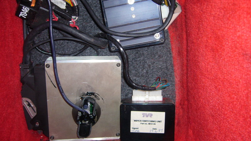
So I did some more studying of the engine wiring diagrams and it turns out there _is_ another Control Box called the Wiper Control - ECU on the Main Harness Wiring DiagramThe Steering Control Box is only triggering other Control Boxes to run as far as I can tell as it only has lower power circuits, but I can't see on the wiring diagram where any of the rear control boxes are interacting with the Windscreen Wiper washer jet system in any way
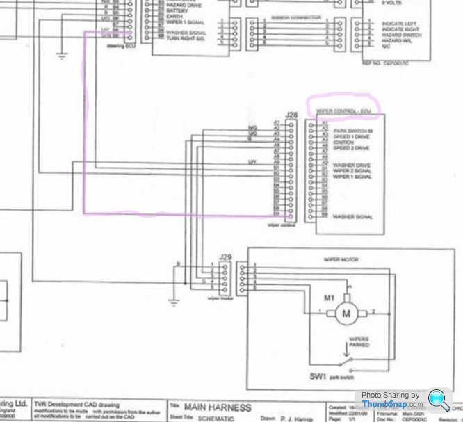
So I did a bit of research and according to this thread it is in the passenger footwell where the ECU is stashed
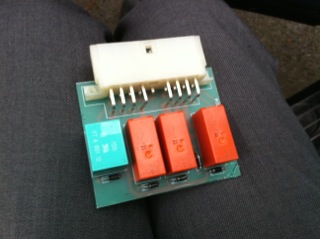
From this thread there are some images of the PCB showing that it has 4 relays and a number of diodes, a bit like the Indicator Control Box, so I'm predicting that one of those diodes got fried in the same way as the Indicator Control Box did when the power reverse spike happened
I'll take that one out when I'm next over with the car and see what it looks like but in the meantime I have managed to buy a spare one from eBay
Edited by Juddder on Saturday 19th November 17:25
Juddder said:
Juddder said:
When I prime the car, the Wiper jet washer motor is running continually so I wonder if the powering circuit also got affected on the way
The Steering Control Box is only triggering other Control Boxes to run as far as I can tell as it only has lower power circuits, but I can't see on the wiring diagram where any of the rear control boxes are interacting with the Windscreen Wiper washer jet system in any way
So I did some more studying of the engine wiring diagrams and it turns out there _is_ another Control Box called the Wiper Control - ECU on the Main Harness Wiring DiagramThe Steering Control Box is only triggering other Control Boxes to run as far as I can tell as it only has lower power circuits, but I can't see on the wiring diagram where any of the rear control boxes are interacting with the Windscreen Wiper washer jet system in any way
So I did a bit of research and according to this thread it is in the passenger footwell where the ECU is stashed
From this thread there are some images of the PCB showing that it has 4 relays and a number of diodes, a bit like the Indicator Control Box, so I'm predicting that one of those diodes got fried in the same way as the Indicator Control Box did when the power reverse spike happened
I'll take that one out when I'm next over with the car and see what it looks like but in the meantime I have managed to buy a spare one from eBay
Edited by Juddder on Saturday 19th November 17:25
Gassing Station | Cerbera | Top of Page | What's New | My Stuff