Light control box modification - pic
Discussion


tofts said:
I'm sorry to have to say, but the above is not great advice! Most definitely not the correct way to do it and in actual fact can be a fire risk.
On the back of the module there is a small blue/white, and small blue/red, get any diode you can lay your hand on (1n4007 is standard but pretty much any diode will work) and intercept the two.
Cathode (striped end) on blue/red, anode (clear end) on blue/white.
Its done like that for a reason, please don't change it, and don't do it any other way and it could trash whats left of your already trashed plug and board header (change these too, please!). The fact your fog lights are on as well is a cause for concern and proves my thought that current is being fed elsewhere through the board in an incorrect fashion!
As for the dim-dip issue on HIDs - on the dim-dip control unit, there is a thick red wire and a thick blue/red wire, join these together, take out the DIM Dip control unit and DIM DIP ecu completely and IGNORE all of the other wires, job done forever, safely. The 7v output is actually not 7v, but a Pulse width signal switching around 1000 times a second, you need an oscilloscope to see it, and will work perfectly well with LEDs.
If anyone is confused as to what to do or how to do either of the above SAFELY - RING ME (074OO 889449)
You actually have a very early model control unit, Luckyone (the name is actually ironic, as you're a luckone this hasn't caught fire). the later cars are very different, and there is a different method for doing that which involves putting the diode directly on the board, again, if unsure. ring me, please.
Jody
I regretted my username a few weeks after choosing it, I never gave it any thought that I'd be stuck with it 15 odd years later! I really hate it now, but luckily nothing has blown up yet. On the back of the module there is a small blue/white, and small blue/red, get any diode you can lay your hand on (1n4007 is standard but pretty much any diode will work) and intercept the two.
Cathode (striped end) on blue/red, anode (clear end) on blue/white.
Its done like that for a reason, please don't change it, and don't do it any other way and it could trash whats left of your already trashed plug and board header (change these too, please!). The fact your fog lights are on as well is a cause for concern and proves my thought that current is being fed elsewhere through the board in an incorrect fashion!
As for the dim-dip issue on HIDs - on the dim-dip control unit, there is a thick red wire and a thick blue/red wire, join these together, take out the DIM Dip control unit and DIM DIP ecu completely and IGNORE all of the other wires, job done forever, safely. The 7v output is actually not 7v, but a Pulse width signal switching around 1000 times a second, you need an oscilloscope to see it, and will work perfectly well with LEDs.
If anyone is confused as to what to do or how to do either of the above SAFELY - RING ME (074OO 889449)
You actually have a very early model control unit, Luckyone (the name is actually ironic, as you're a luckone this hasn't caught fire). the later cars are very different, and there is a different method for doing that which involves putting the diode directly on the board, again, if unsure. ring me, please.
Jody
Edited by tofts on Wednesday 20th December 15:50
I'm Andyrt on every other forum I've joined since.
As you said my control box is different so the pics aren't much use to me unfortunately.
You mentioned "On the back of the module there is a small blue/white, and small blue/red"
I assume you are talking about wires there?!
So assuming its the wires you are talking about it seem very much to me that you're using the main beams (blue/white) to power the dips (blue/red) via the diode. That has to be more of a fire risk than what I've done. You are asking the already inadequate power cable & connection for mains to give all the power for the dips as well as the main beams.
Or maybe doing that causes the dip relay to switch back on. If that is the case it has the same effect as doing what I've done.
Maybe the later boxes are different & only had one good power supply, but my earlier box had two power cables, one for the dips & one for the mains.
The fogs stay on, not because of some dodgy back feed but because the power out of the dips track (blue/white wire) is connected directly to the fogs relay (no diodes in that track so would with your method too) as an override to the on off button to stop the fog being able to come on without the dip lights also being on.
Sorry I was not very clear saying fogs stay on, they stay on only if they are actually turned on from the dash switch.
Before if they were turned on with the dash switch (& were actually on because the dips were on) they actually went off when the main beam was activated purely because the main beams activated that relay I've bridged, with that relay on the power to the dips & the activation to the fogs relay was cut.
As the boards shown are so different to my board I've no idea what the placement of your diode does. If its there just to stop the relay that cuts the power to the dips activating, it seems to me that is the same as just bringing the connections as I did.
I'm no electronics expert, please explain why what I've done is such a fire risk. I'm not trying to be funny I'm genuinely interested. It more interesting for everyone else to see on here than me ringing you, but thanks for the number.
I have bridged the bad power connections, power out first then after I checked with my thermal camera the power in too, as I could see that connection was hot. That was before I'd done anything thing to keep the dips on with the mains. I checked it again aftet my mod & after leaving it to cook for a while with my thermal camera & it was no hotter running the dips & mains together.
As I mentioned in my other thread the power in cable for the dips is really a bit too thin but its lasted 20 odd years so far! I have lower power LEDs hanging off it now too.
mk1fan said:
I assume that both these ecu boxes deal with the twin 70mm Helka units rather than the single 9-inch units of the early Cerbs.
My box was for the early single unit, (98 car built in 97) hence the need to modify it. The single light unit cannot have both dips & main beam on at the same time or it will overheat the single bulb. I converted to the twin Hella units many years ago but am only just getting round to changing the electrics so both the dip & main Hella units can be on together.
I shouldn't think there is a need to modify later boxes for car that came with the twin pods. Then again this is TVR we're talking about!
It's a good point really I don't know why the other boxes in this thread are different....
Luckyone said:
tofts said:
I'm sorry to have to say, but the above is not great advice! Most definitely not the correct way to do it and in actual fact can be a fire risk.
On the back of the module there is a small blue/white, and small blue/red, get any diode you can lay your hand on (1n4007 is standard but pretty much any diode will work) and intercept the two.
Cathode (striped end) on blue/red, anode (clear end) on blue/white.
Its done like that for a reason, please don't change it, and don't do it any other way and it could trash whats left of your already trashed plug and board header (change these too, please!). The fact your fog lights are on as well is a cause for concern and proves my thought that current is being fed elsewhere through the board in an incorrect fashion!
As for the dim-dip issue on HIDs - on the dim-dip control unit, there is a thick red wire and a thick blue/red wire, join these together, take out the DIM Dip control unit and DIM DIP ecu completely and IGNORE all of the other wires, job done forever, safely. The 7v output is actually not 7v, but a Pulse width signal switching around 1000 times a second, you need an oscilloscope to see it, and will work perfectly well with LEDs.
If anyone is confused as to what to do or how to do either of the above SAFELY - RING ME (074OO 889449)
You actually have a very early model control unit, Luckyone (the name is actually ironic, as you're a luckone this hasn't caught fire). the later cars are very different, and there is a different method for doing that which involves putting the diode directly on the board, again, if unsure. ring me, please.
Jody
I regretted my username a few weeks after choosing it, I never gave it any thought that I'd be stuck with it 15 odd years later! I really hate it now, but luckily nothing has blown up yet. On the back of the module there is a small blue/white, and small blue/red, get any diode you can lay your hand on (1n4007 is standard but pretty much any diode will work) and intercept the two.
Cathode (striped end) on blue/red, anode (clear end) on blue/white.
Its done like that for a reason, please don't change it, and don't do it any other way and it could trash whats left of your already trashed plug and board header (change these too, please!). The fact your fog lights are on as well is a cause for concern and proves my thought that current is being fed elsewhere through the board in an incorrect fashion!
As for the dim-dip issue on HIDs - on the dim-dip control unit, there is a thick red wire and a thick blue/red wire, join these together, take out the DIM Dip control unit and DIM DIP ecu completely and IGNORE all of the other wires, job done forever, safely. The 7v output is actually not 7v, but a Pulse width signal switching around 1000 times a second, you need an oscilloscope to see it, and will work perfectly well with LEDs.
If anyone is confused as to what to do or how to do either of the above SAFELY - RING ME (074OO 889449)
You actually have a very early model control unit, Luckyone (the name is actually ironic, as you're a luckone this hasn't caught fire). the later cars are very different, and there is a different method for doing that which involves putting the diode directly on the board, again, if unsure. ring me, please.
Jody
Edited by tofts on Wednesday 20th December 15:50
I'm Andyrt on every other forum I've joined since.
As you said my control box is different so the pics aren't much use to me unfortunately.
You mentioned "On the back of the module there is a small blue/white, and small blue/red"
I assume you are talking about wires there?!
So assuming its the wires you are talking about it seem very much to me that you're using the main beams (blue/white) to power the dips (blue/red) via the diode. That has to be more of a fire risk than what I've done. You are asking the already inadequate power cable & connection for mains to give all the power for the dips as well as the main beams.
Or maybe doing that causes the dip relay to switch back on. If that is the case it has the same effect as doing what I've done.
Maybe the later boxes are different & only had one good power supply, but my earlier box had two power cables, one for the dips & one for the mains.
The fogs stay on, not because of some dodgy back feed but because the power out of the dips track (blue/white wire) is connected directly to the fogs relay (no diodes in that track so would with your method too) as an override to the on off button to stop the fog being able to come on without the dip lights also being on.
Sorry I was not very clear saying fogs stay on, they stay on only if they are actually turned on from the dash switch.
Before if they were turned on with the dash switch (& were actually on because the dips were on) they actually went off when the main beam was activated purely because the main beams activated that relay I've bridged, with that relay on the power to the dips & the activation to the fogs relay was cut.
As the boards shown are so different to my board I've no idea what the placement of your diode does. If its there just to stop the relay that cuts the power to the dips activating, it seems to me that is the same as just bringing the connections as I did.
I'm no electronics expert, please explain why what I've done is such a fire risk. I'm not trying to be funny I'm genuinely interested. It more interesting for everyone else to see on here than me ringing you, but thanks for the number.
I have bridged the bad power connections, power out first then after I checked with my thermal camera the power in too, as I could see that connection was hot. That was before I'd done anything thing to keep the dips on with the mains. I checked it again aftet my mod & after leaving it to cook for a while with my thermal camera & it was no hotter running the dips & mains together.
As I mentioned in my other thread the power in cable for the dips is really a bit too thin but its lasted 20 odd years so far! I have lower power LEDs hanging off it now too.
Regarding headlight wiring, as long as any diodes that you fit are not load carrying you can do whatever takes your fancy. If you are fitting diodes in series with a load carrying circuit you are making a big mistake due to diodes creating a volt drop.
Electronic circuits are designed to compensate for diodes volt drops. A cars power supply voltage isn't increased to compensate for a diodes volt drop
I am surprised that nobody has mentioned Dim Dip MOT Regulations, I am almost certain that Dim Dip isn't part of the MOT requirements
The Dim Dip Unit fitted to a Cerbera can be thrown away
What do you think?
Edited by Penelope Stoppedit on Friday 22 December 12:06
Dim Dip [legal] requirement was very short lived and went the way of the Dodo long before the Cerb was announced.
It does have a practical use on TVRs given how low they are and the positioning of side lights generally places them where the 'Average Motorist' isn't looking but a set of LED side lights gives a decent enough boost in output to compensate for this yet still be 'dim' enough to comply as side lights.
It does have a practical use on TVRs given how low they are and the positioning of side lights generally places them where the 'Average Motorist' isn't looking but a set of LED side lights gives a decent enough boost in output to compensate for this yet still be 'dim' enough to comply as side lights.
The early boxes are different, but the principals are the same regardless
just to reiterate and those that do not know, I repair these units as part of my Job and those may recognize me from the facebook side of things.
Yes I do mean wires, luckyone. Don't sweat the name, I never think about it anyway, it just made me chuckle when I was writing the last post!
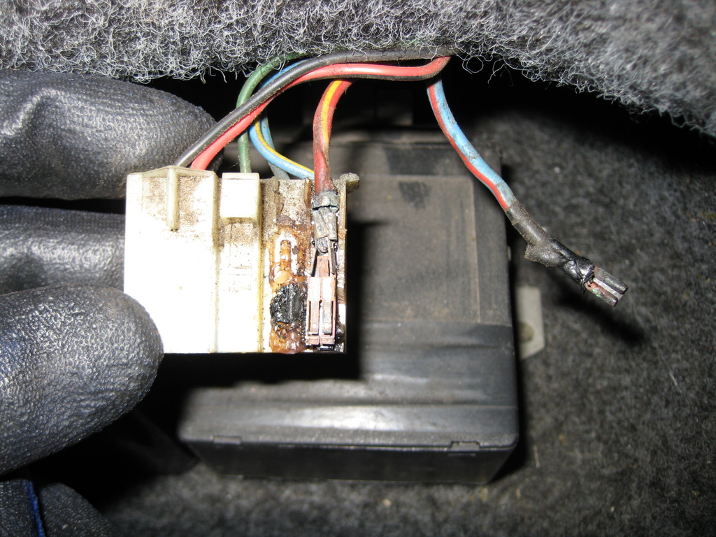
Anyhow, the wires I mention, the small wires, are merely control wires that energize the relays and take about 150ma to power the relays, thus these wires take almost no current so ever. By bridging the contacts the way that you have, the full load of each bulb will be taken through that blob of solder and the tracks in a fashion that it was never designed for as you have bridged across the backs of the outputs of the relays. I have a LOT of horror photos of the lack of current carrying capacity of the tracks on these boards and thus is not something I would recommend. Whilst it may work, it's not necessarily right, or safe.
If you use the control wires, when you press the button it will use the small output from the "steering wheel control unit" to power both relays at the same time, this circuit is more than capable of handling the extra load of the other relay, so about 300ma in total. The reason the diode is necessary is that if you were just to connect the wires together, then turning the dip beam on will also turn the main beam on at the same time. This is why any diode will work, even signal diodes will work as they will usually be able to sink a current of 500ma, and worse case if they don't is they blow open circuit. No harm done.
I perform my pictured modification on almost all of the control units and if you actually look even more carefully you will see that the extra diode is actually powering another transistor and not the relay directly, and so the load across the diode is about nothing and thus zero strain to the existing circuitry.
As for the dim-dip, it is not an MOT requirement and can be got rid of completely as per my last post. YOU DO NOT NEED ANY RELAYS TO GET RID OF IT, just join the big RED wire and big BLUE/WHITE on the dim-dip control together and throw BOTH of the dim-dip control, and dim-dip ECU in your toolbox somewhere.
jody
just to reiterate and those that do not know, I repair these units as part of my Job and those may recognize me from the facebook side of things.
Yes I do mean wires, luckyone. Don't sweat the name, I never think about it anyway, it just made me chuckle when I was writing the last post!
Anyhow, the wires I mention, the small wires, are merely control wires that energize the relays and take about 150ma to power the relays, thus these wires take almost no current so ever. By bridging the contacts the way that you have, the full load of each bulb will be taken through that blob of solder and the tracks in a fashion that it was never designed for as you have bridged across the backs of the outputs of the relays. I have a LOT of horror photos of the lack of current carrying capacity of the tracks on these boards and thus is not something I would recommend. Whilst it may work, it's not necessarily right, or safe.
If you use the control wires, when you press the button it will use the small output from the "steering wheel control unit" to power both relays at the same time, this circuit is more than capable of handling the extra load of the other relay, so about 300ma in total. The reason the diode is necessary is that if you were just to connect the wires together, then turning the dip beam on will also turn the main beam on at the same time. This is why any diode will work, even signal diodes will work as they will usually be able to sink a current of 500ma, and worse case if they don't is they blow open circuit. No harm done.
I perform my pictured modification on almost all of the control units and if you actually look even more carefully you will see that the extra diode is actually powering another transistor and not the relay directly, and so the load across the diode is about nothing and thus zero strain to the existing circuitry.
As for the dim-dip, it is not an MOT requirement and can be got rid of completely as per my last post. YOU DO NOT NEED ANY RELAYS TO GET RID OF IT, just join the big RED wire and big BLUE/WHITE on the dim-dip control together and throw BOTH of the dim-dip control, and dim-dip ECU in your toolbox somewhere.
jody
Edited by tofts on Friday 22 December 11:41
mk1fan]Dim Dip [legal said:
requirement was very short lived and went the way of the Dodo long before the Cerb was announced.
It does have a practical use on TVRs given how low they are and the positioning of side lights generally places them where the 'Average Motorist' isn't looking but a set of LED side lights gives a decent enough boost in output to compensate for this yet still be 'dim' enough to comply as side lights.
Interesting, perhaps it would be good to fit and wire some LED's as day driving lights and throw the Dim Dip Unit in the binIt does have a practical use on TVRs given how low they are and the positioning of side lights generally places them where the 'Average Motorist' isn't looking but a set of LED side lights gives a decent enough boost in output to compensate for this yet still be 'dim' enough to comply as side lights.
Penelope Stoppedit said:
Luckyone, do you know that you can change your username here at PH?
Thanks, yes I did know, I remember Ash changing his name to SXS, what ever happened to him? I thought about changing it a long time ago but figured people will at least remember it!
I really was cursing it though as I was pulling the engine out again after just putting it back after my body off rebuild having taken some advice from a pro AJP engine builder that had some nasty results. So I'm quite happy (& feeling a little lucky) to be fiddling with little things like this now its actually running nicely

tofts said:
The early boxes are different, but the principals are the same regardless
just to reiterate and those that do not know, I repair these units as part of my Job and those may recognize me from the facebook side of things.
Yes I do mean wires, luckyone. Don't sweat the name, I never think about it anyway, it just made me chuckle when I was writing the last post!
Anyhow, the wires I mention, the small wires, are merely control wires that energize the relays and take about 150ma to power the relays, thus these wires take almost no current so ever. By bridging the contacts the way that you have, the full load of each bulb will be taken through that blob of solder and the tracks in a fashion that it was never designed for as you have bridged across the backs of the outputs of the relays. I have a LOT of horror photos of the lack of current carrying capacity of the tracks on these boards and thus is not something I would recommend. Whilst it may work, it's not necessarily right, or safe.
If you use the control wires, when you press the button it will use the small output from the "steering wheel control unit" to power both relays at the same time, this circuit is more than capable of handling the extra load of the other relay, so about 300ma in total. The reason the diode is necessary is that if you were just to connect the wires together, then turning the dip beam on will also turn the main beam on at the same time. This is why any diode will work, even signal diodes will work as they will usually be able to sink a current of 500ma, and worse case if they don't is they blow open circuit. No harm done.
I perform my pictured modification on almost all of the control units and if you actually look even more carefully you will see that the extra diode is actually powering another transistor and not the relay directly, and so the load across the diode is about nothing and thus zero strain to the existing circuitry.
As for the dim-dip, it is not an MOT requirement and can be got rid of completely as per my last post. YOU DO NOT NEED ANY RELAYS TO GET RID OF IT, just join the big RED wire and big BLUE/WHITE on the dim-dip control together and throw BOTH of the dim-dip control, and dim-dip ECU in your toolbox somewhere.
jody
Ah thanks Jody, that make perfect sense now & is exactly what I was trying to achieve! just to reiterate and those that do not know, I repair these units as part of my Job and those may recognize me from the facebook side of things.
Yes I do mean wires, luckyone. Don't sweat the name, I never think about it anyway, it just made me chuckle when I was writing the last post!
Anyhow, the wires I mention, the small wires, are merely control wires that energize the relays and take about 150ma to power the relays, thus these wires take almost no current so ever. By bridging the contacts the way that you have, the full load of each bulb will be taken through that blob of solder and the tracks in a fashion that it was never designed for as you have bridged across the backs of the outputs of the relays. I have a LOT of horror photos of the lack of current carrying capacity of the tracks on these boards and thus is not something I would recommend. Whilst it may work, it's not necessarily right, or safe.
If you use the control wires, when you press the button it will use the small output from the "steering wheel control unit" to power both relays at the same time, this circuit is more than capable of handling the extra load of the other relay, so about 300ma in total. The reason the diode is necessary is that if you were just to connect the wires together, then turning the dip beam on will also turn the main beam on at the same time. This is why any diode will work, even signal diodes will work as they will usually be able to sink a current of 500ma, and worse case if they don't is they blow open circuit. No harm done.
I perform my pictured modification on almost all of the control units and if you actually look even more carefully you will see that the extra diode is actually powering another transistor and not the relay directly, and so the load across the diode is about nothing and thus zero strain to the existing circuitry.
As for the dim-dip, it is not an MOT requirement and can be got rid of completely as per my last post. YOU DO NOT NEED ANY RELAYS TO GET RID OF IT, just join the big RED wire and big BLUE/WHITE on the dim-dip control together and throw BOTH of the dim-dip control, and dim-dip ECU in your toolbox somewhere.
jody
It's a shame TVR used the same colour combo of wires for different things! I guess it is keeping to the same circuit kind of makes sense though. I just assumed you were talking about the main power wires of the same colour that go into the same box.
I tested those small signal input wires & both the mains & dips seem to work by pulling the relay to ground (if that's the right term), but the dip beam input seemed to go high when the mains were tuned on, putting the diode in would use the mains signal to pull the dips signal to ground then? That to me sounds like it could damage the front control box, but I know nothing about the front control box...
You clearly know a lot more about these boxes than me, it just seemed safer to me to leave the signal wires well alone & bridge those relay connections. Yes you're right the big blobs of solder are taking all the current of my LEDs. But I'm not asking any track, wire or connector to do anything it wasn't already doing. Putting a diode in to make the relay stay off (so it can't kick in & break the current path) would mean exactly the same tracks were being used as my soldered job. If you or anyone else thinks my big blobs of solder can't carry as much current as the thin little tracks please say. I had an electronics teacher at collage who said you shouldn't solder speaker wires as the solder acted as a capacitor, I was never entirely sure I believed him...
As for dim dips I'm a "bit special" in that I put my side light bulbs into the main beam units, so when I put the dim dips on all 4 pods come on at roughly the same brightness level, I just like it like that. Also the LEDs are rather bright so (just as any car with HIDs will too), going over the brow of a hill or a sharp left hand bend will result in the on coming traffic getting the full beam in their face. I want to be able to run them at partial brightness if I don't actually need them to be able to see where I'm going my self.
I think its probably actually illegal to drive with just your dips on, but no one (apart from you lot now
 ) will ever know!
tofts said:
As for the dim-dip, it is not an MOT requirement and can be got rid of completely as per my last post. YOU DO NOT NEED ANY RELAYS TO GET RID OF IT, just join the big RED wire and big BLUE/WHITE on the dim-dip control together and throw BOTH of the dim-dip control, and dim-dip ECU in your toolbox somewhere.
jody
Thanks, just followed your advice because the connector had melted where the two high current wires are, and the headlights failedjody
Joined them and binned the Dim Dip Control box as you advised although colours were slightly different - red/yellow & blue/red
Should have done that years ago
ukkid35 said:
Thanks, just followed your advice because the connector had melted where the two high current wires are, and the headlights failed
Joined them and binned the Dim Dip Control box as you advised although colours were slightly different - red/yellow & blue/red
Should have done that years ago
Hey Paul and JodyJoined them and binned the Dim Dip Control box as you advised although colours were slightly different - red/yellow & blue/red
Should have done that years ago
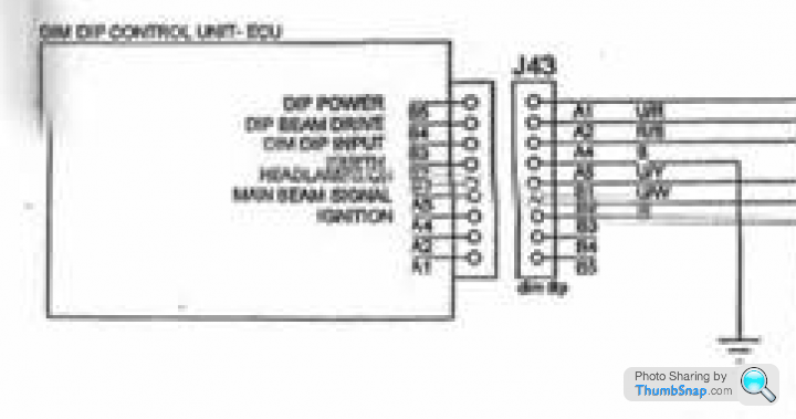
Just researching this for a. my own interest and b. with Paul's recent other headlight issues I've been looking in to all 3 Light ECU boxes, and I think Paul's wires actually do match the very blurry and badly labelled Rear Harness Part 1 wiring diagram as far as I can see
The unit side of the diagram for the Dim DIp Control Unit ECU is labelled back to front (A1 should be B5 etc. and vice verse) and there is no colour specified for A1 Dip Power, but if you go with your photo above A1 and A2 are the wires that have melted and therefore A1 is R/Y = Red / Yellow which then means the rest of the labelling is correct as A2 is U/R = Blue / Red which also matches your photo
Following the diagram labellings and your photo as far as I can tell the final labelling and colouring should be:
Dim Dip Control Unit ECU [J43]

A1 - Dip Power [LE A6] [?R/Y] Red / Yellow
A2 - Dip Beam Drive [U/R] Blue / Red
A3 - ---
A4 - Dim Dip Input [R/B] Red / Black
A5 - Earth [GND] [B]
B1 - Headlamps On [U/Y]
B2 - Main Beam Signal [U/W]
B3 - Ignition [LE A7] [G]
B4 -
B5 -
So with your modification that would be joining A1 - Dip Power with A2 - Dip Beam Drive to bypass the unit.
Jody's recommendation sounds potentially different as "just join the big RED wire and big BLUE/WHITE on the dim-dip control together" sounds like it is B2 - Main Beam Signal [U/W] to potentially A4 (??) Dim Dip Input or A2 - Dip Beam Drive [U/R] - Jody which wires were you thinking of for that one?
...and BTW does anyone have any better scans of these wiring diagrams?
Thanks Alex
Gassing Station | Cerbera | Top of Page | What's New | My Stuff