Engine rebuild
Discussion


4321go said:
So, onto the machining of the block.
You’ll recall that the bores were badly scored by the ceramic “sand” that had worked its way back up the header pipes from the cats:
As standard, the bores of the cast alloy blocks are plated with Nikasil, a nickel/ceramic coating that provides a hard finish for the piston rings to run against. Boring and re-plating/honing would result in oversize bores, and oversize pistons aren’t available. So the options were a new block, or a sleeved one. The latter would be a £2k saving and would result in a harder-wearing finish. There were no obvious advantages to having a new block for me, so we decided to machine the old one.
The steel liners came from L.A. Sleeve of Santa Fe, Ca. and are flanged. That is to say that for most of their length, they are a thin-walled steel tube, but towards the top, cylinder head-end, they are much thicker-walled. Therefore they are much more positively seated than a sleeve without a flange. The bores are rebored to the outside diameter of the sleeve, and then counter-bored to the diameter and depth of the flange, before the deck is skimmed flat. With the head torqued down the flange is pressed firmly into its seat. This isn’t my block, nor L.A. Sleeve liners, but I’m sure mine looked very similar:
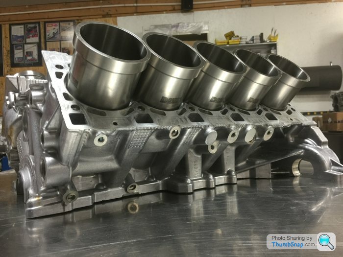
In the following pictures it appears that the bores have become Siamesed, and indeed they have, but only to the depth of the flange. Lower down, the alloy webs remain between the cylinders (and this IS my block):

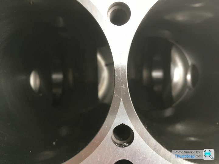
Lower down in the bores, the liners have “windage” holes drilled through them, and this is a convenient time to show you one of the numerous differences between the 5.0 and 5.2 litre blocks. (Remember that the two V10 units (Lambo’s 5 and Audi’s 5.2) were developed separately from related, but different, 4 and 4.2 litre V8s.)
Here is an end shot of a (later) 5.2 litre block:
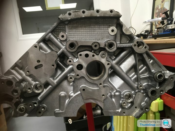
And my (earlier) 5.0 litre block
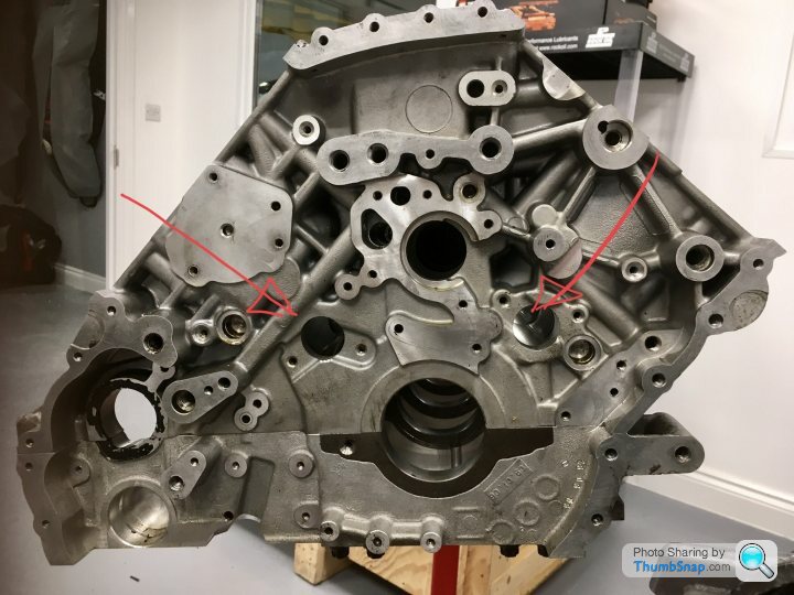
Note the two extra holes in the earlier block. These are the windage holes and pass through the lower end of each cylinder for the entire length of each bank. As the pistons thrash up and down, the air in the volumes below them is repeatedly being compressed and expanded. In the earlier engine, these pressure changes are alleviated and reduced by the air being allowed to pass from one bore to the next through the windage holes (in addition to it passing under the base of each bore). This extra alleviation of the pressure changes wasn’t needed in the later engines due to the increased efficiency of the oil scavenge pump fitted to the latter. Of much greater power (six chambers rather than three?) it can pump oil from the dry sump back to the oil tank at a much greater rate. Therefore the oil is less likely to become aerated in the short time that it spends under the thrashing pistons, and so there is less need to reduce the air pressure differences with the later oil pump.
Who knew? (Well, Ricky for one!)
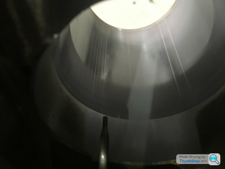
Anyway, here is one of the windage holes in a cylinder sleeve, as seen down one of the bores of my block:
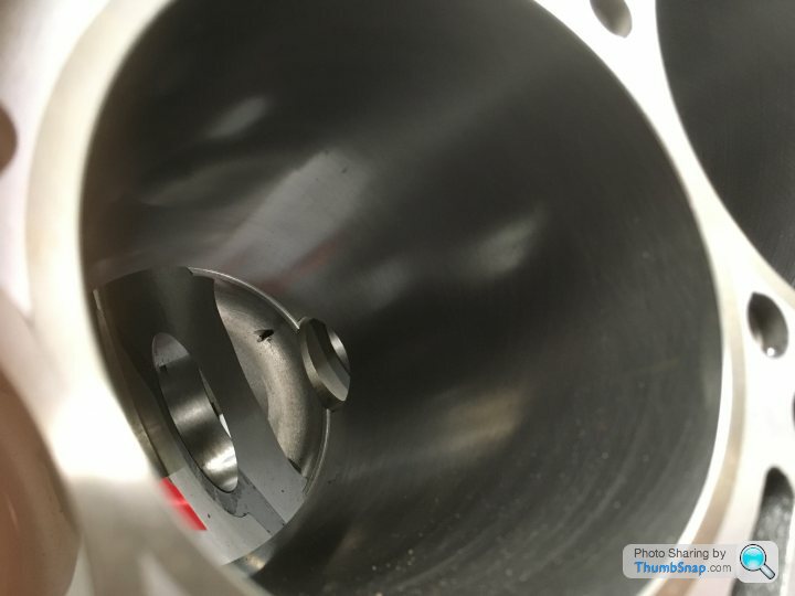
(I should add that all of the shots of my block were taken shortly after it arrived back from the machinist. Ricky had been measuring up for the crank shell sizes and then it was going into his parts cleaning tank for several hours. That should have shifted not only the swarf in the galleries, but the dead flies too!!)
With the sleeves machined into place, they then have to be honed to size and shape. And it was this process that led to the biggest delay in the machining process. Because, in all of the photos of my block above, the bore is the wrong shape!!
When you torque down the cylinder head onto the block, it distorts the block itself. (And indeed, how the block is distorted depends on whether the head is held down by studs or bolts, the former squashing the top of the block, the latter the bottom.) As you look at the photos above, the bores are not round! They will only become so again when the cylinder heads are torqued down onto them. Therefore, before the cylinder liners can be honed to size, the block has to be distorted in exactly the same way as if the heads were in place and torqued down.
This is achieved by the use of “Torque Plates”. These are THICK metal plates that are bolted down onto the block in exactly the same way as the cylinder heads are (either studs or bolts) and to the same torque, but with large holes in them allowing the honing tool to pass through them. The machinists “had” them, but couldn’t find them! Ricky has his own, but they were apparently too deep for the machine shop. So they had to make up a new set.......
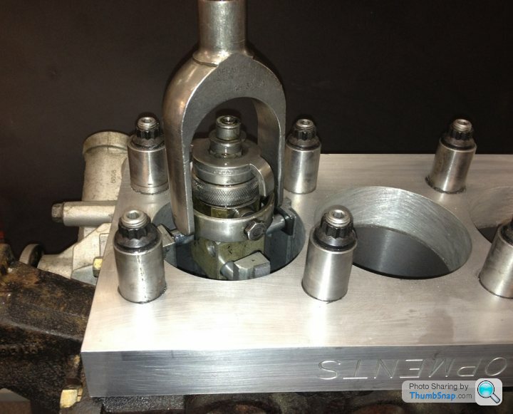
Here’s a picture of a bore being honed (again, not my engine). The torque plate is a thick metal plate, but not as thick as the actual cylinder head casting. So here extension tubes have been machined to allow the actual head studs to be used. The honing tool is four abrasive pads held against the cylinder walls by spring pressure:
Next time......... Con rods!! (Trust me; it’s genuinely interesting!!)
Porn!You’ll recall that the bores were badly scored by the ceramic “sand” that had worked its way back up the header pipes from the cats:
As standard, the bores of the cast alloy blocks are plated with Nikasil, a nickel/ceramic coating that provides a hard finish for the piston rings to run against. Boring and re-plating/honing would result in oversize bores, and oversize pistons aren’t available. So the options were a new block, or a sleeved one. The latter would be a £2k saving and would result in a harder-wearing finish. There were no obvious advantages to having a new block for me, so we decided to machine the old one.
The steel liners came from L.A. Sleeve of Santa Fe, Ca. and are flanged. That is to say that for most of their length, they are a thin-walled steel tube, but towards the top, cylinder head-end, they are much thicker-walled. Therefore they are much more positively seated than a sleeve without a flange. The bores are rebored to the outside diameter of the sleeve, and then counter-bored to the diameter and depth of the flange, before the deck is skimmed flat. With the head torqued down the flange is pressed firmly into its seat. This isn’t my block, nor L.A. Sleeve liners, but I’m sure mine looked very similar:
In the following pictures it appears that the bores have become Siamesed, and indeed they have, but only to the depth of the flange. Lower down, the alloy webs remain between the cylinders (and this IS my block):
Lower down in the bores, the liners have “windage” holes drilled through them, and this is a convenient time to show you one of the numerous differences between the 5.0 and 5.2 litre blocks. (Remember that the two V10 units (Lambo’s 5 and Audi’s 5.2) were developed separately from related, but different, 4 and 4.2 litre V8s.)
Here is an end shot of a (later) 5.2 litre block:
And my (earlier) 5.0 litre block
Note the two extra holes in the earlier block. These are the windage holes and pass through the lower end of each cylinder for the entire length of each bank. As the pistons thrash up and down, the air in the volumes below them is repeatedly being compressed and expanded. In the earlier engine, these pressure changes are alleviated and reduced by the air being allowed to pass from one bore to the next through the windage holes (in addition to it passing under the base of each bore). This extra alleviation of the pressure changes wasn’t needed in the later engines due to the increased efficiency of the oil scavenge pump fitted to the latter. Of much greater power (six chambers rather than three?) it can pump oil from the dry sump back to the oil tank at a much greater rate. Therefore the oil is less likely to become aerated in the short time that it spends under the thrashing pistons, and so there is less need to reduce the air pressure differences with the later oil pump.
Who knew? (Well, Ricky for one!)
Anyway, here is one of the windage holes in a cylinder sleeve, as seen down one of the bores of my block:
(I should add that all of the shots of my block were taken shortly after it arrived back from the machinist. Ricky had been measuring up for the crank shell sizes and then it was going into his parts cleaning tank for several hours. That should have shifted not only the swarf in the galleries, but the dead flies too!!)
With the sleeves machined into place, they then have to be honed to size and shape. And it was this process that led to the biggest delay in the machining process. Because, in all of the photos of my block above, the bore is the wrong shape!!
When you torque down the cylinder head onto the block, it distorts the block itself. (And indeed, how the block is distorted depends on whether the head is held down by studs or bolts, the former squashing the top of the block, the latter the bottom.) As you look at the photos above, the bores are not round! They will only become so again when the cylinder heads are torqued down onto them. Therefore, before the cylinder liners can be honed to size, the block has to be distorted in exactly the same way as if the heads were in place and torqued down.
This is achieved by the use of “Torque Plates”. These are THICK metal plates that are bolted down onto the block in exactly the same way as the cylinder heads are (either studs or bolts) and to the same torque, but with large holes in them allowing the honing tool to pass through them. The machinists “had” them, but couldn’t find them! Ricky has his own, but they were apparently too deep for the machine shop. So they had to make up a new set.......
Here’s a picture of a bore being honed (again, not my engine). The torque plate is a thick metal plate, but not as thick as the actual cylinder head casting. So here extension tubes have been machined to allow the actual head studs to be used. The honing tool is four abrasive pads held against the cylinder walls by spring pressure:
Next time......... Con rods!! (Trust me; it’s genuinely interesting!!)
Edited by 4321go on Sunday 11th August 21:44
Thanks chaps!
So firstly, how do you make a connecting rod?:
Cast/forge/sinter your rod. Machine the hole in the little end and press in your bushing. Drill your two holes in the big end for the con-rod bolts. Maybe tap these holes too. Now cut the big end in half. The hole for your crank pin will no longer be round, but this isn’t really very important at this stage. Take the rod and it’s end cap and machine their mating surfaces to accept a collet to ensure that when they are joined together, there is no possibility of the two pieces moving relative to one another. Now join them back together and torque-up the con rod bolts. Finally, machine the big-end hole to the correct, round size.
Here’s the finished big end of a connecting rod. It happens to be a CP Carrillo rod for a 5.2 litre, forced induction build of Ricky’s:

I had the choice of Carrillo rods to match the pistons (circa £2800 IIRC) or OEM Audi rods (£1100). The Carrillo rods are perfectly machined things of beauty and it was tempting to spend the extra. But my engine doesn’t need them. They’re a must to contain the extreme forces generated by forced induction; a supercharger or twin-turbo conversion. But the Audi rods are easily good enough for my (relatively) standard build. Besides, the Audi rods are considerably lighter. As are the CP Carrillo gudgeon pins to suit. For forced induction engines, they produce a machine-steel pin, with massively thick walls and a narrow hole down the centre. For a NA engine, we’re still using Carrillo gudgeon pins because we’re using Carrillo pistons, but they’re of a similar wall thickness as the OEM Audi pins. So we’re using the lightest piston/gudgeon pin/con-rod combination available. Good-oh!
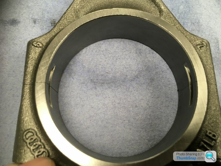
But onto those Audi connecting rods. What’s missing from this picture?
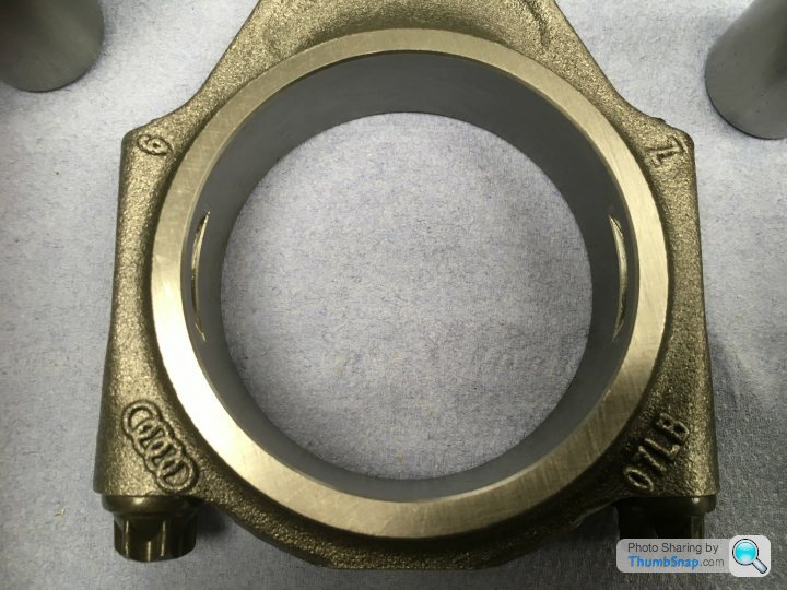
That’s right! There’s apparently no break in the big end!! How the hell do you install the bearing shells and clamp it around the crank pin?
And here’s where the economies of scale between an OE manufacturer and an aftermarket manufacturer show. CP Carrillo have to manufacture their rods in something like the fashion that I described above, although I probably missed out several hardening and machining steps. The Audi rods, in comparison, are “cracked”!
Their manufacturing process reads something like this:
Forge rod. Machine little end and press in bush. Drill and tap big end for the con-rod bolts and install said bolts. Machine hole for crank pin in big end. FREEZE the whole rod in liquid nitrogen. Hit with lump hammer.........
Yup, in that photo above, the big end is cracked in half at a crystalline level! And until you undo the con-rod bolts for the first time, you’ll never see the break. And when you’ve fitted the bearing shells and come to join the two halves back together again, they marry perfectly. Every time. And the mating faces can’t possible move relative to one another. So the big-end hole will be perfectly aligned. Every time!
I know! Genius, isn’t it!!!
Here are some shots of one of my rods that has been undone:
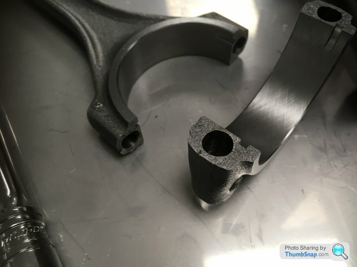
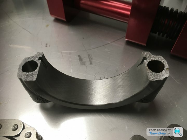
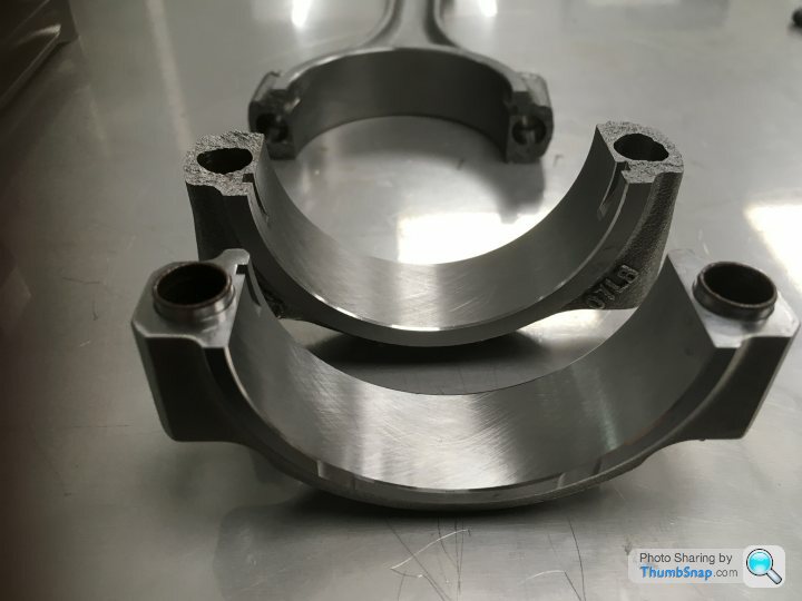
And here are the two end caps; CP Carrillo (with its machined-in collets) in the foreground, the unique crystalline face of the Audi “cracked rod” in the background:
And the rod married whole again. Torque-up the con-rod bolts (they haven’t been here) and that visible crack will be all-but invisible again:
Mind blowing!
So firstly, how do you make a connecting rod?:
Cast/forge/sinter your rod. Machine the hole in the little end and press in your bushing. Drill your two holes in the big end for the con-rod bolts. Maybe tap these holes too. Now cut the big end in half. The hole for your crank pin will no longer be round, but this isn’t really very important at this stage. Take the rod and it’s end cap and machine their mating surfaces to accept a collet to ensure that when they are joined together, there is no possibility of the two pieces moving relative to one another. Now join them back together and torque-up the con rod bolts. Finally, machine the big-end hole to the correct, round size.
Here’s the finished big end of a connecting rod. It happens to be a CP Carrillo rod for a 5.2 litre, forced induction build of Ricky’s:
I had the choice of Carrillo rods to match the pistons (circa £2800 IIRC) or OEM Audi rods (£1100). The Carrillo rods are perfectly machined things of beauty and it was tempting to spend the extra. But my engine doesn’t need them. They’re a must to contain the extreme forces generated by forced induction; a supercharger or twin-turbo conversion. But the Audi rods are easily good enough for my (relatively) standard build. Besides, the Audi rods are considerably lighter. As are the CP Carrillo gudgeon pins to suit. For forced induction engines, they produce a machine-steel pin, with massively thick walls and a narrow hole down the centre. For a NA engine, we’re still using Carrillo gudgeon pins because we’re using Carrillo pistons, but they’re of a similar wall thickness as the OEM Audi pins. So we’re using the lightest piston/gudgeon pin/con-rod combination available. Good-oh!
But onto those Audi connecting rods. What’s missing from this picture?
That’s right! There’s apparently no break in the big end!! How the hell do you install the bearing shells and clamp it around the crank pin?
And here’s where the economies of scale between an OE manufacturer and an aftermarket manufacturer show. CP Carrillo have to manufacture their rods in something like the fashion that I described above, although I probably missed out several hardening and machining steps. The Audi rods, in comparison, are “cracked”!
Their manufacturing process reads something like this:
Forge rod. Machine little end and press in bush. Drill and tap big end for the con-rod bolts and install said bolts. Machine hole for crank pin in big end. FREEZE the whole rod in liquid nitrogen. Hit with lump hammer.........
Yup, in that photo above, the big end is cracked in half at a crystalline level! And until you undo the con-rod bolts for the first time, you’ll never see the break. And when you’ve fitted the bearing shells and come to join the two halves back together again, they marry perfectly. Every time. And the mating faces can’t possible move relative to one another. So the big-end hole will be perfectly aligned. Every time!
I know! Genius, isn’t it!!!
Here are some shots of one of my rods that has been undone:
And here are the two end caps; CP Carrillo (with its machined-in collets) in the foreground, the unique crystalline face of the Audi “cracked rod” in the background:
And the rod married whole again. Torque-up the con-rod bolts (they haven’t been here) and that visible crack will be all-but invisible again:
Mind blowing!
That IS very interesting. I didn't know that was done for con rods. Seems to work on the same principle of this.
https://www.youtube.com/watch?v=KqVydQ6EdDg&fr...
https://www.youtube.com/watch?v=KqVydQ6EdDg&fr...
Here’s a picture of a bore being honed (again, not my engine). The torque plate is a thick metal plate, but not as thick as the actual cylinder head casting. So here extension tubes have been machined to allow the actual head studs to be used. The honing tool is four abrasive pads held against the cylinder walls by spring pressure:
Very interesting reading about this rebuild, however could I just make a point regarding the honing process and in particular to the pads being held by spring pressure.
They are held against the bore by pressure exerted from the head mechanism if they were held by spring pressure then they would follow what ever shape the hole is. This is why those cheap crappy hone tools sold on eBay etc are useless.
I used to work as an application engineer for Delapena Honing many years ago
4321go said:
Thanks chaps!
So firstly, how do you make a connecting rod?:
Cast/forge/sinter your rod. Machine the hole in the little end and press in your bushing. Drill your two holes in the big end for the con-rod bolts. Maybe tap these holes too. Now cut the big end in half. The hole for your crank pin will no longer be round, but this isn’t really very important at this stage. Take the rod and it’s end cap and machine their mating surfaces to accept a collet to ensure that when they are joined together, there is no possibility of the two pieces moving relative to one another. Now join them back together and torque-up the con rod bolts. Finally, machine the big-end hole to the correct, round size.
Here’s the finished big end of a connecting rod. It happens to be a CP Carrillo rod for a 5.2 litre, forced induction build of Ricky’s:
I had the choice of Carrillo rods to match the pistons (circa £2800 IIRC) or OEM Audi rods (£1100). The Carrillo rods are perfectly machined things of beauty and it was tempting to spend the extra. But my engine doesn’t need them. They’re a must to contain the extreme forces generated by forced induction; a supercharger or twin-turbo conversion. But the Audi rods are easily good enough for my (relatively) standard build. Besides, the Audi rods are considerably lighter. As are the CP Carrillo gudgeon pins to suit. For forced induction engines, they produce a machine-steel pin, with massively thick walls and a narrow hole down the centre. For a NA engine, we’re still using Carrillo gudgeon pins because we’re using Carrillo pistons, but they’re of a similar wall thickness as the OEM Audi pins. So we’re using the lightest piston/gudgeon pin/con-rod combination available. Good-oh!
But onto those Audi connecting rods. What’s missing from this picture?
That’s right! There’s apparently no break in the big end!! How the hell do you install the bearing shells and clamp it around the crank pin?
And here’s where the economies of scale between an OE manufacturer and an aftermarket manufacturer show. CP Carrillo have to manufacture their rods in something like the fashion that I described above, although I probably missed out several hardening and machining steps. The Audi rods, in comparison, are “cracked”!
Their manufacturing process reads something like this:
Forge rod. Machine little end and press in bush. Drill and tap big end for the con-rod bolts and install said bolts. Machine hole for crank pin in big end. FREEZE the whole rod in liquid nitrogen. Hit with lump hammer.........
Yup, in that photo above, the big end is cracked in half at a crystalline level! And until you undo the con-rod bolts for the first time, you’ll never see the break. And when you’ve fitted the bearing shells and come to join the two halves back together again, they marry perfectly. Every time. And the mating faces can’t possible move relative to one another. So the big-end hole will be perfectly aligned. Every time!
I know! Genius, isn’t it!!!
Here are some shots of one of my rods that has been undone:
And here are the two end caps; CP Carrillo (with its machined-in collets) in the foreground, the unique crystalline face of the Audi “cracked rod” in the background:
And the rod married whole again. Torque-up the con-rod bolts (they haven’t been here) and that visible crack will be all-but invisible again:
Mind blowing!
Known as fracture split rods. There are now a few engines out there with fracture split main bearing caps as well.So firstly, how do you make a connecting rod?:
Cast/forge/sinter your rod. Machine the hole in the little end and press in your bushing. Drill your two holes in the big end for the con-rod bolts. Maybe tap these holes too. Now cut the big end in half. The hole for your crank pin will no longer be round, but this isn’t really very important at this stage. Take the rod and it’s end cap and machine their mating surfaces to accept a collet to ensure that when they are joined together, there is no possibility of the two pieces moving relative to one another. Now join them back together and torque-up the con rod bolts. Finally, machine the big-end hole to the correct, round size.
Here’s the finished big end of a connecting rod. It happens to be a CP Carrillo rod for a 5.2 litre, forced induction build of Ricky’s:
I had the choice of Carrillo rods to match the pistons (circa £2800 IIRC) or OEM Audi rods (£1100). The Carrillo rods are perfectly machined things of beauty and it was tempting to spend the extra. But my engine doesn’t need them. They’re a must to contain the extreme forces generated by forced induction; a supercharger or twin-turbo conversion. But the Audi rods are easily good enough for my (relatively) standard build. Besides, the Audi rods are considerably lighter. As are the CP Carrillo gudgeon pins to suit. For forced induction engines, they produce a machine-steel pin, with massively thick walls and a narrow hole down the centre. For a NA engine, we’re still using Carrillo gudgeon pins because we’re using Carrillo pistons, but they’re of a similar wall thickness as the OEM Audi pins. So we’re using the lightest piston/gudgeon pin/con-rod combination available. Good-oh!
But onto those Audi connecting rods. What’s missing from this picture?
That’s right! There’s apparently no break in the big end!! How the hell do you install the bearing shells and clamp it around the crank pin?
And here’s where the economies of scale between an OE manufacturer and an aftermarket manufacturer show. CP Carrillo have to manufacture their rods in something like the fashion that I described above, although I probably missed out several hardening and machining steps. The Audi rods, in comparison, are “cracked”!
Their manufacturing process reads something like this:
Forge rod. Machine little end and press in bush. Drill and tap big end for the con-rod bolts and install said bolts. Machine hole for crank pin in big end. FREEZE the whole rod in liquid nitrogen. Hit with lump hammer.........
Yup, in that photo above, the big end is cracked in half at a crystalline level! And until you undo the con-rod bolts for the first time, you’ll never see the break. And when you’ve fitted the bearing shells and come to join the two halves back together again, they marry perfectly. Every time. And the mating faces can’t possible move relative to one another. So the big-end hole will be perfectly aligned. Every time!
I know! Genius, isn’t it!!!
Here are some shots of one of my rods that has been undone:
And here are the two end caps; CP Carrillo (with its machined-in collets) in the foreground, the unique crystalline face of the Audi “cracked rod” in the background:
And the rod married whole again. Torque-up the con-rod bolts (they haven’t been here) and that visible crack will be all-but invisible again:
Mind blowing!
wilksy61 said:
however could I just make a point regarding the honing process
I’m an airline pilot. Whilst I can attack an old-tech British Classic with a spanner, there’s absolutely NO guarantee that it won’t result in a stripped thread!!I positively welcome being corrected and would encourage contributions from the experts as we go along.....
 k, I've broken the bloody thing!
4321go said:
I’m an airline pilot. Whilst I can attack an old-tech British Classic with a spanner, there’s absolutely NO guarantee that it won’t result in a stripped thread!!
I positively welcome being corrected and would encourage contributions from the experts as we go along.....
Cheers, you should see how they hone con rods due to the of area for a stone to correctly work on, and also can attack British Classics with a spanner and, depending how long they have been left outside, will almost certainly result in many stripped threadsI positively welcome being corrected and would encourage contributions from the experts as we go along.....
Great, long read, I'm laying on my back, with 7 purringo siamese kittens and reading it through, enjoying last warmt of sun (through window, mind you, +2°C outside) and getting ready to put my Vespa into winter hibernation. Thank you 4321go for sharing your experiences and troubles. These kind of topics are reason what makes Internet a great place.
Are you going to replace the clutch or exhaust manifolds while you are at it?
I've been lurking in W11 forum for quite along time and I have a hunch that I have found connection with "splat"
Cheers
Samuli
Are you going to replace the clutch or exhaust manifolds while you are at it?
I've been lurking in W11 forum for quite along time and I have a hunch that I have found connection with "splat"
Cheers
Samuli
Edited by SamuliS on Saturday 5th October 11:12
Ha! Yup, that’s me. Well sleuthed!
The clutch and release bearing were replaced about 5000 miles ago. I avoid full-bore standing starts, short-shift around second and double declutch all of my gear changes. So the last clutch lasted over 60,000 miles! As for the exhaust system, I failed to buy a pair of beautiful looking, German manufactured, stainless steel tubular headers on fleabay a few years ago (cheap at £2000 IIRC) so the originals will go back on. With decat pipes and an original OEM Superleggera system (a super-lucky eBay gamble, hardly used and £155!!), it’s pretty free-flowing and sounds incredible.
And talking of sound........
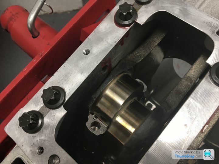
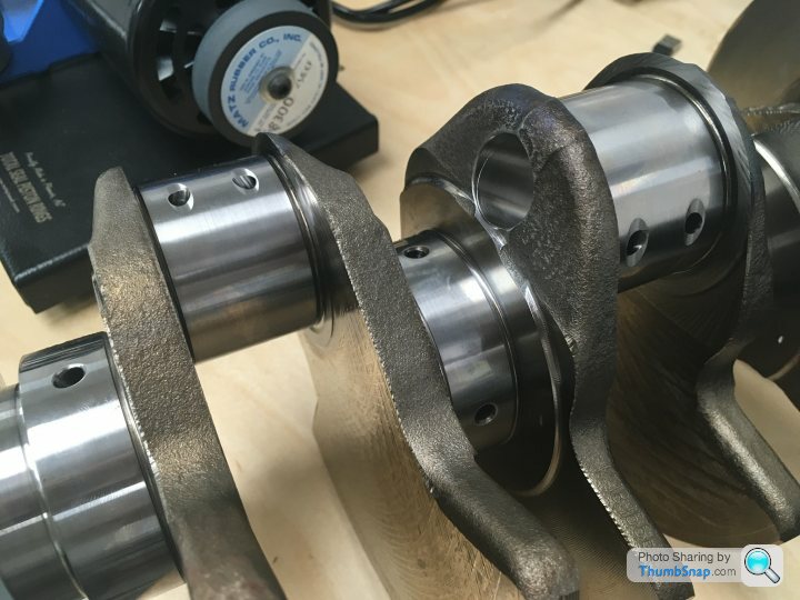
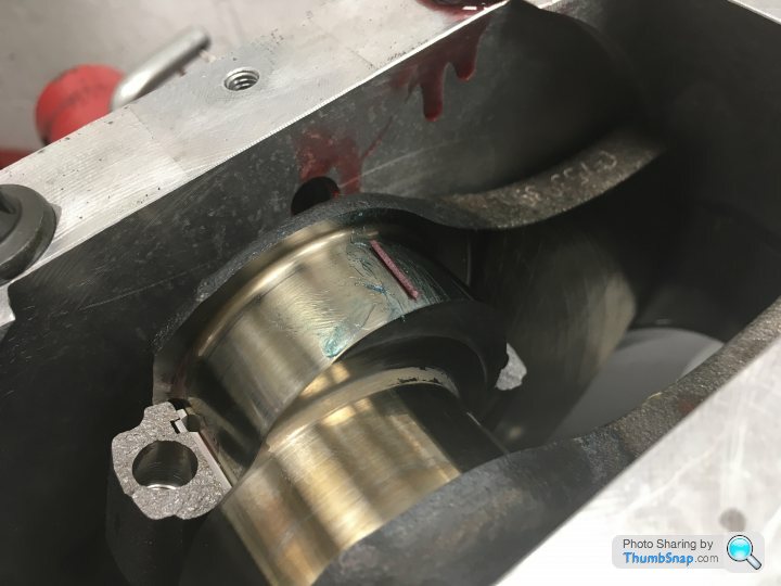
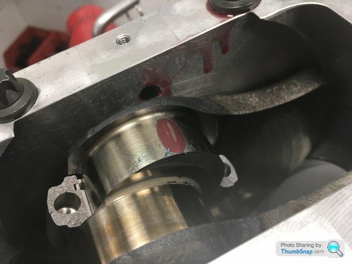
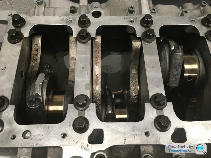
It’s often noted that the 5.0 litre Gallardo engine is one of the best sounding out there. It’s generally agreed that it’s much better sounding than the replacement 5.2 litre LP-series engines. And that’s down to the crank. On any V engine, two con rods sit together on a journal between a pair of crank webs. On the later engine, that journal is a straight one; the pairs of con rods sit side-by-side. But on the earlier engines, the journals are staggered. Which subtly alters the firing angle and hence the sound of the engine. As ever, much easier to illustrate with photos:
My crank, with the staggered journals between the webs (and note crystalline face of one of those fractured rods going into place):
And a later 5.2 engine, with straight journals:
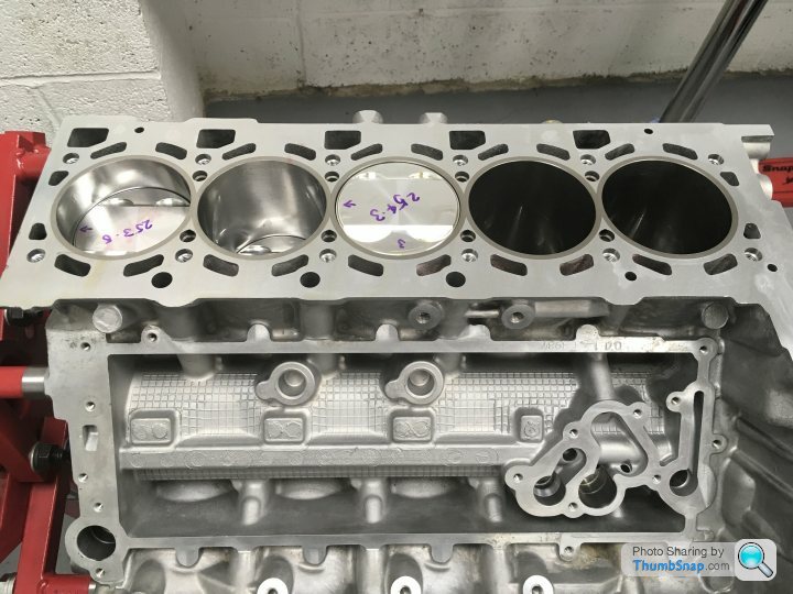
The first photo suggests that my engine is finally coming together again. And it is!
All of the rings have been individually gapped:
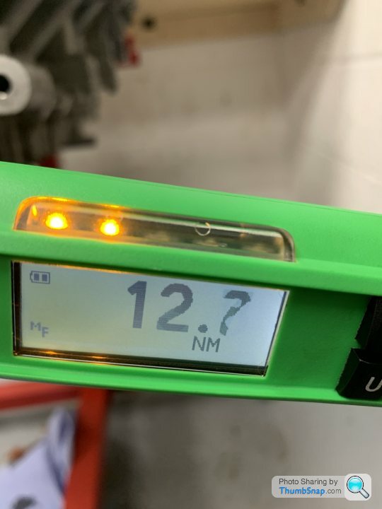
And as each component is assembled, Ricky initially does so without any build lube, instead using plastigauge to check that the tolerances that he’s previously calculated by exacting measurements are indeed as expected:
A time-consuming process, and not a level of detail that is bothered with when the engines are originally slapped together on the line, but the results speak for themselves. With the crank and all ten pistons installed, the breakaway torque, the force needed to spin the crank (clamped tightly within the block), all ten con rods (clamped around the crank) and run thirty piston rings up and down the cross-honed bores, is less than 13 Nm. For the non-mechanically minded, that’s an impressively small number!
The clutch and release bearing were replaced about 5000 miles ago. I avoid full-bore standing starts, short-shift around second and double declutch all of my gear changes. So the last clutch lasted over 60,000 miles! As for the exhaust system, I failed to buy a pair of beautiful looking, German manufactured, stainless steel tubular headers on fleabay a few years ago (cheap at £2000 IIRC) so the originals will go back on. With decat pipes and an original OEM Superleggera system (a super-lucky eBay gamble, hardly used and £155!!), it’s pretty free-flowing and sounds incredible.
And talking of sound........
It’s often noted that the 5.0 litre Gallardo engine is one of the best sounding out there. It’s generally agreed that it’s much better sounding than the replacement 5.2 litre LP-series engines. And that’s down to the crank. On any V engine, two con rods sit together on a journal between a pair of crank webs. On the later engine, that journal is a straight one; the pairs of con rods sit side-by-side. But on the earlier engines, the journals are staggered. Which subtly alters the firing angle and hence the sound of the engine. As ever, much easier to illustrate with photos:
My crank, with the staggered journals between the webs (and note crystalline face of one of those fractured rods going into place):
And a later 5.2 engine, with straight journals:
The first photo suggests that my engine is finally coming together again. And it is!
All of the rings have been individually gapped:
And as each component is assembled, Ricky initially does so without any build lube, instead using plastigauge to check that the tolerances that he’s previously calculated by exacting measurements are indeed as expected:
A time-consuming process, and not a level of detail that is bothered with when the engines are originally slapped together on the line, but the results speak for themselves. With the crank and all ten pistons installed, the breakaway torque, the force needed to spin the crank (clamped tightly within the block), all ten con rods (clamped around the crank) and run thirty piston rings up and down the cross-honed bores, is less than 13 Nm. For the non-mechanically minded, that’s an impressively small number!
Gassing Station | Supercar General | Top of Page | What's New | My Stuff