3/5/7 angle valve jobs?
Discussion


Haven't read the whole thread as it's getting late, but I saw those lovely looking guide bosses on Dart heads and thought I'd post a pic of what they look like 'as cast'...

These are Dart Pro-1 215s which are currently on my 383 and made just a hair shy of 500bhp on the Knight Racing Services dyno.
PS. The only work I had the balls to do was to bowl blend and get rid of that nasty ridge between the valve seat and the valve throat.
These are Dart Pro-1 215s which are currently on my 383 and made just a hair shy of 500bhp on the Knight Racing Services dyno.
PS. The only work I had the balls to do was to bowl blend and get rid of that nasty ridge between the valve seat and the valve throat.
Blimey, mine came with a little bit of hand finishing from the factory, but i did alot more to them when i went up on bore size.
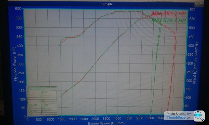
I tidied up the fuelling in the mid range a couple of weeks back, i did a couple of power runs, and was 581 bhp and 594 lbs ft.
Short shifting at 4k still means 450bhp and nearly 600lbs
I tidied up the fuelling in the mid range a couple of weeks back, i did a couple of power runs, and was 581 bhp and 594 lbs ft.
Short shifting at 4k still means 450bhp and nearly 600lbs
ian_uk1975 said:
Yea, I bought mine as bare castings, so perhaps assembled heads from Dart also come with some hand finishing?
Impressive numbers, esp. in the chassis with full exhaust. What's the motor spec?
416CI LS3 block, forges internals, throttle bodies, big cam, Dart heads ported and matched, comp valve springs, Ti retainers.Impressive numbers, esp. in the chassis with full exhaust. What's the motor spec?

varnish5000 said:
That’s interesting.
The way I have thought about developing a head is consider how much air the engine wants, which is basically a function of engine displacement and rpm.
Then see what valve size is needed to get that much air into the engine, by just applying a discharge coefficient and taking into consideration the valve stem diameter and seat width.
What he said^^^^^^^ did no one answer him I would be interested to know this as well is there not something such as the optimum inlet valve size or area for a cylinder displacement? The way I have thought about developing a head is consider how much air the engine wants, which is basically a function of engine displacement and rpm.
Then see what valve size is needed to get that much air into the engine, by just applying a discharge coefficient and taking into consideration the valve stem diameter and seat width.
From what Iv read people fit bigger inlets and port to suit but it might not be needed if I valve Dia is at the correct size for the cylinder displacement.
How bad is reversion is it something that worsens with long duration cams?
I see some experts put a step below the inlet valve seats so that air flows over the step past the valve and I to the cylinder but on the way back out it will hit the step.
The inlet ports on the cylinder head will be ported bigger at the entry where it mates to the inlet manifold for the same reason.
Iv also seen it mentioned that the the exhaust manifold primaries are larger than the exhaust ports on the cylinder head so that gases returning back hit the mismatch on the cylinder head.
Would be good to hear from the experts on this.
Just wondering if anti reversion measures messes with pulse tuning?
Edited by delcbr on Friday 14th February 20:45
Hi All,
Found this thread whilst searching for information on cylinder head porting and valve seat angles.
I realize that this is an old thread.
Don't want to be a "Grave Robber" persay,but the information within is very interesting.Especially the observations made by Pumaracing.
Have been studying and experimenting on porting techniques and valve angles for quite a while now.Main emphasis being cast iron SB chevy heads,cause thats what I have laying around.
I just wanted to touch on a few statements,for my own clairity, if nobody minds.If not then boot me off and I'll go back to the garage.
The first statement from Pumaracing that caught me was,
"So why does everyone use cutters with 60 degree bottom angles? Because that's what the seat machine manufacturers list as stock items and hardly anyone out there is smart enough to question it. Actually OE heads usually have the correct 70 degree or similar bottom cut angle which your local engine reconditioner will happily and cluelessly bugger up when he refurbishes the head for you."
This statement echoed through my head as I was looking at tooling for installing valveguide liners.
I'm sure most are familiar with this product.
http://www.goodson.com/CL-343-Bronze-Liner_Master_...
Thing is,this setup uses centering cones.
http://www.goodson.com/Seat-Centering-Cones/
Now my question:
If I have a set of virgin heads(meaning never had any work done)that need guide work.How is a
60° centering cone of any use , when the stock bottom cut is 70° or similar?Am I right in assuming that I first have to cut a 60 and then I can center up with the cones?Doing this makes me think I'm well on my way to installing bigger valves.
Which leads me to my next delima.
According to everything I've read when it come to a simple 3 angle(30°/45°/60°)valve job, the 60° is cut first,then the 30°,and the ridge in the middle is the landing for the 45° seat cut.Incidentally,this is the very same procedure used in enlarging the seats for bigger valves.
I've tried this on some old, cracked, 1.94 heads and it works perfectly.....if your putting bigger valves in.I also tried just cleaning up the 45,and then doing the bottom and top cuts.I always end up with a thin 45 seat.
Am I correct in assuming that if you wish to retain a particular valve diameter while cutting the 30/45/60 angles,you will end up with a 45° seat width thats either way to thin,or top and bottom cuts that are only half the seat width or less?If so is there any point to a 3 Angle with original valve diameters?
Pumaracing said:
Having spent 20 years studying the effect of cylinder head modifications on my flowbench all I can tell you is it's far too complicated to summarise into simple rules like "more cut angles = better".
A completely smooth radiused seat will not necessarily flow more (usually less) than one with discrete seat angles and sharp edges between them. Sharks have rough skin (in fact most fish have scales) because the discontinuities actually reduce surface friction and drag. Golf balls have dimples because that lets them fly further than a ball with a smooth surface. "Smooth" does not always equate to friction free or higher flow.
The choice of seat width and bottom cut angle are far more important than just the number of cut angles which tell you bugger all about the knowledge of the person doing the job. Most places just have a small range of standard cutters which can't possibly be right for every valve size and nearly everyone cuts the main seat too narrow. A nice wide seat conducts heat away much better. The OE seat width is usually spot on because the person who designed the engine knew a lot more than the idiot with the Serdi who thinks 1mm wide valve seats are "race seats" or somehow better than what was there to start with.
Seat concentricity is more important than just about everything else combined and the commonly used Serdi machines are awful at achieving that unless the guides are in perfect condition. In fact most places with Serdis will try and tell you they need to either replace the guides first or at least hone them out (which of course buggers them) until they fit their next larger seat cutting pilot just to get the machine to work properly (they won't actually admit it's to get the crappy machine design to work properly of course). Far better are machines with fixed pilots which lock into the guides like the Sunnen system than rotating pilots like the Serdi where any play between guide and pilot translates straight into seats with poor concentricity.
Seats that flow well at high valve lift don't always flow well at low valve lift and vice versa. Seats that flow the absolute most might not last very long. Everything is a compromise and every seat I've ever cut has been tailored to the exact engine spec, cam lift, its intended use and the valve sizes.
If you want some simple rules for general use the 45 degree seat should be about 4.5% of the inlet valve diameter wide and use the same width on the exhaust seats which will usually translate to about 5.5% of their diameter seeing as they are smaller. So a 50mm inlet valve will want a 2.25mm wide seat and so on.
A 70 degree bottom cut always outflows the normally used 60 degree cut because it better splits the transition from 90 degree throat to 45 degree seat. A 60 degree bottom cut means a 30 degree transition from the throat and only 15 degrees from the seat angle which is a stupid way of trying to minimise the change of flow direction. Obviously the ideal would be to split the 45 degree difference and use a 67.5 degree bottom cut.
So why does everyone use cutters with 60 degree bottom angles? Because that's what the seat machine manufacturers list as stock items and hardly anyone out there is smart enough to question it. Actually OE heads usually have the correct 70 degree or similar bottom cut angle which your local engine reconditioner will happily and cluelessly bugger up when he refurbishes the head for you.
Similarly the top cut should split the difference between seat angle and chamber roof angle, i.e. with a flat chamber roof use a 22.5 degree top cut. With hemi heads or other heads with angled roofs use a bigger angle like 30 or 35 degrees.
So phone up a few people and ask them some searching questions because you now already know more than they do. Ask them what seat width they suggest and why. When they say they use 1.5mm on everything because that's the cutter they bought with the machine or that wide seats are good for road heads and narrow seats are good for race heads you can put the phone down. Ask them what bottom cut angle they use and why. When they say they've never given it much thought or they use 60 degrees because that's how the cutters are made you can put the phone down. Same for top cut angle.
Ask them how much time they've spent testing different seat widths and angles for flow on a flowbench. When they say "what's a flowbench?" you can put the phone down.
Ask them what concentricity level they strive for. They'll probably say their seat machine has a vacuum tester built in and they test every seat for leakage - at which point you can put the phone down. The trouble is a 45 degree valve and a 47 degree (or any other angle) seat will still touch at one point all the way round so it'll seal against vacuum but be worse than useless and burn straight out in service. I've watched a Serdi machine test every seat as perfect for leakage but then none of them would actually lap in and it all had to be redone. Only the fact that I was standing there glowering at people meant it got redone properly! I glower very well when the occasion requires it.
You have about as much chance of getting a set of valve seats cut perfectly (well what in my view is perfect) as of winning the lottery. In fact it is a lottery. If you can find someone who can answer all the above questions without you having to put the phone down first please let us know.
Do you do valve jobs if so where are you loacted not sure if youll get this seens post was from 2011A completely smooth radiused seat will not necessarily flow more (usually less) than one with discrete seat angles and sharp edges between them. Sharks have rough skin (in fact most fish have scales) because the discontinuities actually reduce surface friction and drag. Golf balls have dimples because that lets them fly further than a ball with a smooth surface. "Smooth" does not always equate to friction free or higher flow.
The choice of seat width and bottom cut angle are far more important than just the number of cut angles which tell you bugger all about the knowledge of the person doing the job. Most places just have a small range of standard cutters which can't possibly be right for every valve size and nearly everyone cuts the main seat too narrow. A nice wide seat conducts heat away much better. The OE seat width is usually spot on because the person who designed the engine knew a lot more than the idiot with the Serdi who thinks 1mm wide valve seats are "race seats" or somehow better than what was there to start with.
Seat concentricity is more important than just about everything else combined and the commonly used Serdi machines are awful at achieving that unless the guides are in perfect condition. In fact most places with Serdis will try and tell you they need to either replace the guides first or at least hone them out (which of course buggers them) until they fit their next larger seat cutting pilot just to get the machine to work properly (they won't actually admit it's to get the crappy machine design to work properly of course). Far better are machines with fixed pilots which lock into the guides like the Sunnen system than rotating pilots like the Serdi where any play between guide and pilot translates straight into seats with poor concentricity.
Seats that flow well at high valve lift don't always flow well at low valve lift and vice versa. Seats that flow the absolute most might not last very long. Everything is a compromise and every seat I've ever cut has been tailored to the exact engine spec, cam lift, its intended use and the valve sizes.
If you want some simple rules for general use the 45 degree seat should be about 4.5% of the inlet valve diameter wide and use the same width on the exhaust seats which will usually translate to about 5.5% of their diameter seeing as they are smaller. So a 50mm inlet valve will want a 2.25mm wide seat and so on.
A 70 degree bottom cut always outflows the normally used 60 degree cut because it better splits the transition from 90 degree throat to 45 degree seat. A 60 degree bottom cut means a 30 degree transition from the throat and only 15 degrees from the seat angle which is a stupid way of trying to minimise the change of flow direction. Obviously the ideal would be to split the 45 degree difference and use a 67.5 degree bottom cut.
So why does everyone use cutters with 60 degree bottom angles? Because that's what the seat machine manufacturers list as stock items and hardly anyone out there is smart enough to question it. Actually OE heads usually have the correct 70 degree or similar bottom cut angle which your local engine reconditioner will happily and cluelessly bugger up when he refurbishes the head for you.
Similarly the top cut should split the difference between seat angle and chamber roof angle, i.e. with a flat chamber roof use a 22.5 degree top cut. With hemi heads or other heads with angled roofs use a bigger angle like 30 or 35 degrees.
So phone up a few people and ask them some searching questions because you now already know more than they do. Ask them what seat width they suggest and why. When they say they use 1.5mm on everything because that's the cutter they bought with the machine or that wide seats are good for road heads and narrow seats are good for race heads you can put the phone down. Ask them what bottom cut angle they use and why. When they say they've never given it much thought or they use 60 degrees because that's how the cutters are made you can put the phone down. Same for top cut angle.
Ask them how much time they've spent testing different seat widths and angles for flow on a flowbench. When they say "what's a flowbench?" you can put the phone down.
Ask them what concentricity level they strive for. They'll probably say their seat machine has a vacuum tester built in and they test every seat for leakage - at which point you can put the phone down. The trouble is a 45 degree valve and a 47 degree (or any other angle) seat will still touch at one point all the way round so it'll seal against vacuum but be worse than useless and burn straight out in service. I've watched a Serdi machine test every seat as perfect for leakage but then none of them would actually lap in and it all had to be redone. Only the fact that I was standing there glowering at people meant it got redone properly! I glower very well when the occasion requires it.
You have about as much chance of getting a set of valve seats cut perfectly (well what in my view is perfect) as of winning the lottery. In fact it is a lottery. If you can find someone who can answer all the above questions without you having to put the phone down first please let us know.
stevieturbo said:
GreenV8S said:
I think it's unlikely that Dave will see your post here, but perhaps a web search for Dave Baker Pumaracing would turn up contact details for him elsewhere.
And he's retired anyway.Pumaracing said:
If anyone can actually derive from first principles the equations that determine valve gap and flow area versus valve lift then even more kudos but perhaps that's getting a bit too technical for a forum like this. However it's pretty straightforward if you have say decent A level maths or entry level university maths, understand the cosine rule and general aspects of trigonometry. Hopefully someone can have a crack at it.
Holy thread resurrection , Batman.I was pointed to this thread from my flow bench thread and saw the quoted post.
I've done this in Excel, if PumaRacing (or anybody else) is still interested.
Also posted in https://www.pistonheads.com/gassing/topic.asp?h=0&... - please reply in the other thread if your answer is not appropriate to this thread.
Hopefully, one of the earlier posters will read this...
According to Helgesen, the orifice sizes for the following volumetric air flows are...
5CFM --> 0.210"
10CFM --> 0.296"
20CFM --> 0.419"
40CFM --> 0.594"
80CFM --> 0.840"
160CFM --> 1.185"
From the equation, Diameter = SQRT ( ( 4 * Q ) / ( SQRT ( 2 * ( Change in Pressure ) / Density ) ) ) we get...
5CFM --> 0.209"
10CFM --> 0.295"
20CFM --> 0.418"
40CFM --> 0.591"
80CFM --> 0.836"
160CFM --> 1.182"
Can anybody explain why some of the calculated orifice diameters are outside the tolerance values of the Helgesen diameters?
Is it a case of "close is good enough" and just ignore the +/-0.001" tolerance?
Edited by pingu393 on Monday 3rd September 23:44
Not quite sure what you mean, are you saying valve head diameter vs seat insert OD?
If yes then we measure gap between inlet ex valves on 2 valve head or gaps twixt inlet/inlet/ex/ex/inlet etc etc on multi valve head/ we then fit the largest OD inserts we can whilst leaving at least half a mm gap between adjacent inserts. We feel this gives us best chance of inserts staying put in use. It also lead us, with larger than 44mm OD valves to develop larger width seats and extra seat angle widths to keep seat insert ID as small as we can without losing bulk flow. it biases the flow to lower valve openings but maintains same overall flow through valve.
If yes then we measure gap between inlet ex valves on 2 valve head or gaps twixt inlet/inlet/ex/ex/inlet etc etc on multi valve head/ we then fit the largest OD inserts we can whilst leaving at least half a mm gap between adjacent inserts. We feel this gives us best chance of inserts staying put in use. It also lead us, with larger than 44mm OD valves to develop larger width seats and extra seat angle widths to keep seat insert ID as small as we can without losing bulk flow. it biases the flow to lower valve openings but maintains same overall flow through valve.
PeterBurgess said:
Not quite sure what you mean, are you saying valve head diameter vs seat insert OD?
If yes then we measure gap between inlet ex valves on 2 valve head or gaps twixt inlet/inlet/ex/ex/inlet etc etc on multi valve head/ we then fit the largest OD inserts we can whilst leaving at least half a mm gap between adjacent inserts. We feel this gives us best chance of inserts staying put in use. It also lead us, with larger than 44mm OD valves to develop larger width seats and extra seat angle widths to keep seat insert ID as small as we can without losing bulk flow. it biases the flow to lower valve openings but maintains same overall flow through valve.
no, i mean the followingIf yes then we measure gap between inlet ex valves on 2 valve head or gaps twixt inlet/inlet/ex/ex/inlet etc etc on multi valve head/ we then fit the largest OD inserts we can whilst leaving at least half a mm gap between adjacent inserts. We feel this gives us best chance of inserts staying put in use. It also lead us, with larger than 44mm OD valves to develop larger width seats and extra seat angle widths to keep seat insert ID as small as we can without losing bulk flow. it biases the flow to lower valve openings but maintains same overall flow through valve.
- width of the 45 on the valve vs the width of the 45 on the head insert. what are people referring to when they state the size ?
- also the valve OD vs the seat OD (the edge of the 45 cut not the overall insert OD)
stevesingo said:
For referance, here is the workshop repair manual for the BMW s14 engine valves and seats...
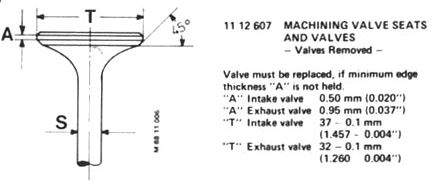
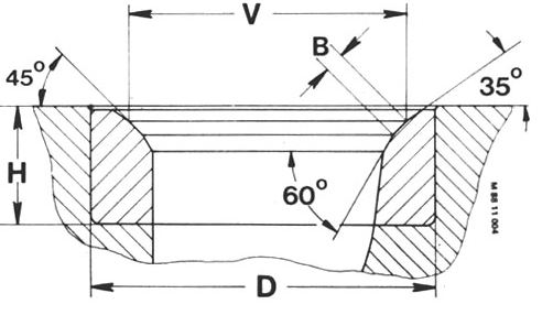
V= In 36.6mm Ex 31.4mm +0.1mm tolerance
B= In 1.2mm Ex 1.4mm +0.1mm tolerance
Interesting that the valves are bigger than the seats..
Steve
some of the issues i am mentioning are briefly raised hereV= In 36.6mm Ex 31.4mm +0.1mm tolerance
B= In 1.2mm Ex 1.4mm +0.1mm tolerance
Interesting that the valves are bigger than the seats..
Steve
i.e. T is bigger than V by a smidge. but what is the 45 width on the valve ?
I am with you now.
With regard to head diameter (therefore valve seat OD) being a little wider than the seat diameter in the head I assume it allows for heat expansion. However, on inlet valves, especially when going over 43 mm, it can aid flow at low to medium valve lifts having the seat diameter a mm or so less than the valve OD. With smaller valves the ensuing narrower diameter valve throat restricts flow too much for this to work. I would like to be able to say this is my amazing intellect and understanding of airflow but I would be lying; I put a 43 mm valve on a 41 mm seat for flow testing by mistake and saw some interesting effects
I do not think there is a hard and fast rule for actual seat width compared to the seat width in the head. It comes down to flow characteristics and preference for work done. For instance we use 1 mm head seat widths in valves below 35 mm. Obviously a 1 mm seat on a valve underhead would give an odd shape to work on to get a good flowing valve. Most seat widths on proprietary valves when modded probably fall in the 1.5 to 2.5 mm range. On BIG Harley valves and V8 valves we are often running 4mm valve seat widths on 2-3 mm seat in the head widths.
PeterBurgess said:
I am with you now.
With regard to head diameter (therefore valve seat OD) being a little wider than the seat diameter in the head I assume it allows for heat expansion. However, on inlet valves, especially when going over 43 mm, it can aid flow at low to medium valve lifts having the seat diameter a mm or so less than the valve OD. With smaller valves the ensuing narrower diameter valve throat restricts flow too much for this to work. I would like to be able to say this is my amazing intellect and understanding of airflow but I would be lying; I put a 43 mm valve on a 41 mm seat for flow testing by mistake and saw some interesting effects
I do not think there is a hard and fast rule for actual seat width compared to the seat width in the head. It comes down to flow characteristics and preference for work done. For instance we use 1 mm head seat widths in valves below 35 mm. Obviously a 1 mm seat on a valve underhead would give an odd shape to work on to get a good flowing valve. Most seat widths on proprietary valves when modded probably fall in the 1.5 to 2.5 mm range. On BIG Harley valves and V8 valves we are often running 4mm valve seat widths on 2-3 mm seat in the head widths.
Out of interest, did you measure the flow rate with the valve static at different valve lifts, or have you constructed single cylinder rig that will measure flow through a moving valve with the appropriate amount of accelerating air?With regard to head diameter (therefore valve seat OD) being a little wider than the seat diameter in the head I assume it allows for heat expansion. However, on inlet valves, especially when going over 43 mm, it can aid flow at low to medium valve lifts having the seat diameter a mm or so less than the valve OD. With smaller valves the ensuing narrower diameter valve throat restricts flow too much for this to work. I would like to be able to say this is my amazing intellect and understanding of airflow but I would be lying; I put a 43 mm valve on a 41 mm seat for flow testing by mistake and saw some interesting effects
I do not think there is a hard and fast rule for actual seat width compared to the seat width in the head. It comes down to flow characteristics and preference for work done. For instance we use 1 mm head seat widths in valves below 35 mm. Obviously a 1 mm seat on a valve underhead would give an odd shape to work on to get a good flowing valve. Most seat widths on proprietary valves when modded probably fall in the 1.5 to 2.5 mm range. On BIG Harley valves and V8 valves we are often running 4mm valve seat widths on 2-3 mm seat in the head widths.
Or, has it been shown that static valve testing with constant flow is an accurate representation of a moving piston and a moving valve?
Gassing Station | Engines & Drivetrain | Top of Page | What's New | My Stuff