Ideal Camshaft Lobe Centreline Angle
Discussion


Time for a heated debate as Mrs Merton used to say, if anyone remembers that programme.
There's been some discussion on the above topic recently. Most of what you see about it in print has been written by Mr Vizard and his own views on the matter can be read here.
http://www.stockcarracing.com/techarticles/scrp_06...
In essence he believes that the primary determinant of the ideal LCA for a performance cam is the cylinder size divided by the inlet valve diameter (CID/inch) and as that number gets bigger the LCA should decrease and vice versa. It culminates in this graph.

The equation of the line can be calculated as LCA = 132 - (16/14 x CID/inch)
So here's where we get into the heated debate. I submit that the cylinder size / valve size ratio has absolutely nothing to do with LCA, or at least very little and that the graph above is not a determinant of the ideal LCA. Fighting talk eh? Well I'll expound.
Firstly I should say that's it up to DV himself to say whether he claims that graph can be applied to engines other than the Chevy but it would be weird if only that specific engine had some sort of relationship that could be charted that no other engine followed. Anyway I'll assume it is indeed meant to be a universal panacea.
So how does it stack up in practice? There's a well known scientific method of finding out whether a relationship holds true which is to extrapolate that relationship to its extremes. I can't think of any common engine that has a bigger CID/inch than the maximum of 28 shown on the chart but there are lots that have a smaller number than 14, the minimum shown.
Let's start with the humble A series. A 1275cc MG Metro with 35.6mm inlets has a ratio of 14, right at the bottom of the range of values shown. According to the graph it should want an LCA of 116 degrees. Does it? Well there's a very good authority on the matter in the form of a book written by a certain Mr Vizard which states that nearly every Mini engine he ever tested required an LCA in the range 100 to 106 degrees for a performance cam. However the A series is a bit weird in terms of its siamese ports so lets stick with more conventional one port per cylinder engines.
The Peugeot TU 1360 8v engine has 39.3mm inlet valves. That gives it a ratio of 13.4 CID/inch which indicates an LCA of 116.7 degrees. Is that what it really wants? Not on your nelly. 106 to 108 degrees is more like it from the ones I've built as in fact we'll soon see the range 100 to 110 degrees applies to nearly every other engine.
Let's extrapolate further to 16v engines which have even smaller ratios of CID per inch of valve diameter.
The well known Vauxhall XE 16v has 500cc cylinders and 33mm inlet valves. A ratio of 11.7 CID/inch and an LCA of 118.6 degrees from the above equation. A friend dynoed a tuned one some time ago and spent a fair amount of effort on cam swings. He settled on 105 degrees inlet full lift and though I can't recall the exhaust figure it was somewhat similar and the LCA must also have been in that ballpark.
Let's go even further to motorbike engines. The 2005 Honda CBR600RR generates 102 bhp from only 0.6 litres, 170 bhp per litre. Pretty highly tuned in anyone's book. It has 150 cc cylinders and two 27.5mm inlet valves. A CID/inch ratio of a miniscule 4.2 and supposedly an ideal LCA of 127 degrees. What did Honda, who probably did a fair bit of testing, think it wanted. We can look at the specs.
http://www.aperaceparts.com/tech/05cbr600rr.html
The cam timing figures are given and we can calculate that the LCA is 104 degrees and the cams are installed with 3.5 degrees of cam advance. Same ballpark as every other engine as I've already stated.
So what's the message? You can plough through the specs of highly tuned engines ranging from small 4v ones to large 2v ones and in almost every case the ideal LCA stays somewhere around the 105 degree mark plus or minus 5 degrees. It's totally independent of cylinder size or cylinder volume per inch of valve diameter.
Over to you.
There's been some discussion on the above topic recently. Most of what you see about it in print has been written by Mr Vizard and his own views on the matter can be read here.
http://www.stockcarracing.com/techarticles/scrp_06...
In essence he believes that the primary determinant of the ideal LCA for a performance cam is the cylinder size divided by the inlet valve diameter (CID/inch) and as that number gets bigger the LCA should decrease and vice versa. It culminates in this graph.
The equation of the line can be calculated as LCA = 132 - (16/14 x CID/inch)
So here's where we get into the heated debate. I submit that the cylinder size / valve size ratio has absolutely nothing to do with LCA, or at least very little and that the graph above is not a determinant of the ideal LCA. Fighting talk eh? Well I'll expound.
Firstly I should say that's it up to DV himself to say whether he claims that graph can be applied to engines other than the Chevy but it would be weird if only that specific engine had some sort of relationship that could be charted that no other engine followed. Anyway I'll assume it is indeed meant to be a universal panacea.
So how does it stack up in practice? There's a well known scientific method of finding out whether a relationship holds true which is to extrapolate that relationship to its extremes. I can't think of any common engine that has a bigger CID/inch than the maximum of 28 shown on the chart but there are lots that have a smaller number than 14, the minimum shown.
Let's start with the humble A series. A 1275cc MG Metro with 35.6mm inlets has a ratio of 14, right at the bottom of the range of values shown. According to the graph it should want an LCA of 116 degrees. Does it? Well there's a very good authority on the matter in the form of a book written by a certain Mr Vizard which states that nearly every Mini engine he ever tested required an LCA in the range 100 to 106 degrees for a performance cam. However the A series is a bit weird in terms of its siamese ports so lets stick with more conventional one port per cylinder engines.
The Peugeot TU 1360 8v engine has 39.3mm inlet valves. That gives it a ratio of 13.4 CID/inch which indicates an LCA of 116.7 degrees. Is that what it really wants? Not on your nelly. 106 to 108 degrees is more like it from the ones I've built as in fact we'll soon see the range 100 to 110 degrees applies to nearly every other engine.
Let's extrapolate further to 16v engines which have even smaller ratios of CID per inch of valve diameter.
The well known Vauxhall XE 16v has 500cc cylinders and 33mm inlet valves. A ratio of 11.7 CID/inch and an LCA of 118.6 degrees from the above equation. A friend dynoed a tuned one some time ago and spent a fair amount of effort on cam swings. He settled on 105 degrees inlet full lift and though I can't recall the exhaust figure it was somewhat similar and the LCA must also have been in that ballpark.
Let's go even further to motorbike engines. The 2005 Honda CBR600RR generates 102 bhp from only 0.6 litres, 170 bhp per litre. Pretty highly tuned in anyone's book. It has 150 cc cylinders and two 27.5mm inlet valves. A CID/inch ratio of a miniscule 4.2 and supposedly an ideal LCA of 127 degrees. What did Honda, who probably did a fair bit of testing, think it wanted. We can look at the specs.
http://www.aperaceparts.com/tech/05cbr600rr.html
The cam timing figures are given and we can calculate that the LCA is 104 degrees and the cams are installed with 3.5 degrees of cam advance. Same ballpark as every other engine as I've already stated.
So what's the message? You can plough through the specs of highly tuned engines ranging from small 4v ones to large 2v ones and in almost every case the ideal LCA stays somewhere around the 105 degree mark plus or minus 5 degrees. It's totally independent of cylinder size or cylinder volume per inch of valve diameter.
Over to you.
I know you like to concentrate on the heads but isn't the influence of completely different exhaust (and to a lesser extent induction) systems likely to have a major scaling effect on the hypothesis.
I still can't really get my around why bore & CR are ignored either or is that simply because the equation was derived within a small arbitrary environemt?
I still can't really get my around why bore & CR are ignored either or is that simply because the equation was derived within a small arbitrary environemt?
I agree with a lot of what both DB and DV say about the optimum LSA to use
That LSA chart is engine specific, if you look at DV's mini tuning bible it will give you a final figure of 106* LSA for most mini engines, he says to remove 2* to compensate for the shared ports, and also says 2* too tight of an LSA has little effect on the power curve but 2* too wide can loose a lot of power
I think the LSA diagram in the mini book is quite close to what is needed for most 4 cylinder 2v engines, the mini is one example giving from between 104 to 106* depending on cylinder cc and valve size
A 2.0 pinto with 44.45mm inlets would be 108* LSA going by the chart which is about optimum I think, and 110* LSA with 46mm inlets, also quite close to what is needed
To get the LSA close to spot on first time would need some very complicated calculations I think or a good engine simulator that could predict what real world LSA the engine would be best to use
Something I have been experimenting with is mapping the head flow from .050" upwards and plotting this on a B-spline graph with the real measured cam timing points from .050" upwards, you would end up with an inlet and exhaust flow graph with head flow on the vertical scale and crankshaft degrees on the horizontal scale, then one could easily compare different cam profiles and use just enough "overlap flow" to get the peak power you were aiming for, using a lot more overlap duration/flow area than you need is a good way to turn a good engine into an absolute dog out of low speed corners imho
LSA selection seems to be about selecting the right amount of "total overlap flow" for the application, but also the inlet flow around 75* after tdc and beyond has got to play some sort of a role here, I would expect profiles with low valve acceleration to need more advance than a profile with faster acceleration, perhaps this is part of the reason why V8's with big valves and very high acceleration roller cams use a lot wider LSA's than older 4 cylinder 2v engines need to make best power and torque
I have very little experience with 4v engines but what I have observed is that if they are tuned to have very tight LSA's acceleration out of tight corners and off the line is rubbish compared to a good 2v engine, it is easy to get greedy with the cam choice selecting a lot of duration and using a tight LSA to make best peak power and strong mid range but you loose a ton of flexibility out of corners unless you have a very light car and 6 gears to keep it in the usable power band all the time, I believe this is mostly due to using too much overlap
Would be very interested to hear what DV has to say about ideal LSA's
Regards
Jason
Edited by Rwdfords on Tuesday 24th January 21:48
You guys know a lot more about it than me. But all of the above is far too generic.
ideal LCA for what exactly ?
Max power vs rpm ? max torque vs rpm ? Best emissions ? F**k emissions and make it a screamer that wont idle at less than 2k ?
For now though, I'll stick with my 121 LCA camshaft
ideal LCA for what exactly ?
Max power vs rpm ? max torque vs rpm ? Best emissions ? F**k emissions and make it a screamer that wont idle at less than 2k ?
For now though, I'll stick with my 121 LCA camshaft
Rwdfords said:
I agree with a lot of what both DB and DV say about the optimum LSA to use
That LSA chart is engine specific,
There's a big problem with the theory though if that chart is really only applicable to Chevy engines. If so why? In any case there's really no such thing as "the" Chevy engine. When you factor in the vast range of bore/stroke ratios, cylinder head designs, valve sizes and inlet/exhaust ratios it's just as much a range of different engines as comparing engines from other manufacturers.That LSA chart is engine specific,
A theory that holds water should be universally applicable or at least have a cogent explanation of why it doesn't fit other cases. I suspect something much more complex than just CID/inch versus LCA is going on here.
I think part of the problem is the human tendency to try and fit data to ones pet theory or to ignore tests that don't pan out as being faulty in some way. I can almost guarantee that this whole deal is much more complex than just a straight line chart and if we had access to all the dyno tests it might become more obvious that some sort of curve is the true fit to the data.
It also makes little sense to me that the 104, 106 and 108 degree torque curves in the article I referenced are so close together and then there's a huge jump to the 110 degree one. I don't generally see that happening in other dyno tests.
Finally even with dyno data it's somewhat subjective actually choosing which is the optimum LCA. Again the 106 and 108 degree curves are almost identical so picking one over the other is not really an objective choice.
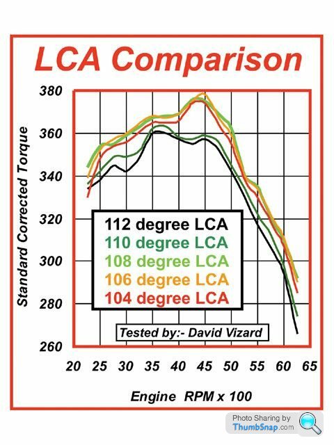
You could just as easily say the 106 degree curve is the optimum one. Usually a small change in LCA adds torque somewhere in the power band and takes it away somewhere else. It doesn't always give a nice clean best / worst situation with a clear winner.
So at the end of the day I can't agree that LCA is the most important factor in cam choice as DV says in various books and articles. Cam duration is far more important IMO and as long as you make sensible choices for LCA you can get right into the ballpark without undue testing.
If I had to pick a single LCA for an unknown engine I'd probably go with around 106 to 107 degrees. I used to use wider angles but I was probably over biased by the volume of literature on the Chevy engine. The famous Chevy tuner Bill Jenkins used to use 109 degrees in every engine he built, big, small, track or drag race. He stuck to it like it was some sort of magic number and I think I was too much influenced by this many years ago.
As DV states it's more important to not pick too wide an angle so even if the ideal was a couple of degrees more than 106/107 you wouldn't be losing much and there are not many engines that want much less than 106 so again you're unlikely to be far out.
Obviously some account has to be taken of CR and other factors but we don't all have the money and resources to test every possible cam so you have to make your best guess and live with it.
My personal opinion is that DV has become somewhat sucked into this issue trying to find a magic rule to quote to the extent that perhaps some objectivity has been lost. I'd like to see the vast amount of data he's no doubt accumulated and cast a fresh eye over it. I bet a pound to a penny I wouldn't fit the data to a chart in the same way or at least nothing as simple as a straight line.
Rwdfords said:
A 2.0 pinto with 44.45mm inlets would be 108* LSA going by the chart which is about optimum I think, and 110* LSA with 46mm inlets, also quite close to what is needed
Geometrically the 2 litre Pinto is almost identical to one half of a 350 Chevy and I'm not just talking about bore/stroke ratio here or indeed anything to do with valve sizes. I'm also not going to say exactly what I am talking about just yet.You can therefore bet with some certainty that it will want a similar LCA. IMO 110 would be far too wide for a long duration cam. I'd go with 107. That's very unlikely to be more than 1 degree out either way.
You need to stop thinking about valve size or CID/inch of valve diameter in relation to selecting an LCA. Trying to find such a relationship is a bit like going on a clitoris hunt. You might suspect one exists but your chances of finding it are very slim.
Interesting thread.. looking at the graph, can I assume that the curves are derived from a single camshaft which has the LCA moved around rather than a number of cams with the LCA and lobe separation tailored to suit. If that is the case, what was the lobe separation angle?, where is the notional 'nuetral' position of the cam WRT LCA?. The reason I ask is that moving the LCA on the inlet will have an affect on the exhaust LCA as well. It's one thing to determine the ideal LCA and cut a cam with correct LCA and lobe separation, but another altogether to simply swing an existing cam through an LCA arc as this will move both lobe centres. On twin cam engines there is scope for moving each cam independently to arrive at the optimum for each camshaft. On a single cam engine this needs to be determined before the cam is cut.
As an aside, on many 4 valve engines with long duration cams (275 degrees or above) a lobe centre of 102-104 on the inlet and 104-106 on the exhaust works very well.
Dave
As an aside, on many 4 valve engines with long duration cams (275 degrees or above) a lobe centre of 102-104 on the inlet and 104-106 on the exhaust works very well.
Dave
Edited by DVandrews on Wednesday 25th January 11:16
Quote from Dave Bakers post a few up the page:-
My personal opinion is that DV has become somewhat sucked into this issue trying to find a magic rule to quote to the extent that perhaps some objectivity has been lost. I'd like to see the vast amount of data he's no doubt accumulated and cast a fresh eye over it. I bet a pound to a penny I wouldn't fit the data to a chart in the same way or at least nothing as simple as a straight line.
Dave, as usual, you have put a lot of thought provoking stuff out there - most with great merit. You are right on the money with the comment that I am trying to find a simple rule of thumb for the LCA. The curve you used above is actually a straight line and is a simplified version of the the curve (it dips down toward the wide end) of the graph in my 'How to Build Horsepower' book.
Just so you know my Cammaster program uses flow not valve size so be aware that valve size is a simplification. Also there are two sub routines in Cam Master - one for 2 valve engines and one for 4 valve. They give different results.
Just to get it over with I checked the 1275 A Series LCA using that graph and Dave - (god I hate this) you are right. The LCA predicted is off the map somewhere out in the boonies. But (and there is always a 'but') in my defense the A Series book gives what is needed specifically and is based on many many (really many dyno tests. My point - I did at least put the right answer out there (so can I get some credit for that please boss? - no-one, not even the factory, spent the time AND MONEY to put it out there before I did!)
AS usual Dave there is no fast answer to the wealth of comments you have thrown out there for, not just me but us all to contemplate. I have answers that will be seen to fit and explain some of the apparent anomalies you raise. However there are some that we really need to get together on the phone and discuss.
I get the feeling that this is going to be a great thread here. already some obiously educated minds have responded. In need to sit down and address as many points as possible here to ticdy up some misconcetions. Howver I also see that Dave's comments are starting to uncover the LCA question at a much deeper level than is normally seen in any formum(Why am I not surprised!) Guys and Dave in particular lets talk on this there may be some new truths to uncover. Right now i have a proposal to do that is being a particular bear so will get back to this when thas done and out of the way.
Will talk to you soon DB
Thanks
DV
DVandrews said:
Interesting thread.. looking at the graph, can I assume that the curves are derived from a single camshaft which has the LCA moved around rather than a number of cams with the LCA and lobe separation tailored to suit. If that is the case, what was the lobe separation angle?, where is the notional 'nuetral' position of the cam WRT LCA?. The reason I ask is that moving the LCA on the inlet will have an affect on the exhaust LCA as well. It's one thing to determine the ideal LCA and cut a cam with correct LCA and lobe separation, but another altogether to simply swing an existing cam through an LCA arc as this will move both lobe centres. On twin cam engines there is scope for moving each cam independently to arrive at the optimum for each camshaft. On a single cam engine this needs to be determined before the cam is cut.
As an aside, on many 4 valve engines with long duration cams (275 degrees or above) a lobe centre of 102-104 on the inlet and 104-106 on the exhaust works very well.
Dave
DV and myself are using the term LCA to refer to what you are calling LSA i.e the angle between the inlet lobe peak position and the exhaust lobe peak position. The actual cam timing in terms of advance or retard is given by the inlet full lift position which you are referring to as the LCA.As an aside, on many 4 valve engines with long duration cams (275 degrees or above) a lobe centre of 102-104 on the inlet and 104-106 on the exhaust works very well.
Dave
Maybe both myself and DV should start using the term LSA to refer to what we have previously called LCA. If he will I will.
Pumaracing said:
DVandrews said:
Interesting thread.. looking at the graph, can I assume that the curves are derived from a single camshaft which has the LCA moved around rather than a number of cams with the LCA and lobe separation tailored to suit. If that is the case, what was the lobe separation angle?, where is the notional 'nuetral' position of the cam WRT LCA?. The reason I ask is that moving the LCA on the inlet will have an affect on the exhaust LCA as well. It's one thing to determine the ideal LCA and cut a cam with correct LCA and lobe separation, but another altogether to simply swing an existing cam through an LCA arc as this will move both lobe centres. On twin cam engines there is scope for moving each cam independently to arrive at the optimum for each camshaft. On a single cam engine this needs to be determined before the cam is cut.
As an aside, on many 4 valve engines with long duration cams (275 degrees or above) a lobe centre of 102-104 on the inlet and 104-106 on the exhaust works very well.
Dave
DV and myself are using the term LCA to refer to what you are calling LSA i.e the angle between the inlet lobe peak position and the exhaust lobe peak position. The actual cam timing in terms of advance or retard is given by the inlet full lift position which you are referring to as the LCA.As an aside, on many 4 valve engines with long duration cams (275 degrees or above) a lobe centre of 102-104 on the inlet and 104-106 on the exhaust works very well.
Dave
Maybe both myself and DV should start using the term LSA to refer to what we have previously called LCA. If he will I will.
Edited by v8 racing on Wednesday 25th January 19:43
Just some info for any learners looking at this thrtead in time to come,,
LSA lobe separation angles, the angle of degrees between the centre of the intake and exhaust lobe. A fixed angle on a single cam that contains both inlet and exhaust lobes.
LCA lobe centre angle. The centreline of a single lobe.
LSA lobe separation angles, the angle of degrees between the centre of the intake and exhaust lobe. A fixed angle on a single cam that contains both inlet and exhaust lobes.
LCA lobe centre angle. The centreline of a single lobe.
Workshop said:
Just some info for any learners looking at this thrtead in time to come,,
LSA lobe separation angles, the angle of degrees between the centre of the intake and exhaust lobe. A fixed angle on a single cam that contains both inlet and exhaust lobes.
LCA lobe centre angle. The centreline of a single lobe.
Hi workshop, i no what you are saying, but the lsa doesnt have to be a fixed single cam, you can have 1-2-3-4 or how many you want and still have a lsa, i am sure we both no what we mean but in different words.LSA lobe separation angles, the angle of degrees between the centre of the intake and exhaust lobe. A fixed angle on a single cam that contains both inlet and exhaust lobes.
LCA lobe centre angle. The centreline of a single lobe.
Ok, so I took the Honda 600 as an example. which worked out to:
Size of one cylinder in CI was 8.402 and intake valve sizes is 2.165 in total.
Then I looked at the RPM of the engine and decide to use CFM instead.
Total CFM for that displacement of one clyinder at 15000RPM at 100% VE is
39.5 CFM which I divided by the valve size of 2.16 which gave me 18.28 CFM
that was then added to the formula
LSA = 132 - (16/14 x 18.28)
So LSA ended up at approx 111
This got me closer but no cigar, unless there are some other deductions I can make to this total or my idea was just total b ks... anyway, It's all got me thinking so it's back to the drawing board..
PS I did find as VE goes up the LSA number came down 105 VE gave me 110 LSA.
Size of one cylinder in CI was 8.402 and intake valve sizes is 2.165 in total.
Then I looked at the RPM of the engine and decide to use CFM instead.
Total CFM for that displacement of one clyinder at 15000RPM at 100% VE is
39.5 CFM which I divided by the valve size of 2.16 which gave me 18.28 CFM
that was then added to the formula
LSA = 132 - (16/14 x 18.28)
So LSA ended up at approx 111
This got me closer but no cigar, unless there are some other deductions I can make to this total or my idea was just total b
ks... anyway, It's all got me thinking so it's back to the drawing board..PS I did find as VE goes up the LSA number came down 105 VE gave me 110 LSA.
Edited by Workshop on Wednesday 25th January 21:47
Edited by Workshop on Wednesday 25th January 21:57
Edited by Workshop on Wednesday 25th January 22:03
Workshop said:
Ok, so I took the Honda 600 as an example. which worked out to:
Size of one cylinder in CI was 8.402 and intake valve sizes is 2.165 in total.
Then I looked at the RPM of the engine and decide to use CFM instead.
Total CFM for that displacement of one clyinder at 15000RPM at 100% VE is
39.5 CFM which I divided by the valve size of 2.16 which gave me 18.28 CFM
that was then added to the formula
LSA = 132 - (16/14 x 18.28)
So LSA ended up at approx 111
This got me closer but no cigar, unless there are some other deductions I can make to this total or my idea was just total bks... anyway, It's all got me thinking so it's back to the drawing board..
PS I did find as VE goes up the LSA number came down 105 VE gave me 110 LSA.
No no no Cam Master does not use cfm like this:- Total CFM for that displacement of one clyinder at 15000RPM at 100% VE isSize of one cylinder in CI was 8.402 and intake valve sizes is 2.165 in total.
Then I looked at the RPM of the engine and decide to use CFM instead.
Total CFM for that displacement of one clyinder at 15000RPM at 100% VE is
39.5 CFM which I divided by the valve size of 2.16 which gave me 18.28 CFM
that was then added to the formula
LSA = 132 - (16/14 x 18.28)
So LSA ended up at approx 111
This got me closer but no cigar, unless there are some other deductions I can make to this total or my idea was just total b
ks... anyway, It's all got me thinking so it's back to the drawing board..PS I did find as VE goes up the LSA number came down 105 VE gave me 110 LSA.
Edited by Workshop on Wednesday 25th January 21:47
Edited by Workshop on Wednesday 25th January 21:57
Edited by Workshop on Wednesday 25th January 22:03
39.5 CFM which I divided by the valve size of 2.16 which gave me 18.28 CFM
that was then added to the formula
LSA = 132 - (16/14 x 18.28)
The result you have here is totally fortuitous. (Nice try though!!)
DV
Thanks David, it was really just a stab in the dark while I was having a coffee before I went to work. Really there was no sense trying to adapt CFM to the formula because I have no idea why it is multiplied by 16/14 and then 132 subtracted by it in the first place. 
I just had a strange idea that the amount of air that is put through the cylinder may have had an effect on it since that engine sees 15000 RPM with such a large valve size for that cylinder displacement..
My thinking cap is still on
I just had a strange idea that the amount of air that is put through the cylinder may have had an effect on it since that engine sees 15000 RPM with such a large valve size for that cylinder displacement..
My thinking cap is still on
Edited by Workshop on Thursday 26th January 04:59
Gassing Station | Engines & Drivetrain | Top of Page | What's New | My Stuff