flow bench program
Discussion


Using the calculation in 10.2.2 the uncertainty is ±1.2% (*), so...
there is a 95% probability that
217.2cfm < actual volumetric flow rate at test orifice < 222.5cfm
(*) The uncertainty would be worse than this as BS1042 assumes that the air density, viscosity and isentropic component are for the pressure and temperature at the upstream tapping plane, not ambient.
Air density calculator
Air dynamic viscosity calculator
Air isentropic exponent calculator (can be used to estimate isentropic exponent to 4 significant places)
Edited by pingu393 on Friday 19th October 23:17
My flow bench went through many variants until I was happy with consistent results. I ended up with an orifice in a large space to another large space, being + 4 x d of orifice upstream, down stream and in a vertical plane to the orifice. This gave me very good consistency. I experimented with extra pressure readings all over the bench as well as temp readings. They made a minute difference to the figures, but, the figures with or without the extra tappings and temp sampling remained very close so I ended up with basic ambient temp sampled at each lift test and relative humidity sampled at each lift.
Not wanting to tell you how to be as the path to discovery of building and running your own flow bench is a good and satisfying path to tread, but, I assume the end aim is to test items which may be subject to improvement or detriment of flow depending on what mods are tried. as long as you get consistent, repeatable results and an improvement is an improvement and a loss is a loss when tested in terms of actual flow then you have a good, reliable and useful tool to hand in the quest for power.
Not wanting to tell you how to be as the path to discovery of building and running your own flow bench is a good and satisfying path to tread, but, I assume the end aim is to test items which may be subject to improvement or detriment of flow depending on what mods are tried. as long as you get consistent, repeatable results and an improvement is an improvement and a loss is a loss when tested in terms of actual flow then you have a good, reliable and useful tool to hand in the quest for power.
PeterBurgess said:
My flow bench went through many variants until I was happy with consistent results......a good, reliable and useful tool to hand in the quest for power.
Humbug. You trot this nonsense out every time flow measurement comes up in here. No matter what you get wrong with pressure tappings, orifice design or placement a flow bench will be consistent. Just consistently wrong like yours is. The manometer readings don't vary randomly just because some part of the design is faulty. You never did a damn thing to obtain more consistency as that was already there so please stop the pretence but you did mess about to try and make it read closer to what accurate professional flowbenches read as yours reads far too low and you know it.I told you exactly what was wrong with your bench 30 years ago Peter after Dave Vizard helped me get the design of my own one right but you took no notice because you didn't want to throw away all your existing flow tests as being inaccurate and start from scratch like any good scientist would have done. Instead you peddle this "it might not be accurate but it's consistent" BS to try and cover your own sloppiness. That's when I lost all respect for your scientific integrity Peter, not because you made some mistakes, but because you refused to correct them when told about them.
Now you defend Pingu's using 0.5956 as an orifice coefficient instead of working it out properly because in reality you want to try and defend your own similar mistakes and claim that accuracy doesn't matter as long as it's just for your own use. Well accuracy does matter when it's a measuring device. In fact it's the whole bloody point of such a thing. I remember you saying you didn't believe Dave Vizard's flow figures because you could never get anywhere close to them on Pintos. You couldn't compare you Mini heads to Glynn Swift's or Dave Walker's. After I got my bench right I told you why. Your bench reads wrong. Simples.
A bench designed to BS 1042 with an orifice plate in a long tube works perfectly just like the standard says it will. In fact the long tube is necessary to let the flow stabilise before it reaches the orifice. The standard recommends at least 20D of tube length before the orifice plate and I experimented with 10D and 20D and found the latter is indeed beneficial.
To Pingu now. There are some things you absolutely need to get right in any flowbench design. The manometer tappings must be in accordance with the standard. The one measuring the pressure drop across the test piece must be right at the top of the tube the test piece sits on and not anywhere down lower like Peter's. Pressure recovery takes place as you get further from any restriction and you get a different pressure drop than is correct. This creates a non linear error in the bench readings you can never correct for. The higher the flow rate the greater the pressure recovery and the greater the error. This always creates an over-reading condition where the measured pressure drop across the test piece is too low and the calculated flow figures are too high. At low valve lifts, low flow rate the percentage error is smaller than at high valve lift, high flow rates. This also means that as you modify a head you fool yourself into thinking you've achieved a bigger percentage improvement than has actually happened.
Same applies to the orifice plate. Both tappings must be close to it. I went with 1 inch either side. The orifice plate must either be correctly made to the specs in the standard if you want to calculate its cD or alternatively you can use any old hole punched in a sheet of metal or wood and calibrate your discharge coefficient to someone else's proper bench later. Venturi tubes or nozzles work fine. In fact any shaped hole works fine as long as you can either calculate or calibrate its cD. You can only calculate though if it's made to the specs in the standard. You can get away with an orifice in a wide short drum but then you do need to calibrate it to a proper bench later. I opted to do everything exactly to BS 1042 though and never regretted it. Short cuts in life end up biting you in the backside.
Mignon said:
Short cuts in life end up biting you in the backside.
I'm on my third redesign, so I can vouch for that 
My first one was very compact and was perfectly ok for the comparative work that I was doing. I basically hooked a vacuum cleaner up to a box with a control valve, set the manometer to a mark and tested different parts. If a part showed a lower depression than another, it meant it flowed more - simple as that.
Then people started asking "what's the flow rate?" That's why I'm trying to make something better. By the time I'm finished, it would have probably been cheaper to buy a SuperFlow - but where's the fun in that

BTW, I only used the figures that were in the program. None of the figures were mine. Not that it matters, as the object of the exercise was to test the modification to the program. Now that I've done a long-hand calculation, I will modify the program to do the BS1042 calculations, but don't expect anything this side of Christmas.
pingu393 said:
I've used the online calculator was wondering why the vapour pressure default was 3 N/m². Using http://www.endmemo.com/chem/vaporpressurewater.php, the value should be 1697 N/m².
Hoping that I have used the vapour pressure correctly, I have modified the flowbench calculator so the vapour pressure is calculated inside the script...
http://www.porterbility.co.uk/flowbench_calculator...
Please let me know if I've done anything wrong.
Do not know why I used a default value of 3, but the original script was programmed with that being an input field / supplied by the user.Hoping that I have used the vapour pressure correctly, I have modified the flowbench calculator so the vapour pressure is calculated inside the script...
http://www.porterbility.co.uk/flowbench_calculator...
Please let me know if I've done anything wrong.
Stan
Dave
I am very happy with my flow bench. You first came to see me to learn about the work I do and how I built my bench in 1988 and I made you very welcome, you built your own afterwards and that is great. You stayed with me at my house frequently from 1988 to about 1992 and we worked together and learned a lot, it was a very intense time for learning.
You gave me support when Mary left me for which I am grateful. So, despite some folk thinking you are nasty and do not tolerate others at times I know you have a gentler side too. i see that sometimes in your postings.
No need to keep rubbishing my bench, as I said it has worked since 1985 and the flow development has helped me to win championships from 1987 to 2018 with no gaps. At that I would say the bench does the job I wanted it to.The bench and all the maths was used for a degree thesis and it passed except for one panel member querying the 0.596 CD. The books that I have written with Dave Gollan are used in Motorsport higher education qualifications up to degree level.
I learned a lot about the financial side of running a business from you for which I am ever grateful, it has helped me keep the business running for 32 years or so and seen it through many recessions. The best thing you taught me was to run the business for monetary requirements to break even over a 48 week period not a 52 week to allow for holidays etc etc, I have never seen this info anywhere else and I try and tell people setting up in business who seek my advice ( not necessarily car tuning) about someone who was my friend who gave excellent advice about successful budgeting. Working with me and learning from me and building a flow bench which you feel is better than mine is good and it means I have passed on and shared knowledge which I do with a lot of folk, as I enjoy helping people..
I've just written a CFM Calculator in Excel...
http://www.porterbility.co.uk/Files/XLS/Flow_Bench...
I've hidden most of the sheets, but feel free to check the maths. (Unprotect the workbook and unprotect the protected sheets as appropriate.)
You only need to populate the yellow fields, the red fields show the nominal values that are used later in the calculator. The Roman numerals beside the orifice data are the axes where the measurements were made...
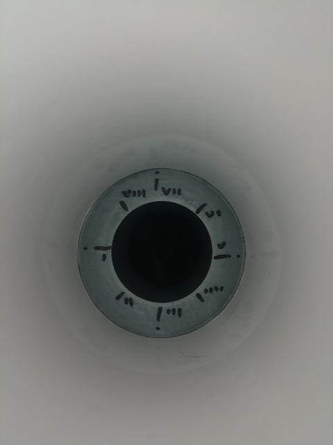
The orifice above as made using my 3D printer and the measurements for it are correct. All the other data values are guestimates that I used to prove the program.
This calculator uses the calculations for C given in BS1042 Part 1 Section 1 : 1981 (Stolz). The calculation for C given in ASME MFC-3M-2004 and ISO5167-2:2003 is different. They use the Reader-Harris/Gallagher (1998) equation. I hope to do another calculator for that later.
I have observed that making a flow bench that will satisfy the standards' requirements is not practical for this home engineer (the tolerances are just too tight, and the rig would be too big). I like to think my results will be on the same ball park, just not in the centre circle
As I am outside the tolerances for the standards, I used my method of error estimation (uncertainty). The standards use standard deviation to calculate uncertainty. I use worst case scenario. My method gives a much wider range, but I feel this is appropriate.
Your thoughts?
http://www.porterbility.co.uk/Files/XLS/Flow_Bench...
I've hidden most of the sheets, but feel free to check the maths. (Unprotect the workbook and unprotect the protected sheets as appropriate.)
You only need to populate the yellow fields, the red fields show the nominal values that are used later in the calculator. The Roman numerals beside the orifice data are the axes where the measurements were made...
The orifice above as made using my 3D printer and the measurements for it are correct. All the other data values are guestimates that I used to prove the program.
This calculator uses the calculations for C given in BS1042 Part 1 Section 1 : 1981 (Stolz). The calculation for C given in ASME MFC-3M-2004 and ISO5167-2:2003 is different. They use the Reader-Harris/Gallagher (1998) equation. I hope to do another calculator for that later.
I have observed that making a flow bench that will satisfy the standards' requirements is not practical for this home engineer (the tolerances are just too tight, and the rig would be too big). I like to think my results will be on the same ball park, just not in the centre circle
As I am outside the tolerances for the standards, I used my method of error estimation (uncertainty). The standards use standard deviation to calculate uncertainty. I use worst case scenario. My method gives a much wider range, but I feel this is appropriate.
Your thoughts?
You have worked really hard on your project. Once it has all settled in and you are getting repeatable figures you can get down to the nitty gritty of learning what effects changes in ports etc make on airflow and see what improvements can be made and then see if the improvements always improves bhp, throttle response, fuel economy etc etc Enjoy.
Mignon said:
I don't exactly agree your calculations. Maybe the easiest thing is if I send you my own BS1042 calculation spreadsheet and you can work through it. Give me an email address.
Your preferences are set to not accept e-mails. I think that you can e-mail me. If not, I'll change my preferences so that you can.Gary
Mignon said:
http://www.porterbility.co.uk/Files/XLS/Flow_Bench... My spreadsheet. The only guess is the downstream v. ambient delta.http://www.porterbility.co.uk/Files/XLS/Bench1_Ame... (I have slightly amended the workbook. You need manual intervention to update Re for each iteration)
I've had a good look through your program. I think that the differences are down to subtly different choices of values and using different methods to achieve the same result.
1. I have introduced more factors,
a) thermal expansion
b) different temperature at the upstream tap
The latest version of my spreadsheet (not published yet) includes factoring elevation to adjust the value of P(amb).
2. You have assumed that P1 is P(amb) + Delta P(test)
I have assumed that P1 is P2 - Delta P(orifice)
In the future, I will be measuring absolute P1 and absolute P2, and correcting them for elevation. (I use electronic manometers rather than water-filled ones)
3. You use a value for air density calculated from the density of water and acceleration under gravity.
I use a value from the internet.
4. You calculate Kinematic Viscosity (value = 1.48E-5)
I use a value from the internet for Dynamic Viscosity (value = 1.91E-5)
5. You use Re = (Mean Axial Velocity x Upstream Pipe Diameter) / (Kinematic Viscosity) [see 2.4.2 of BS1042-1.1(1981)]
I use Re = (4 x Mass Flow Rate) / (PI x Upstream Pipe Diameter x Dynamic Viscosity) [see 7.3(l) of BS1042-1.4(1992)]
There are many opportunities to introduce error in a homemade flow bench. For us to be within 3% of each other (220 v 214) is quite a miracle
pingu393 said:
3. You use a value for air density calculated from the density of water and acceleration under gravity.
I use a value from the internet.
Well it's calculated from actual temp and air pressure but yes, you can't just take an internet number and not adjust it for those factors. It's one of the most important parts of the calculation.I use a value from the internet.
pingu393 said:
4. You calculate Kinematic Viscosity (value = 1.48E-5)
I use a value from the internet for Dynamic Viscosity (value = 1.91E-5)
Again, ditto.I use a value from the internet for Dynamic Viscosity (value = 1.91E-5)
I'm puzzled about your complexity of calculation in some areas like thermal expansion but then ignoring other fundamental parts of the calculation.
Mignon said:
pingu393 said:
3. You use a value for air density calculated from the density of water and acceleration under gravity.
I use a value from the internet.
Well it's calculated from actual temp and air pressure but yes, you can't just take an internet number and not adjust it for those factors. It's one of the most important parts of the calculation.I use a value from the internet.
pingu393 said:
4. You calculate Kinematic Viscosity (value = 1.48E-5)
I use a value from the internet for Dynamic Viscosity (value = 1.91E-5)
Again, ditto.I use a value from the internet for Dynamic Viscosity (value = 1.91E-5)
I'm puzzled about your complexity of calculation in some areas like thermal expansion but then ignoring other fundamental parts of the calculation.
http://www.porterbility.co.uk/Files/PDF/BS_1042_1_... (p.14 of the pdf, p.10 of the document)
Their example is for a steam pipe, so the thermal expansion was relevant. I doubted that it would be necessary at near-ambient conditions, but there is a 0.1% difference in a U-PVC pipe at 7°C deltaT, so I kept it in.
I'm not aware of having ignored any part of the calculation. The values from the internet that I use are calculated from actual temperature and pressure. I'm waiting for a hygrometer, so I have estimated humidity at 50%.
Using your figures in my latest evolution of the ISO5167 spreadsheet (not yet published), q(v) @ 25" = 225.7 cfm. My assumptions were Delta P2 / P(Ambient) = 50mm H2O & humidity = 50%.
Something to note...
Air Density @ 15°C / 1013.25 / 4.7°C dew point = 1.2216 kg/cu m --- (1)
Air Density @ 15°C / 1042.7 (P1) / 4.7°C = 1.2567 kg/cu m --- (2)
Air Density @ 23°C (T1*) / 1042.7 / 12°C = 1.2203 kg/cu m --- (3)
You don't seem to make allowance for any changes in air density as the air is heated and pressurised. Comparing 1 to 3, I can see why.
My spreadsheet does take account of the changes, but as T1 = T(amb) in your assumptions, the result using my spreadsheet will be wrong.
(T1*) was measured on my rig at 5D downstream from the orifice. This is a fair approximation of the actual T1 without disrupting the air flow.
My spreadsheet is based on calculations needed for D-D/2 arrangement. You are using a Flange arrangement. Without re-reading the standard, I don't know what difference this will make to the calculations, if any.
pingu393 said:
You don't seem to make allowance for any changes in air density as the air is heated and pressurised.
My bench has the vacuum source downstream of the measuring orifice so no heating of the air takes place inside the bench. I calculate the air density correctly for pressure drops and ambient temperature.Mignon said:
pingu393 said:
You don't seem to make allowance for any changes in air density as the air is heated and pressurised.
My bench has the vacuum source downstream of the measuring orifice so no heating of the air takes place inside the bench. I calculate the air density correctly for pressure drops and ambient temperature.Gassing Station | Engines & Drivetrain | Top of Page | What's New | My Stuff