Injector Swap 2008 325i se - Am I being ripped off?
Discussion


Injectors fail on these and if one is going then it places increased work on the other injectors, so one going means others will follow, which is why I replaced all 6 in one go on my 335i when one failed. Personally, I would go done the route of getting all done. If willing to do it yourself, then maybe try sourcing the parts from somewhere like Autodoc (about £130 each at the moment).
Update. Nest removed. It seems whatever decided to live there also took a bite at some cables. The cables inside seem fine but hard to tell.
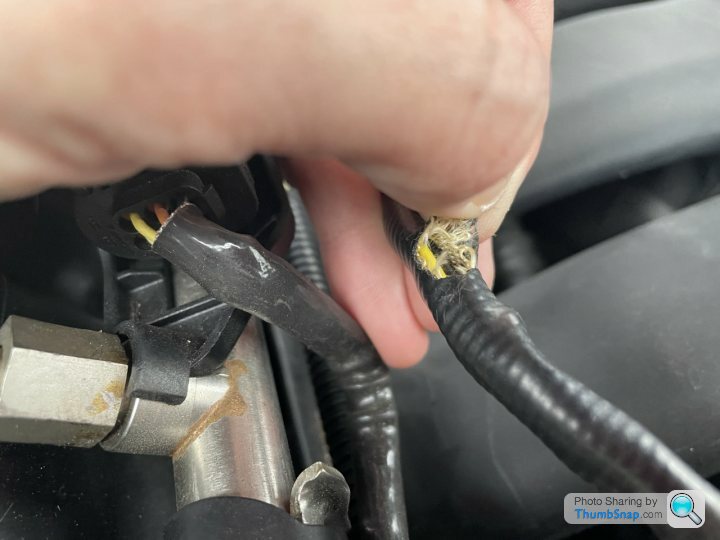
Maybe it took a bite elsewhere as well?

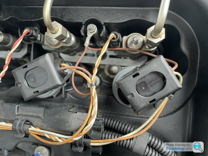
Right, prepping for the pack swap on 1&2 next, unless anyone know of a way to diagnose the cables / outputs?
Maybe it took a bite elsewhere as well?
Right, prepping for the pack swap on 1&2 next, unless anyone know of a way to diagnose the cables / outputs?
Hard to tell what those trunks/conduits are, but one looks like going to front of engine (vanos etc?) and the other looks like oxygen sensor. I'd be inspecting those very carefully or ideally checking continuity at the DME (ECU) end back to the coilpack and injector connectors.
The error code suggested open circuit on the injector did it not, not coilpack, so i'm not sure why you are swapping coilpacks? The voltage at the injector is 250v DC iirc so take care there. Open circuit sounds like continuity to me, or failed MOSFET, as the injectors don't tend to die they tend to leak and poor spray pattern etc.
GL
Right, did some measurements (connected voltimeter - one pin from the injector power plug and one to the positive on the battery and I am getting around 11V on both injector one and two.
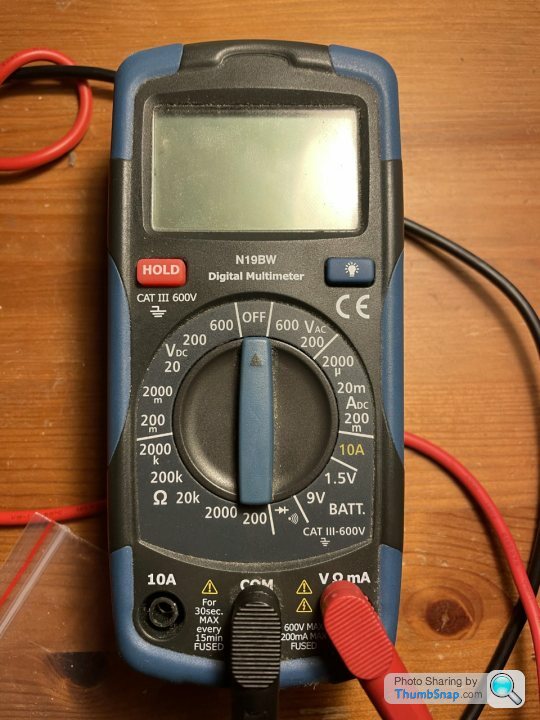
Now I would like to measure the actual output on that plug, someone has mentioned 250V DC, can you confirm which mode should I put the voltimeter to? 200ma or 10A? Don't want to blow the thing!
Thanks in advance.
Now I would like to measure the actual output on that plug, someone has mentioned 250V DC, can you confirm which mode should I put the voltimeter to? 200ma or 10A? Don't want to blow the thing!
Thanks in advance.

I just wanted to check where your leads were plugged in 
I can’t advise on swapping injectors around, as I don’t have the technical knowledge of the effect. Ditto, I’ve not worked on BMW’s before.
However, for wiring testing, it’s very rare I use the positive of the car for any testing.
You really want your black lead connected to the negative of the car, for most testing.
From there on in, for checking voltages to your injectors, set your meter to 20VDC, and touch your red probe against the pins of the connector. Be careful not to push your probe up the pins, you don’t want them pins opening up, as they won’t make a connection with the pins in the injector.
If you ever want to check for open pins, get a needle set, start with the thinnest needle and gently push it into the connector. The connector should grab it. It helps if you have more than one pin of the same type, as you can compare the ‘feel’ from one pin to another. Some connectors naturally have quite wide pins, especially if they’re carrying a big load, and sometimes even the thickest needle isn’t wide enough for testing them.
The 250vdc figure quoted above, surprised me. But keep your meter on the 20VDC setting. If the voltage you’re measuring is higher than 20V, you’ll get an ‘OL’ (out of limits) warning on your meter. In which case, set your meter to the next highest reading, 200VDC on your meter. Repeat test, if it’s another ‘OL’, then set your meter to 600VDC.
55V is the highest I’ve seen on a car, and that’s on the MHEV side.
If you’re looking for negatives... Keep your black probe on the negative of the car. Set your meter to 200ohms... due south on your meter... then touch your red probe against the pin of the connector. A hard ground (where the wire your testing is connected to the body) will typically read below 50ohms. I presume your injectors are fed by the engine ecu ? If so, I find ‘electronic grounds’ that come from a module, will typically read between 50 ohms and 100 ohms. Same again, if you get an ‘OL’, go for the next setting up, so 2000 ohms on your meter. And so on and so on.
Sometimes I may not be looking for a a positive voltage or a negative, but I may just want to see if there’s anything connected to the end of a wire. Unless you’re reading across the normally open contact of a relay, in general, you’ll get a bit of resistance when probing most wires.
You’ve obviously got three scenarios when testing.... Ignition off, ignition on, engine running.
Hopefully some of that helps you along your way.
I can’t advise on swapping injectors around, as I don’t have the technical knowledge of the effect. Ditto, I’ve not worked on BMW’s before.
However, for wiring testing, it’s very rare I use the positive of the car for any testing.
You really want your black lead connected to the negative of the car, for most testing.
From there on in, for checking voltages to your injectors, set your meter to 20VDC, and touch your red probe against the pins of the connector. Be careful not to push your probe up the pins, you don’t want them pins opening up, as they won’t make a connection with the pins in the injector.
If you ever want to check for open pins, get a needle set, start with the thinnest needle and gently push it into the connector. The connector should grab it. It helps if you have more than one pin of the same type, as you can compare the ‘feel’ from one pin to another. Some connectors naturally have quite wide pins, especially if they’re carrying a big load, and sometimes even the thickest needle isn’t wide enough for testing them.
The 250vdc figure quoted above, surprised me. But keep your meter on the 20VDC setting. If the voltage you’re measuring is higher than 20V, you’ll get an ‘OL’ (out of limits) warning on your meter. In which case, set your meter to the next highest reading, 200VDC on your meter. Repeat test, if it’s another ‘OL’, then set your meter to 600VDC.
55V is the highest I’ve seen on a car, and that’s on the MHEV side.
If you’re looking for negatives... Keep your black probe on the negative of the car. Set your meter to 200ohms... due south on your meter
... then touch your red probe against the pin of the connector. A hard ground (where the wire your testing is connected to the body) will typically read below 50ohms. I presume your injectors are fed by the engine ecu ? If so, I find ‘electronic grounds’ that come from a module, will typically read between 50 ohms and 100 ohms. Same again, if you get an ‘OL’, go for the next setting up, so 2000 ohms on your meter. And so on and so on.Sometimes I may not be looking for a a positive voltage or a negative, but I may just want to see if there’s anything connected to the end of a wire. Unless you’re reading across the normally open contact of a relay, in general, you’ll get a bit of resistance when probing most wires.
You’ve obviously got three scenarios when testing.... Ignition off, ignition on, engine running.
Hopefully some of that helps you along your way.
Edited by RUSSELLM on Friday 26th March 01:30

Not sure if anyone's following this still, I will re-post and re-focus on my next issue if so...
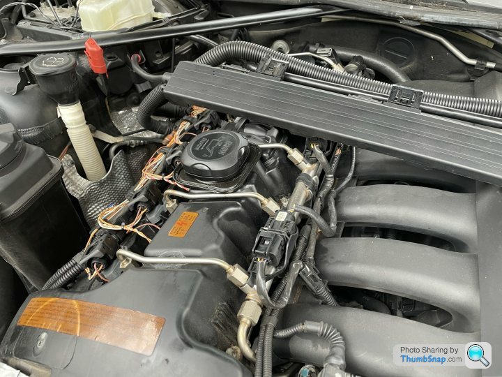
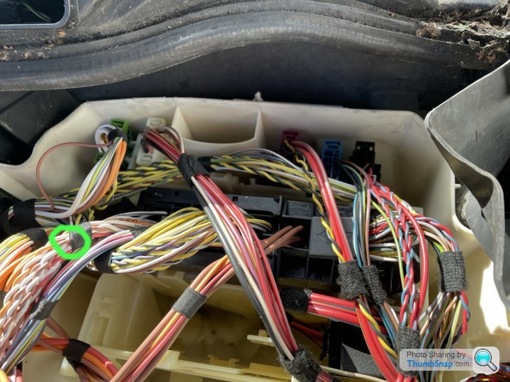
I need to perform some MOSFET tests (I do know how to btw) I just need some pointers on how to get to this box / get it out.
From top left - Do I disconnect the White, Pink, Blue and Black connectors to make it easier to access it?
Can I do that? Or will it cause issues later on?
I assume the black bit in the middle is some sort of bracket-connector and can be detached from the metal control box?
I have traced all injector power supply cables back into this box, so this has to be the place?
Need to check continuity on all of those injector power leads (green circle) and if all is good - proceed with the MOSFET testing bit.
I would appreciate your input guys, I made it this far, I really don't want to quit yet..
Gassing Station | BMW General | Top of Page | What's New | My Stuff